

 Manufacturers
M-SYSTEMS W2VF
Description
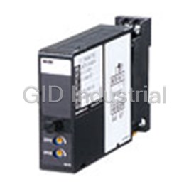
M-Systems W2VF Mini-MW Series Space-saving Dual Output Signal Conditioner; Signal Transmitter (High Speed Response)
Part Number
W2VF
Price
Request Quote
Manufacturer
M-SYSTEMS
Lead Time
Request Quote
Category
TBD
Specifications
AC Power input
Approx. 4 VA at 100 V; Approx. 5 VA at 200 V; Approx. 6 VA at 240 V
Accuracy
±0.1 %
Connection
M3 screw terminals (torque 0.8 N•m)
Construction
Plug-in
DC Power input
Approx. 3 W
Dielectric strength
2000 V AC @1 minute (input or output1 or output 2 to power to ground); 1000 V AC @1 minute (input to output 1 to output 2)
Housing material
Flame-resistant resin (black)
Insulation resistance
Greater than 100 MO with 500 V DC
Isolation
Input to output 1 to output 2 to power
Line voltage effect
±0.1 % over voltage range
Mounting
Surface or DIN rail
Operating humidity
30 to 90 %RH (non-condensing)
Operating temperature
-5 to +55°C (23 to 131°F)
Over-range output
Approx. -10 to +120 % at 1 – 5 V
Response time
= 180 µsec. (0 – 90 %)
Span adjustment
95 to 105 % (front)
Temp. coefficient
±0.015 %/°C (±0.008 %/°F)
Weight
Approx. 200 g (0.44 lbs)
Zero adjustment
-5 to +5 % (front)
Features
- 180-microsecond response
- 2000V AC isolation
- Base socket included with modules
- CE marking and UL/C-UL Class 1 Div 2 approval
- Converts DC input from a sensor into two standard process signals
- Fixed range or PC programmable models selectable
- Isolation between input and output
- Selectable 100-240V AC/24V DC power input
- Standard DIN rail or surface mounting
- Two independent output ranges
- W2 use a compact-size, plug-in socket base for quick installation or replacement of modules without disturbing wiring.
Datasheet

Extracted Text
Model ZERO SPAN ZERO SPAN MODEL: W2VF FW: -10 – +10 mA DC (Input resistance 100 Ω) Space-saving Dual Output Signal Conditioners Z: Specify current (See INPUT SPECIFICATIONS) Mini-MW Series Voltage 3: 0 – 1 V DC (Input resistance 1 MΩ min.) SIGNAL TRANSMITTER 4: 0 – 10 V DC (Input resistance 1 MΩ min.) (high speed response) 5: 0 – 5 V DC (Input resistance 1 MΩ min.) 6: 1 – 5 V DC (Input resistance 1 MΩ min.) Functions & Features 4W: -10 – +10 V DC (Input resistance 1 MΩ min.) • Converts DC input from a sensor into two standard 5W: -5 – +5 V DC (Input resistance 1 MΩ min.) process signals 0: Specify voltage (See INPUT SPECIFICATIONS) • Isolation between input and output (Select ‘/N’ for ‘Standards & Approvals’ code.) • Two independent output ranges 01: Specify voltage (See INPUT SPECIFICATIONS) • 180-microsecond response (Select ‘/CE’ or ‘/UL’ for ‘Standards & Approvals’ code.) • CE marking • UL approval [2] OUTPUT 1 Current Typical Applications A: 4 – 20 mA DC (Load resistance 750 Ω max.) • Isolation for a vibration analyzing system B: 2 – 10 mA DC (Load resistance 1500 Ω max.) C: 1 – 5 mA DC (Load resistance 3000 Ω max.) 29.5 (1.16) D: 0 – 20 mA DC (Load resistance 750 Ω max.) E: 0 – 16 mA DC (Load resistance 900 Ω max.) F: 0 – 10 mA DC (Load resistance 1500 Ω max.) 89 G: 0 – 1 mA DC (Load resistance 15 kΩ max.) (3.51) GW: -1 – +1 mA DC (Load resistance 7000 Ω max.) FW: -10 – +10 mA DC (Load resistance 700 Ω max.) Z: Specify current (See OUTPUT SPECIFICATIONS) 124 (4.88) Voltage mm (inch) 1: 0 – 10 mV DC (Load resistance 10 kΩ min.) 2: 0 – 100 mV DC (Load resistance 100 kΩ min.) 3: 0 – 1 V DC (Load resistance 1000 Ω min.) MODEL: W2VF–[1][2][3]-[4][5] 4: 0 – 10 V DC (Load resistance 10 kΩ min.) 5: 0 – 5 V DC (Load resistance 5000 Ω min.) ORDERING INFORMATION 6: 1 – 5 V DC (Load resistance 5000 Ω min.) • Code number: W2VF-[1][2][3]-[4][5] 4W: -10 – +10 V DC (Load resistance 10 kΩ min.) Specify a code from below for each [1] through [5]. 5W: -5 – +5 V DC (Load resistance 5000 Ω min.) (e.g. W2VF-6A6-M2/CE) 0: Specify voltage (See OUTPUT SPECIFICATIONS) • Special input and output ranges (For codes Z & 0) Note: If one of the outputs should be a current range, [3] OUTPUT 2 specify it for the Output 1 to allow a greater load. Y: None Current [1] INPUT A: 4 – 20 mA DC (Load resistance 350 Ω max.) Current B: 2 – 10 mA DC (Load resistance 700 Ω max.) A: 4 – 20 mA DC (Input resistance 250 Ω) C: 1 – 5 mA DC (Load resistance 1400 Ω max.) B: 2 – 10 mA DC (Input resistance 500 Ω) D: 0 – 20 mA DC (Load resistance 350 Ω max.) C: 1 – 5 mA DC (Input resistance 1000 Ω) E: 0 – 16 mA DC(Load resistance 430 Ω max.) D: 0 – 20 mA DC (Input resistance 50 Ω) F: 0 – 10 mA DC (Load resistance 700 Ω max.) E: 0 – 16 mA DC (Input resistance 62.5 Ω) G: 0 – 1 mA DC (Load resistance 7000 Ω max.) F: 0 – 10 mA DC (Input resistance 100 Ω) GW: -1 – +1 mA DC (Load resistance 7000 Ω max.) G: 0 – 1 mA DC (Input resistance 1000 Ω) FW: -10 – +10 mA DC (Load resistance 700 Ω max.) H: 10 – 50 mA DC (Input resistance 100 Ω) Z: Specify current (See OUTPUT SPECIFICATIONS) GW: -1 – +1 mA DC (Input resistance 1000 Ω) Voltage http://www.m-system.co.jp/ W2VF SPECIFICATIONS ES-5514 Rev.7 Page 1/4 MODEL: W2VF Same range availability as Output 1 7 V max. for Output 2 (7 V for both outputs for bidirectional outputs) • DC Voltage: -10 – +12 V DC (up to 10 V for Output 2) [4] POWER INPUT Minimum span: 5 mV AC Power Offset: Max. 1.5 times span M: 85 – 264 V AC (Operational voltage range 85 – 264 V, Load resistance: Output drive 1 mA max.; at ≥ 0.5 V 47 – 66 Hz) (Select ‘/N’ for ‘Standards & Approvals’ code.) M2: 100 – 240 V AC (Operational voltage range 85 – 264 V, INSTALLATION 47 – 66 Hz) Power Consumption (90 – 264 V for UL) •AC Power input: DC Power Approx. 4 VA at 100 V R: 24 V DC Approx. 5 VA at 200 V (Operational voltage range 24 V ±10 %, ripple 10 %p-p max.) Approx. 6 VA at 240 V R2: 11 – 27 V DC •DC Power input: Approx. 3 W (Operational voltage range 11 – 27 V, ripple 10 %p-p max.) Operating temperature: -5 to +55°C (23 to 131°F) (Select ‘/N’ for ‘Standards & Approvals’ code.) Operating humidity: 30 to 90 %RH (non-condensing) P: 110 V DC Mounting: Surface or DIN rail (Operational voltage range 85 – 150 V, ripple 10 %p-p max.) Weight: Approx. 200 g (0.44 lbs) (Select ‘/N’ for ‘Standards & Approvals’ code.) PERFORMANCE in percentage of span [5] OPTIONS Accuracy: ±0.1 % STANDARDS & APPROVALS (must be specified) Temp. coefficient: ±0.015 %/°C (±0.008 %/°F) /N: Without CE or UL Response time: ≤ 180 μsec. (0 – 90 %) /CE: CE marking Line voltage effect: ±0.1 % over voltage range /UL: UL approval (CE marking) Insulation resistance: ≥ 100 MΩ with 500 V DC Dielectric strength: 2000 V AC @1 minute (input or output1 or output 2 to power to ground) GENERAL SPECIFICATIONS 1000 V AC @1 minute (input to output 1 to output 2) Construction: Plug-in Connection: M3 screw terminals (torque 0.8 N·m) Housing material: Flame-resistant resin (black) STANDARDS & APPROVALS Isolation: Input to output 1 to output 2 to power CE conformity: Overrange output: Approx. -10 to +120 % at 1 – 5 V EMC Directive (2004/108/EC) Zero adjustment: -5 to +5 % (front) EN 61000-6-4 (EMI) Span adjustment: 95 to 105 % (front) EN 61000-6-2 (EMS) Low Voltage Directive (2006/95/EC) EN 61010-1 INPUT SPECIFICATIONS Installation Category II • DC Current: Pollution Degree 2 Shunt resistor attached to the input terminals (0.5 W) Max. operating voltage 300 V Specify input resistance value for Z code. Input or output 1 or output 2 to power: Reinforced • DC Voltage: -300 – +300 V DC insulation (-30 – +30 V for the input code 01. Span 30 V max.) Input to output 1 to output 2: Functional insulation Minimum span: 1 V Approval: Offset: Max. 1.5 times span UL/C-UL nonincendive Class I, Division 2, Input resistance: ≥ 1 MΩ Groups A, B, C, and D hazardous locations (UL 1604, CAN/CSA-C22.2 No.213) OUTPUT SPECIFICATIONS UL/C-UL general safety requirements • DC Current: -10 – +20 mA DC (UL 61010B-1, CAN/CSA-C22.2 No.1010-1) Minimum span: 1 mA Offset: Max. 1.5 times span Load resistance: Output drive 15 V max. for Output 1; http://www.m-system.co.jp/ W2VF SPECIFICATIONS ES-5514 Rev.7 Page 2/4 MODEL: W2VF DIMENSIONS unit: mm (inch) 6 (.23) DIN RAIL 3 2 1 35mm wide 6 5 4 2–4.2x5 (.17x.20) MTG HOLE 6 (.24) deep 9 8 7 11–M3 SCREW 11 10 22 (.87) 29.5 (1.16) 23 (.91) 10 (.39) 84 (3.31) 114 (4.49) [4 (.16)] • When mounting, no extra space is needed between units. TERMINAL ASSIGNMENTS unit: mm (inch) INPUT RESISTOR (model: REM2) 3 2 1 6 5 4 9 8 7 11 10 Input shunt resistor attached for current input. SCHEMATIC CIRCUITRY & CONNECTION DIAGRAM Z S Isolation Low Drift Output + 1 7 + * Amplifier Driver SIGNAL SOURCE R OUTPUT 1 – 2 8 – Z S 4 Output + 3 Driver 5 OUTPUT 2 – 6 9 10 U(+) POWER 11 V(–) Base Socket *Input shunt resistor attached for current input. Remark: The section enclosed by broken line is only with 2nd output option. The W2VF, by its fast-response feature, is not designed to eliminate noise present in the input signal. Use a shielded twisted-pair cable for preventing noise entering through the input wiring. http://www.m-system.co.jp/ W2VF SPECIFICATIONS ES-5514 Rev.7 Page 3/4 89 (3.50) 53 (2.09) 19 (.75) 59 (2.32) 72 (2.83) MODEL: W2VF Specifications are subject to change without notice. http://www.m-system.co.jp/ W2VF SPECIFICATIONS ES-5514 Rev.7 Page 4/4
Frequently asked questions
What makes Elite.Parts unique?

What kind of warranty will the W2VF have?
Which carriers does Elite.Parts work with?
Will Elite.Parts sell to me even though I live outside the USA?
I have a preferred payment method. Will Elite.Parts accept it?
Why buy from GID?

Quality
We are industry veterans who take pride in our work

Protection
Avoid the dangers of risky trading in the gray market

Access
Our network of suppliers is ready and at your disposal

Savings
Maintain legacy systems to prevent costly downtime

Speed
Time is of the essence, and we are respectful of yours
Related Products
Request a Quote

The quote request has been received
Close

Facing challenges or have inquiries? Feel free to contact us!
Call Us +1-469-283-2440
What they say about us
FANTASTIC RESOURCE
One of our top priorities is maintaining our business with precision, and we are constantly looking for affiliates that can help us achieve our goal. With the aid of GID Industrial, our obsolete product management has never been more efficient. They have been a great resource to our company, and have quickly become a go-to supplier on our list!
Bucher Emhart Glass
EXCELLENT SERVICE
With our strict fundamentals and high expectations, we were surprised when we came across GID Industrial and their competitive pricing. When we approached them with our issue, they were incredibly confident in being able to provide us with a seamless solution at the best price for us. GID Industrial quickly understood our needs and provided us with excellent service, as well as fully tested product to ensure what we received would be the right fit for our company.
Fuji
HARD TO FIND A BETTER PROVIDER
Our company provides services to aid in the manufacture of technological products, such as semiconductors and flat panel displays, and often searching for distributors of obsolete product we require can waste time and money. Finding GID Industrial proved to be a great asset to our company, with cost effective solutions and superior knowledge on all of their materials, it’d be hard to find a better provider of obsolete or hard to find products.
Applied Materials
CONSISTENTLY DELIVERS QUALITY SOLUTIONS
Over the years, the equipment used in our company becomes discontinued, but they’re still of great use to us and our customers. Once these products are no longer available through the manufacturer, finding a reliable, quick supplier is a necessity, and luckily for us, GID Industrial has provided the most trustworthy, quality solutions to our obsolete component needs.
Nidec Vamco
TERRIFIC RESOURCE
This company has been a terrific help to us (I work for Trican Well Service) in sourcing the Micron Ram Memory we needed for our Siemens computers. Great service! And great pricing! I know when the product is shipping and when it will arrive, all the way through the ordering process.
Trican Well Service
GO TO SOURCE
When I can't find an obsolete part, I first call GID and they'll come up with my parts every time. Great customer service and follow up as well. Scott emails me from time to time to touch base and see if we're having trouble finding something.....which is often with our 25 yr old equipment.
ConAgra Foods