

 Manufacturers
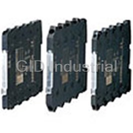
M-SYSTEMS M6NCTC
Description
M-Systems M6NCTC Screw Terminal Ultra-Slim Signal Conditioner; M6N Series; CT Transmitter (clamp-on current sensor)
Part Number
M6NCTC
Price
Request Quote
Manufacturer
M-SYSTEMS
Lead Time
Request Quote
Category
TBD
Specifications
Accuracy
±0.5 % with input 5 – 100 %
Applicable wire siz
0.2 – 2.5 mm2
Dielectric strength
2000 V AC @1 minute (input to output to power to ground)
Housing material
Flame-resistant resin (black)
Input and output
M3 screw terminal (torque 0.5 N•m)
Insulation resistance
Greater than or equal to 100 M Omega with 500 V DC
Isolation
Input to output to power
Line voltage effect
±0.1 % over voltage range
Mounting
Installation Base (model-M6NBS) or DIN rail
Operating humidity
30 to 90 %RH (non-condensing)
Operating temperature
-20 to +55°C (-4 to +131°F)
Power consumption
Approx. 0.5 W
Power input
Via the Installation Base (model- M6NBS) or M3 screw terminal (torque 0.5 N•m)
Power LED
Green light turns on when the power is supplied.
Recommended solder-less terminal
Max. 5.8 mm (0.23”) wide; Ones with insulation sleeve do not fit.
Response time
Less than or equal to 1 sec. (0 – 90 %)
RMS sensing
Up to 15 % of 3rd harmonic content
Span adjustment
98 to 102 % (front)
Temp. coefficient
±0.015 %/°C (±0.008 %/°F)
Weight
60 g (2.1 oz)
Zero adjustment
-2 to +2% (front)
Features
- 7.5-mm wide ultra-slim design
- Converts AC current signal into a low-ripple standard process signal suitable to be handled for computer inputs
- High-density mounting
- Low profile allows the M6N module mounted in a 120-mm deep panel
- Power indicator LED
Datasheet

Extracted Text
MODEL: M6NCTC 275: 0 – 75 A AC Screw Terminal Ultra-Slim Signal Conditioners M6N Series 2100: 0 – 100 A AC 2125: 0 – 125 A AC CT TRANSMITTER 2150: 0 – 150 A AC (clamp-on current sensor) 2175: 0 – 175 A AC Functions & Features 2200: 0 – 200 A AC • Converts AC current signal into a low-ripple standard 2225: 0 – 225 A AC process signal suitable to be handled for computer inputs 2250: 0 – 250 A AC • 7.5-mm wide ultra-slim design 2300: 0 – 300 A AC • Low profile allows the M6N module mounted in a 120-mm 2350: 0 – 350 A AC deep panel 2400: 0 – 400 A AC • High-density mounting 2500: 0 – 500 A AC • Power indicator LED 2600: 0 – 600 A AC 7.5 (.30) [2] OUTPUT Current A: 4 – 20 mA DC (Load resistance 550 Ω max.) 102 D: 0 – 20 mA DC (Load resistance 550 Ω max.) (4.02) G: 0 – 1 mA DC (Load resistance 11 kΩ max.) Z: Specify current (See OUTPUT SPECIFICATIONS) Voltage 102 3: 0 – 1 V DC (Load resistance 1000 Ω min.) (4.02) 4: 0 – 10 V DC (Load resistance 10 kΩ min.) mm (inch) 5: 0 – 5 V DC (Load resistance 5000 Ω min.) 6: 1 – 5 V DC (Load resistance 5000 Ω min.) 4W: -10 – +10 V DC (Load resistance 20 kΩ min.) MODEL: M6NCTC–[1][2]–R 5W: -5 – +5 V DC (Load resistance 10 kΩ min.) 0: Specify voltage (See OUTPUT SPECIFICATIONS) ORDERING INFORMATION • Code number: M6NCTC-[1][2]-R POWER INPUT Specify a code from below for each [1] and [2]. DC Power (e.g. M6NCTC-56004W-R) R: 24 V DC • Special output range (For codes Z & 0) (Operational voltage range 24 V ±10 %, ripple 10 %p-p max.) Order Clamp-on current sensor separately. RELATED PRODUCTS [1] INPUT • Clamp-on current sensor (model: CLSB) Sensor CLSE • Clamp-on current sensor (model: CLSE) 5R5 0 – 5 A AC (Select “CLSE-x/CE” to comply with CE for the combination 550: 0 – 50 A AC with the sensor.) 5100: 0 – 100 A AC 5200: 0 – 200 A AC GENERAL SPECIFICATIONS 5400: 0 – 400 A AC Connection 5600: 0 – 600 A AC Input and output: M3 screw terminal (torque 0.5 N·m) Sensor CLSB (CE not available) Power input: Via the Installation Base (model: M6NBS) 210: 0 – 10 A AC or M3 screw terminal (torque 0.5 N·m) 215: 0 – 15 A AC Recommended solderless terminal: Max. 5.8 mm (0.23”) 220: 0 – 20 A AC wide; Ones with insulation sleeve do not fit. 230: 0 – 30 A AC Applicable wire size 0.2 – 2.5 mm2 240: 0 – 40 A AC Housing material: Flame-resistant resin (black) 250: 0 – 50 A AC Isolation: Input to output to power 260: 0 – 60 A AC http://www.m-system.co.jp/ M6NCTC SPECIFICATIONS ES-7902 Rev.4 Page 1/4 MODEL: M6NCTC Input waveform CLSB-20: 300 A continuous RMS sensing: Up to 15 % of 3rd harmonic content CLSB-40: 600 A continuous Zero adjustment: -2 to +2% (front) CLSB-60: 720 A continuous (Output code 4W, 5W: Adjustable at 0V. No output below Be sure that the input voltage is of 440 V or less. 0mA for the code D.) Span adjustment: 98 to 102 % (front) OUTPUT SPECIFICATIONS Power LED: Green light turns on when the power is supplied. • DC Current: 0 – 20 mA DC ■Recommended solderless terminal Minimum span: 1 mA 5.5 max. 4 min. Offset: Max. 1.5 times span (.22) (.16) 3.2 (.13) dia. Load resistance: Output drive 11 V max. • DC Voltage: 0 – 10 V DC Minimum span: 1 V Offset: Max. 1.5 times span Load resistance: Output drive 1 mA max.; at ≥ 1 V INPUT SPECIFICATIONS • Clamp-on current sensor CLSE INSTALLATION (Sensor model No.: AC input) Power consumption: Approx. 0.5 W CLSE-R5: 0 – 5 A Operating temperature: -20 to +55°C (-4 to +131°F) CLSE-05: 0 – 50 A Operating humidity: 30 to 90 %RH (non-condensing) CLSE-10: 0 – 100 A Mounting: Installation Base (model: M6NBS) or DIN rail CLSE-20: 0 – 200 A Weight: 60 g (2.1 oz) CLSE-40: 0 – 400 A CLSE-60: 0 – 600 A PERFORMANCE in percentage of span Frequency: 50 / 60 Hz Accuracy: ±0.5 % with input 5 – 100 % Operational range: 5 – 120 % of rating Temp. coefficient: ±0.015 %/°C (±0.008 %/°F) Overload capacity: Response time: ≤ 1 sec. (0 – 90 %) CLSE-R5: 10 A continuous Line voltage effect: ±0.1 % over voltage range CLSE-05: 60 A continuous Insulation resistance: ≥ 100 MΩ with 500 V DC CLSE-10: 120 A continuous Dielectric strength: 2000 V AC @1 minute (input to output CLSE-20: 240 A continuous to power to ground) CLSE-40: 480 A continuous CLSE-60: 720 A continuous Be sure that the input voltage is of 480 V or less. STANDARDS & APPROVALS • Clamp-on current sensor CLSB CE conformity: (Sensor model No.: AC input) EMC Directive (2004/108/EC) CLSB-05: EN 61000-6-4 (EMI) 0 – 10 A, 0 – 15 A, 0 – 20 A EN 61000-6-2 (EMS) 0 – 30 A, 0 – 40 A, 0 – 50 A CLSB-10: 0 – 60 A, 0 – 75 A, 0 – 100 A CLSB-20: 0 – 125 A, 0 – 150 A, 0 – 175 A 0 – 200 A, 0 – 225 A, 0 – 250 A CLSB-40: 0 – 300 A, 0 – 350 A, 0 – 400 A CLSB-60: 0 – 500 A, 0 – 600 A Frequency: 50 / 60 Hz Operational range: 5 – 120 % of rating Overload capacity: CLSB-05: 100 A continuous CLSB-10: 200 A continuous http://www.m-system.co.jp/ M6NCTC SPECIFICATIONS ES-7902 Rev.4 Page 2/4 5.8 max. (.23) MODEL: M6NCTC EXTERNAL VIEW (With the cover open) Power LED Zero Adj. Span Adj. DIMENSIONS unit: mm (inch) SCREWDRIVER * WIRE INSERTION ANGLE INSERTION ANGLE : approx. 35° : approx. 55° 8–M3 SCREW TERMINAL DIN RAIL HOOK 5 6 7 8 DIN RAIL 35mm wide 1 2 3 4 [1 (.04)] SCREWDRIVER INSERTION ANGLE : approx. 40° 7.5 (.30) 102 (4.02) *Screwdriver stem diameter: 6 mm (.24”) or less • When mounting, no extra space is needed between units. http://www.m-system.co.jp/ M6NCTC SPECIFICATIONS ES-7902 Rev.4 Page 3/4 102 (4.02) MODEL: M6NCTC SCHEMATIC CIRCUITRY & CONNECTION DIAGRAM SOURCE Z S Isolation k Low Drift RMS Output 1 5 + Amplifier Operation Driver CLAMP-ON SENSOR OUTPUT 2 6 – l POWER LED 3 + LOAD 7 POWER 4 – 8 POWER Specifications are subject to change without notice. http://www.m-system.co.jp/ M6NCTC SPECIFICATIONS ES-7902 Rev.4 Page 4/4 CONNECTOR
Frequently asked questions
What makes Elite.Parts unique?

What kind of warranty will the M6NCTC have?
Which carriers does Elite.Parts work with?
Will Elite.Parts sell to me even though I live outside the USA?
I have a preferred payment method. Will Elite.Parts accept it?
Why buy from GID?

Quality
We are industry veterans who take pride in our work

Protection
Avoid the dangers of risky trading in the gray market

Access
Our network of suppliers is ready and at your disposal

Savings
Maintain legacy systems to prevent costly downtime

Speed
Time is of the essence, and we are respectful of yours
Related Products
Request a Quote

The quote request has been received
Close

Facing challenges or have inquiries? Feel free to contact us!
Call Us +1-469-283-2440
What they say about us
FANTASTIC RESOURCE
One of our top priorities is maintaining our business with precision, and we are constantly looking for affiliates that can help us achieve our goal. With the aid of GID Industrial, our obsolete product management has never been more efficient. They have been a great resource to our company, and have quickly become a go-to supplier on our list!
Bucher Emhart Glass
EXCELLENT SERVICE
With our strict fundamentals and high expectations, we were surprised when we came across GID Industrial and their competitive pricing. When we approached them with our issue, they were incredibly confident in being able to provide us with a seamless solution at the best price for us. GID Industrial quickly understood our needs and provided us with excellent service, as well as fully tested product to ensure what we received would be the right fit for our company.
Fuji
HARD TO FIND A BETTER PROVIDER
Our company provides services to aid in the manufacture of technological products, such as semiconductors and flat panel displays, and often searching for distributors of obsolete product we require can waste time and money. Finding GID Industrial proved to be a great asset to our company, with cost effective solutions and superior knowledge on all of their materials, it’d be hard to find a better provider of obsolete or hard to find products.
Applied Materials
CONSISTENTLY DELIVERS QUALITY SOLUTIONS
Over the years, the equipment used in our company becomes discontinued, but they’re still of great use to us and our customers. Once these products are no longer available through the manufacturer, finding a reliable, quick supplier is a necessity, and luckily for us, GID Industrial has provided the most trustworthy, quality solutions to our obsolete component needs.
Nidec Vamco
TERRIFIC RESOURCE
This company has been a terrific help to us (I work for Trican Well Service) in sourcing the Micron Ram Memory we needed for our Siemens computers. Great service! And great pricing! I know when the product is shipping and when it will arrive, all the way through the ordering process.
Trican Well Service
GO TO SOURCE
When I can't find an obsolete part, I first call GID and they'll come up with my parts every time. Great customer service and follow up as well. Scott emails me from time to time to touch base and see if we're having trouble finding something.....which is often with our 25 yr old equipment.
ConAgra Foods