

 Manufacturers
LIPPERT 903-0023-10

Description
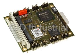
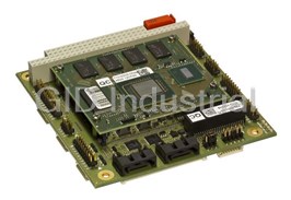
Lippert 903-0023-10 CPU Board. Cool RoadRunner 945GSE | Intel Atom N270 (1.6Ghz) Processor | 2GB DDR2-RAM | SXGA: 2048 x 1536 pixel | CRT and LVDS | Gigabit Ethernet | 8 x USB 2.0 | 2 x RS232/RS422/RS485 | 2 GB Solid State Disk | HD audio 2 x SATA | PC/104+ | Extended Temperature Range of -40C to +85C | Heat Spreader
Part Number
903-0023-10
Price
Request Quote
Manufacturer
LIPPERT
Lead Time
Request Quote
Category
PRODUCTS - 9
Features
- 2 GB Solid State Disk
- 2 x SATA
- 8 x USB 2.0, 2 x RS232/RS422/RS485
- Gigabit Ethernet
- HD audio
- Intel Atom N270 Processor
- SXGA 2048 x 1536 pixel, CRT and LVDS
- Up to 2 Gbyte soldered DDR2-RAM
Datasheet

Extracted Text
Cool RoadRunner-945GSE
PC/104-Plus CPU Board
Technical Manual
TME-104P-CRR-945GSE-2V6
Revision 2.6 / March 10
©
LiPPERT Embedded Computers GmbH
Hans-Thoma-Str. 11
D-68163 Mannheim
http://www.lippertembedded.com/
Technical Manual Cool RoadRunner-945GSE
LiPPERT Document: TME-104P-CRR-945GSE-2V6.doc, Revision 2.6
Copyright © 2009 LiPPERT Embedded Computers GmbH, all rights reserved
Contents and specifications within this manual are subject of change without notice.
Trademarks
MS-DOS, Windows XP are trademarks of Microsoft Corporation. Inc. Intel is a trademark of Intel Corporation. PC/104
is a registered trademark of PC/104 Consortium. All other trademarks appearing in this document are the property of
their respective owners.
TME-104P-CRR-945GSE-2V6 Rev 2.6
Table of Contents
1 Overview 1
1.1 Introduction ......................................................................................................................... 1
Features .....................................................................................................................................1
Block Diagram ............................................................................................................................2
1.2 Ordering Information ............................................................................................................ 3
Cool RoadRunner-945GSE Models ............................................................................................3
Cable Sets and Accessories .......................................................................................................3
1.3 Specifications ...................................................................................................................... 4
Electrical Specifications ..............................................................................................................4
Environmental Specifications ......................................................................................................4
MTBF .........................................................................................................................................4
1.4 Mechanical .......................................................................................................................... 5
TOP ...........................................................................................................................................6
BOTTOM (vertical mirrored) ........................................................................................................7
2 Getting Started 8
2.1 Connector Locations ............................................................................................................ 8
Top ............................................................................................................................................8
Bottom .......................................................................................................................................9
2.2 Jumper Locations .............................................................................................................. 10
Top ......................................................................................................................................... 10
Bottom .................................................................................................................................... 11
2.3 LED indicators ................................................................................................................... 12
2.4 Hardware Setup................................................................................................................. 13
3 Module Description 14
3.1 Processor .......................................................................................................................... 14
3.2 Graphics and Memory Controller Hub ................................................................................. 14
3.3 System Memory ................................................................................................................. 15
3.4 Internal Graphics ................................................................................................................ 15
VGA ........................................................................................................................................ 16
LVDS ....................................................................................................................................... 17
LVDS Color Mapping............................................................................................................... 18
TME-104P-CRR-945GSE-2V6 Rev 2.6 i
Backlight ................................................................................................................................. 18
Display Voltage Jumpers ......................................................................................................... 19
3.5 I/O Controller Hub - Mobile ................................................................................................. 20
Serial ATA ............................................................................................................................... 21
SSD on IDE ............................................................................................................................. 22
HD-Audio ................................................................................................................................ 23
USB ........................................................................................................................................ 24
BIOS Recovery Connector ...................................................................................................... 25
PC/104-Plus Bus Interface ...................................................................................................... 26
PC/104 Bus Interface .............................................................................................................. 27
PC/104 Bus Connector ........................................................................................................... 27
3.6 CPU Fan Connector ........................................................................................................... 29
3.7 Gigabit Ethernet Controller ................................................................................................. 29
3.8 On Board Power Supply ..................................................................................................... 30
Power Connector .................................................................................................................... 30
3.9 Serial Ports ........................................................................................................................ 31
COM Connector ...................................................................................................................... 31
RS485-Termination Jumpers................................................................................................... 32
3.10 System Panel Connector .................................................................................................... 33
SMB/I²C .................................................................................................................................. 33
Power Button .......................................................................................................................... 33
Reset Button ........................................................................................................................... 33
HDD LED ................................................................................................................................ 33
External Battery ....................................................................................................................... 33
3.11 BIOS Recovery .................................................................................................................. 34
4 Using the Module 35
4.1 Watchdog ......................................................................................................................... 35
4.2 LEMT functions .................................................................................................................. 35
4.3 BIOS ................................................................................................................................. 36
Boot Menu .............................................................................................................................. 36
Jumper Battery ....................................................................................................................... 37
Configuring the BIOS............................................................................................................... 37
Field Selection ......................................................................................................................... 38
Troubleshooting the BIOS ....................................................................................................... 38
Standard CMOS Features ....................................................................................................... 39
TME-104P-CRR-945GSE-2V6 Rev 2.6 ii
Advanced Bios Features ......................................................................................................... 40
CPU Features .......................................................................................................................... 41
Hard Disk BOOT Priority .......................................................................................................... 41
Advanced Chipset Features .................................................................................................... 42
Integrated Peripherals ............................................................................................................. 42
OnChip IDE Device .................................................................................................................. 43
IT8888 Configuration ............................................................................................................... 44
ISA Decode I/O ....................................................................................................................... 45
ISA Decode Memory ............................................................................................................... 46
Super IO Device ...................................................................................................................... 47
USB Device setting ................................................................................................................. 47
Power Management Setup ...................................................................................................... 48
PnP/PCI Configurations ........................................................................................................... 49
Frequency voltage control ....................................................................................................... 50
4.4 Programming Examples ..................................................................................................... 51
LIVE-LED................................................................................................................................. 51
Reading Voltages .................................................................................................................... 52
Reading Ambient Temperature ................................................................................................ 53
4.5 Drivers ............................................................................................................................... 53
5 Address Maps 54
5.1 Memory Address Map ........................................................................................................ 54
5.2 I/O Address Map ............................................................................................................... 55
5.3 Interrupts ........................................................................................................................... 56
5.4 DMA Channels ................................................................................................................... 57
Appendix A, Contact Information A
Appendix B, Additional Information B
Appendix C, Getting Help C
Appendix D, Revision History D
TME-104P-CRR-945GSE-2V6 Rev 2.6 iii
Acronyms
AHCI Advanced Host Controller Interface
ACPI Advanced Configuration and Power Management Interface
AES Advanced Encryption Standard
APM Advanced Power Management
ATA Advanced Technology Attachment
BIOS Basic Input Output System
BPP Bits Per Pixel
CD Compact Disc
COM Communication Equipment
CPU Central Processing Unit
CRT Cathode Ray Tube
DAC Digital-to-Analog-Converter
DC Direct Current
DDR Double Date Rate
DMA Direct Memory Access
DMI Direct Media Interface
DOT Dynamic Overclocking Technology
EIDE Enhanced Integrated Device Electronics
EMC Electromagnetic Compatibility
ETH Ethernet
FIFO First In First Out
FPU Floating Point Unit
FWH Firmware Hub
FSB Front Side Bus
GPIO General Purpose Input Output
HDD Hard Disk Drive
HDA High Density Audio
I²C Inter-Integrated Circuit
IP Internet Protocol
ISA Industry Standard Architecture
LCD Liquid Crystal Display
LED Light Emitting Diode
LEMT LiPPERT Enhanced Management Technology
LFP Large Format Printing
LPC Low Pin Count
LVDS Low Voltage Differential Signaling
MAC Media Access Control
MMU Memory Management Unit
PCI Peripheral Component Interconnect
PHY Physical Interface
PLL Phase-Locked Loop
PWM Pulse Width Modulation
PWR Power
ROM Read Only Memory
SATA Serial Advanced Technology Attachment
SMB System Management Bus
SMC System Management Controller
SPI Serial Peripheral Interface
SSD Solid State Drive
SVGA Super Video Graphics Array
TCP Transmission Control Protocol
UART Universal Asynchronous Receiver Transmitter
USB Universal Serial Bus
UDMA Ultra-Direct Memory Access
UDP User Datagram Protocol
VGA Video Graphics Array
WDOG Watchdog
TME-104P-CRR-945GSE-2V6 Rev 2.6 iv
1 Overview
1.1 Introduction
The Cool RoadRunner-945GSE is a CPU-board with a Mobile Intel Atom™ N270 processor with a good performance
power ratio.
The board comprises all peripherals needed for an embedded PC on a small 4.55" by 3.78" printed circuit board.
TM
The Cool RoadRunner-945GSE integrates a powerful yet efficient Mobile Intel ATOM processor together with a
945GSE- and an ICH7M- chipset to form a complete PC, with all the standard peripherals already onboard. There is a
graphics controller with 2D and 3D support. For analog monitors there is a VGA-interface and digital ones can be
connected to LVDS. Backlighting is provided for LCD modules too.
One Gigabit Ethernet port, two RS232/RS485 serial ports, and eight USB 2.0 host ports handle the communication
with external devices.
The IDE ATA100 controller is connected to the mounted 2 Gbyte Solid State Disk.
Another hard- or DVD/CD-ROM- drives can be connected to two SATA ports.
System expansion can easily be realized over PC/104, PC/104-Plus and I²C bus connectors.
The Cool RoadRunner-945GSE is powered by a 5V-only power supply and supports ACPI, advanced power
management and PCIe power management.
The Cool RoadRunner-945GSE runs at DOS, Linux, Windows XP, Windows CE 6.0 R3, Windows XP Embedded as
well as QNX 6.4.1 .
Features
CPU Main Memory
TM
• Intel ATOM N270 1,6 GHz • 0,5/1/2 GByte DDR2 533 MHz RAM
• 533 MHz FSB
• 512 KB L2 Cache Size
• Hyper-Threading Technology
• Intel Speedstep® Technology
Chipset Extension slots
• Northbridge Intel 945GSE • 1 x 32-bit PC/104-Plus
• Southbridge Intel ICH7-M • 1 x 16-bit PC/104 with full DMA capability
Interfaces Other Features
• Ethernet 10/100/1000 MBit/s • Onboard Microcontroller with LEMT (LiPPERT
Enhanced Management Technology)
• 2 GByte SSD on EIDE
• Onboard Power supply for all necessary voltages
• 2 x Serial ATA
• 8 x USB 2.0 ports • 5V single power supply
• HD Audio Controller • I²C bus and status LED
• 18 Bit single-channel LVDS for displays
• Analog VGA with DDC
• 2 x RS232/RS485, software selectable
Other configurations are possible. Please contact your local LiPPERT representative to discuss requirements.
TME-104P-CRR-945GSE-2V6 Rev 2.6 1(57)
Block Diagram
Intel
ATOM
N270
VGA
IDC 10
2.00 mm
Intel
LVDS
DDR2 533 MHz
82945GSE
DF14 30 pin
(GMCH)
Backlight
DF13 8 pin
SMC
System-
2 x USB
Panel
SMB USB
DF13 8 pin
IDC 10
2.00 mm
Gb-Ethernet
2 x USB
SMB
MAC/PHY PCIe USB
DF13 8 pin
IDC 10
2.00 mm
SATA
2 x USB
7 pin Header USB
DF13 8 pin
1.27 mm
Intel
SATA
2 x USB
7 pin Header USB
82801GBM
DF13 8 pin
1.27 mm
(ICH7M)
HD Audio
Audio
HDA SPI SPI-Flash
IDC 16
Codec
2.00 mm
Recovery
SSD EIDE
BIOS
DF13 10 pin
COM1
RS232/485
PC/104+ PCI
IDC 10
2.00 mm
Super I/O
COM2
RS232/485
IDC 10
PC/104 2.00 mm
ISA PCI -> ISA
CRR-ATOM PC/104_PLUS-
Diagram rev0v2 01092008CS
TME-104P-CRR-945GSE-2V6 Rev 2.6 2(57)
LPC
DMI FSB
1.2 Ordering Information
Cool RoadRunner-945GSE Models
Order number Description
703-0021-10 CRR-945GSE with 512MB DDR2 RAM
Operating temp. range: 0°C…+60°C
803-0021-10 CRR-945GSE with 512MB DDR2 RAM
Operating temp. range: -20°C…+60°C
903-0021-10 CRR-945GSE with 512MB DDR2 RAM
Operating temp. range: -40°C…+85°C
703-0022-10 CRR-945GSE with 1GB DDR2 RAM
Operating temp. range: 0°C…+60°C
803-0022-10 CRR-945GSE with 1GB DDR2 RAM
Operating temp. range: -20°C…+60°C
903-0022-10 CRR-945GSE with 1GB DDR2 RAM
Operating temp. range: -40°C…+85°C
703-0023-10 CRR-945GSE with 2GB DDR2 RAM
Operating temp. range: 0°C…+60°C
803-0023-10 CRR-945GSE with 2GB DDR2 RAM
Operating temp. range: -20°C…+60°C
903-0023-10 CRR-945GSE with 2GB DDR2 RAM
Operating temp. range: -40°C…+85°C
Cable Sets and Accessories
There are some options available for the Cool RoadRunner-945GSE. Please check their availability before ordering.
Order number Description
863-0017-10 Adapter Cable Set
Power, GBit-Ethernet, VGA-CRT, 4x USB (double), 1x COM (double), HD-Audio
765-0025-10 Heat sink passive CRR-945GSE
TME-104P-CRR-945GSE-2V6 Rev 2.6 3(57)
1.3 Specifications
Electrical Specifications
+5 V DC
Supply voltage 1
Rise time < 10 ms
Supply voltage tolerance ± 5%
Inrush current 5.7 A
maximum 2.5 A depending on operating system and connected peripherals
Supply current 2
typical 1.9 A (Windows XP idle mode)
typical 100 mA (suspend to ram mode)
Environmental Specifications
Operating:
Temperature range 0 … 60 °C (standard version)
-20 … 60 °C (industrial version)
-40 … 85 °C (extended version)
Temperature change 10K / 30 minutes maximum
Humidity (relative) 10 … 90 % (non-condensing)
Pressure 450 … 1100 hPa
Non-Operating/Storage/Transport:
-40 … 85 °C
Temperature range 3
Temperature change 10K / 30 minutes maximum
Humidity (relative) 5 … 95 % (non-condensing)
Pressure 450 … 1100 hPa
MTBF
MTBF at 25°C 159 899 hours
1 The specified tolerance does not guarantee that peripheral boards will work. Refer to their documentation for their
specific requirements.
2 Measured with monitor, mouse and keyboard attached.
3 When the board is stored longer times under higher temperature conditions, the life time of the battery is reduced
TME-104P-CRR-945GSE-2V6 Rev 2.6 4(57)
1.4 Mechanical
Dimensions (L x W) 115.6 mm x 95.9 mm (including I/O extension)
Height max. 14 mm on topside above PCB
max. 12 mm on bottom side above PCB
Weight typ. 115 gr. with 1024 MB RAM and without heat sink
Mounting 4 mounting holes
Note: It is strongly recommend using plastic spacers instead of metal spacers to mount the
board. With metal spacers, there is a possible danger to create a short circuit with the
components located around the mounting holes. This can damage the board!
TME-104P-CRR-945GSE-2V6 Rev 2.6 5(57)
TOP
Pin1 Pin2
TME-104P-CRR-945GSE-2V6 Rev 2.6 6(57)
BOTTOM (vertical mirrored)
Pin1 Pin2
TME-104P-CRR-945GSE-2V6 Rev 2.6 7(57)
2 Getting Started
2.1 Connector Locations
Top
COM1/COM2
SATA0 SATA1
X8
X2 X5
PC/104
PC/104
Plus X18
X17
PWR
X19
Ethernet VGA System Panel
Audio
X13 Fan X15
X3 X14
X8
The connectors' pin 1 is marked RED
TME-104P-CRR-945GSE-2V6 Rev 2.6 8(57)
Backlight
Bottom
USB 0/1 USB 2/3
USB 4/5 USB 6/7
X24 X26
X28 X31
PC/104
PC/104
X18
Plus
X17
BIOS
Recovery
X4
Backlight
LVDS
X27 X25
The connectors' pin 1 is marked RED
TME-104P-CRR-945GSE-2V6 Rev 2.6 9(57)
Jumper X5
2.2 Jumper Locations
Top
Jumper
RS485 termination
X16
Jumper
CMOS Reset
X32
Jumper
Battery
X30
The connectors' pin 1 is marked RED
TME-104P-CRR-945GSE-2V6 Rev 2.6 10(57)
Bottom
Jumper
Display voltage
selection
LVDS and Backlight
X11
The connectors' pin 1 is marked RED
TME-104P-CRR-945GSE-2V6 Rev 2.6 11(57)
2.3 LED indicators
The onboard LED indicators provide a very comfortable way to check the board’s status. The boot success, power
status, IDE accesses, Watchdog and Ethernet accesses are all visible.
The LED indicators are located on top of the board, near the PC/104 connector.
100M Yellow LED lights up if there is a 100Mbit connection
ACT Red LED lit if link is established and flashes at Ethernet activity.
1G Yellow LED lights up if there is a 1Gbit connection
MAIN Green LED lights up when Main Power is supplied.
PM Power Mode
Green LED is constantly lit if the boot process is complete and
the board is running normally.
Red LED flashes when board goes in suspend to ram mode.
SBY Green LED lights up when Standby Power is supplied.
LIVE The user programmable LED is on at startup when the board
transfers data from the bios.
Chapter "LIVE-LED" shows a small program how to get
access for activation.
HDD Yellow LED flashes when SATA and EIDE activity is
recognized.
The low-active signal can also be found at the system panel
connector, see chapter 3.10.
WD Red LED lights up when Watchdog is active. Can only be reset by powering off the board.
The low-active signal is located at the system panel connector too, see chapter 3.10.
TME-104P-CRR-945GSE-2V6 Rev 2.6 12(57)
2.4 Hardware Setup
Caution Be sure to observe the EMC security measures. Make sure you are always at the
same potential as the module.
Caution Never connect or disconnect peripherals like PCI and ISA while the board's power
supply is connected and switched on!
Use the cable set provided by LiPPERT to connect the Cool RoadRunner-945GSE to a VGA monitor. Connect USB
keyboard and mouse, respectively. Use the soldered SSD or connect a hard drive with a SATA cable (not part of the
cable set) to start an operation system. Make sure that the pins match their counterparts correctly and are not twisted!
If you plan to use additional other peripherals, now is the time to connect them, too.
Set the “Jumper Battery” that it has contact with both pins. The location can be found on chapter 2.2.
Connect a 5 volt power supply to the power connector and switch the power on.
Note In continuous mode, no more than 2.5 amps are required.
However, at power-on, approximately 6 A are drawn for a short time.
This inrush current will increase when peripherals are added.
The display shows the BIOS messages. If you want to change the standard BIOS settings, press the "Delete" key to
enter the BIOS menu. See chapter 4.3 for setup details.
If you need to load the BIOS default values, they can be automatically loaded at boot time. See chapter 4.3,
Troubleshooting the BIOS about how to do it.
The Cool RoadRunner-945GSE boots from SSD, DVD/CD-ROM drives, LAN, USB floppy, USB mass storage, USB-
hard drive or SATA hard disk. Provided that any of these is connected and contains a valid operating system image,
the display then shows the boot screen of your operating system.
The Cool RoadRunner-945GSE needs additional cooling measures. Depending on the required temperature range,
different cooling solutions are available.
TME-104P-CRR-945GSE-2V6 Rev 2.6 13(57)
3 Module Description
3.1 Processor
The Intel® Atom™ Processor N270 is built on 45-nanometer process technology — the first generation of low-power
IA-32 micro architecture.
® ®
The processor supports Intel 945GSE chipset with the I/O Controller Hub 7 - Intel 82801GBM.
Major feature
The following list provides some of the key features on this processor:
• On-die primary 32-kB instructions cache and 24-kB write-back data cache
• 533-MHz source-synchronous front side bus (FSB)
• 2-Threads support
• On-die 512-kB, 8-way L2 cache
• Support for IA 32-bit architecture
• Intel® Streaming SIMD Extensions-2 and -3 (Intel® SSE2 and Intel® SSE3)
support and Supplemental Streaming SIMD Extension 3 (SSSE3) support
• Thermal management support via Intel® Thermal Monitor
• Supports C0/C1(e)/C2(e)/C4(e) states
• L2 Dynamic Cache Sizing
• Advanced power management features including Enhanced Intel Speedstep® Technology
• Execute Disable Bit support for enhanced security
3.2 Graphics and Memory Controller Hub
The Mobile Intel 945GSE Chipset comes with the Generation 3.5 Intel Integrated Graphics Engine, and the
Intel® Graphics Media Accelerator 950 (Intel® GMA 950), providing enhanced graphics support over the previous
generation Graphics and Memory Controller Hubs ((G) MCH).
The (G)MCH manages the flow of information between the four following primary interfaces:
• FSB
• System Memory Interface
• Graphics Interface
• DMI
TME-104P-CRR-945GSE-2V6 Rev 2.6 14(57)
3.3 System Memory
• Memory supported: 512 MB, 1 GB and 2 GB @ 533 MHz
• Densities supported: 1 Gbit and 2 Gbit
• 64-bit wide per channel
• 8 internal banks for concurrent operation
• Dual-channel DDR2 SDRAM
• Memory Channel Configurations supported:
o Dual-Channel Symmetric
o Dual-Channel Asymmetric
• Intel® Rapid Memory Power Management (Intel® RMPM)
• Partial Writes to memory using Data Mask signals (DM)
• 64 ms, 8,192-cycle refresh
• Dynamic row power-down
• On-die termination (ODT)
3.4 Internal Graphics
• Intel® Gen 3.5 Integrated Graphics Engine
• 250 MHz core render clock and 200 MHz core display clock at 1.05 core voltage
• Dynamic Video Memory Technology (DVMT 3.0)
• Intel® Display Power Saving Technology 2.0 (Intel® DPST 2.0)
• Intel® Smart 2D Display Technology (Intel® S2DDT)
• Intel® Automatic Display Brightness
• 4x pixel rate HWMC
• Microsoft DirectX* 9.1 operating system
• Intermediate Z in Classic Rendering
• Internal Graphics Display Device States: D0, D1, D3
TME-104P-CRR-945GSE-2V6 Rev 2.6 15(57)
VGA
The analog display port provides a RGB signal output along with a HSYNC and VSYNC signal.
There is an associated DDC signal pair that is implemented using GPIO pins dedicated to the analog port. The
intended target device is for a CRT based monitor with a VGA connector.
Display devices such as LCD panels with analog inputs may work satisfactory but no functionality has been added to
the signals to enhance that capability.
The display function contains a RAM-based Digital-to-Analog Converter (RAMDAC) that transforms the digital data
from the graphics and video subsystems to analog data for the CRT monitor. (G)MCH integrated 400 MHz RAMDAC
supports resolutions up to 2048 x 1536. Three 8-bit DAC provide the R, G, and B signals to the monitor.
Connector type IDC10 pin header 2.00 mm
Article number 862-0019-10
Pin Signal Pin Signal
1 Red 2 Video-GND
3 Green 4 key
5 Blue 6 DDCCLK
7 H-Sync 8 DDCDAT
9 V-Sync 10 GND
X15
TME-104P-CRR-945GSE-2V6 Rev 2.6 16(57)
LVDS
The GMCH has a dedicated single channel LFP transmitter to support resolutions up to
UXGA (1600 x 1200). The frequency range works between 25-MHz to 112-MHz
Depending on configuration and mode, the single channel can take 18 bits of RGB pixel data plus
3 bits of timing control (HSYNC/VSYNC/DE) and output them on three differential data pair outputs.
This display port is normally used in conjunction with the pipe functions of panel scaling and
6-to 8-bit dither. This display port is also used in conjunction with the panel power sequencing and additional
associated functions. In case of an unscaled mode the display is centered on the panel.
Connector type DF14 1x 30-pin header
Pin Signal
4
1
VDD (3.3 V, opt.5 V)
4
2
VDD (3.3 V, opt.5 V)
3 GND
4 GND
5 n.c.
6 n.c.
7 TXACLK -
8 TXACLK +
9 GND
10 TXA2 -
11 TXA2 +
12 TXA1 -
13 TXA1 +
14 TXA0 -
15 TXA0 +
X27
16 GND
17 n.c.
18 n.c.
19 n.c.
20 n.c.
21 GND
22 n.c.
23 n.c.
24 n.c.
25 n.c.
26 n.c.
27 n.c.
28 GND
29 LVDS DDC-CLK
30 LVDS DDC-DATA
4
1.0 A is the maximum current for each pin
TME-104P-CRR-945GSE-2V6 Rev 2.6 17(57)
LVDS Color Mapping
Backlight
In order to meet the panel power timing specification requirements the LCD backlight inverter power supply is
controlled by an integrated PWM interface.
Connector type DF13 1x 8-pin header
Pin Signal
1
5
+12 Volt
2 5
+12 Volt
3
5
+5 Volt
4 5
X25
+5 Volt
5
CTRL
6
6
EN
7
GND
8
GND
5
0.5 A is the maximum current for each pin
6
That voltage can be selected over Jumper Backlight, shown on next page
TME-104P-CRR-945GSE-2V6 Rev 2.6 18(57)
Display Voltage Jumpers
Jumper LVDS and Backlight
Connector type IDC6 jumper 2.00 mm.
Use a 2 mm jumper between 1-3 or 3-5 to select the display voltage.
Use a 2 mm jumper between 2-4 or 4-6 to select the backlight voltage.
Pin Signal Pin Signal
1 +3.3 Volt 2 +12 Volt
3 Display voltage 4 Backlight voltage
X11
5 + 5 Volt 6 +5 Volt
default jumper setting
LVDS
Jumper 1-3 3-5
Power supply +3.3V +5V
Backlight
Jumper 2-4 4-6
Power supply +12V +5V
Note An arrow marks Pin 1
TME-104P-CRR-945GSE-2V6 Rev 2.6 19(57)
3.5 I/O Controller Hub - Mobile
The ICH7-M provides extensive I/O support.
Functions and capabilities include:
• PCI Local Bus Specification, Revision 2.3 support for 33 MHz PCI operations
• ACPI Power Management Logic Support
• Enhanced DMA controller, interrupt controller, and timer functions
• Integrated Serial ATA host controller with independent DMA operation on two ports
• Integrated IDE controller supports Ultra ATA100
• USB host interface with support of eight USB ports; four UHCI host controllers;
one EHCI high-speed USB 2.0 Host controller
• System Management Bus (SMBus) Specification, Version 2.0 with additional support for I2C devices
• Intel High Definition Audio
• Low Pin Count (LPC) interface
• Firmware Hub (FWH) interface
• Serial Peripheral Interface (SPI) support
TME-104P-CRR-945GSE-2V6 Rev 2.6 20(57)
Serial ATA
The ICH7 has an integrated SATA host controller that supports independent DMA operation on two ports and supports
data transfer rates of up to 300 MB/s. The SATA controller contains two modes of operation – a legacy mode using I/O
space, and an AHCI mode using memory space.
SATA and PATA can also be used in a combined function mode
(where the SATA function is used with PATA).
In this combined function mode, AHCI mode is not used. Software that uses legacy mode will not have AHCI
capabilities.
The ICH7 supports the Serial ATA Specification, Revision 1.0a. The ICH7 also supports several optional sections of the
Serial ATA II:
Extensions to Serial ATA 1.0 Specification, Revision 1.0 (AHCI support is required for some elements).
Platforms supporting AHCI may take advantage of performance features such as no master/slave designation for SATA
devices. Each device is treated as a master and hardware-assisted with native command queuing. AHCI also provides
usability enhancements such as Hot-Plug. AHCI requires appropriate software support (e.g., an AHCI driver) and for
some features, hardware support in the SATA device or additional platform hardware.
There are two connectors with the same type and pin assignment, which support standard SATA cables and SATA
cables with mechanical latch:
Connector type 1.27 mm Pitch Serial ATA High Speed Header, Vertical with Latch support
Pin Signal
1
GND
2
TX+
3
TX-
4
GND
5
RX-
6
RX+
X2, X5
7
GND
Note If a hard drive and a CD/DVD drive are connected at the same time, it could be possible
that the Cool RoadRunner-945GSE does not boot from the CD/DVD.
In that case a firmware update of the CD/DVD drive is required.
However, there might be drives that cannot be used to boot a system, even after
updating.
TME-104P-CRR-945GSE-2V6 Rev 2.6 21(57)
SSD on IDE
On the top side of the board there is the SSD mounted. It can be used instead of a hard disk. There is no other IDE
device connectable, the SSD it set as master.
The SSD, made by Silicon Storage Technology, Inc., is built as a flash storage organized of Single Level Cells (SLC).
The SLC technology has more stability as the commercial Multi Level Cells (MLC).
It can be erased over 100M times without losing capacity. The wear-leveling feature increases that number, depending
on the allocation of the disk space.
The offered variant has a capacity of 2 GByte. Bigger sizes are available on request at higher quantities.
Product features:
Read Bandwidth 30 Mbytes/s
Write Bandwidth 20 Mbytes/s
Access time 0.6 ms
PATA Compatibility ATA-5; PIO 0-4; DMA 0-2; UDMA 0-4
Power Control Automatic power down during wait periods
Automatic sleep mode during host inactivity
NAND Management Active wear-leveling algorithm
TME-104P-CRR-945GSE-2V6 Rev 2.6 22(57)
HD-Audio
The ICH7 provides a HD-Audio link to connect a codec where those features can be used.
The following I/O's are used by the Cool RoadRunner-945GSE:
• Analog Input (All ADC support 44,1k/48k/96kHz sampling rate)
o Microphone left and right
o Line In left and right
• Analog output (All DAC support 44,1k/48k/96/192kHz sampling rate)
o Front left and right
o Rear left and right
o Center and Subwoofer
• Digital input (16/20/24-bit S/PDIF-in support 44,1k/48k/96/192kHz sampling rate)
o S/PDIF
• Digital output (16/20/24-bit S/PDIF-out support 44,1k/48k/96/192kHz sampling rate)
o S/PDIF
Connector type IDC16 pin header 2.00 mm
Article number 862-0065-10
Pin Signal Pin Signal
1 FRONT_L 2 FRONT_R
3 SURR_L 4 SURR_R
5 CENTER 6 LFE
7 GND_AU 8 GND_AU
9 LINE_IN_L 10 LINE_IN_R
11 MIC_L 12 MIC_R
13 GND 14 GND
X3
15 SPDIF_IN 16 SPDIF_OUT
TME-104P-CRR-945GSE-2V6 Rev 2.6 23(57)
USB
The ICH7 contains one Enhanced Host Controller Interface (EHCI) host controller which supports up to eight USB 2.0
high-speed ports. USB 2.0 allows data transfers up to 480 Mb/s using the same pins as the eight USB full-speed/low-
speed ports. The ICH7 contains port-routing logic that determines whether a USB port is controlled by one of the UHCI
controllers or by the EHCI controller. Onboard are four connectors with two ports on each of them.
USB-Port-Connections
USB0 USB1 USB2 USB3 USB4 USB5 USB6 USB7
USB 1.1 USB 1.1 USB 1.1 USB 1.1
Controller Controller Controller Controller
USB 2.0 Controller
The bandwidth of USB 2.0 is shared by all eight ports. If more than one USB 2.0 device is connected, the maximum
data rate will not be available.
Connector type DF13 8 pin header 1.25 mm
Article number 862-0058-10
Pin Primary Signal
7
1
VCC_USB0
2 USB0-
3 USB0+
X24, X26,
4 USB-GND
X28, X31
5 USB-GND
6 USB1-
7 USB1+
7
8
VCC_USB1
Note: Wake events from USB only work on USB ports 0 and 1
No other port can be used at all if wake events are to be used, not even for other
purposes. The other ports must remain unconnected.
7
0.5 A is the maximum current for that pin
TME-104P-CRR-945GSE-2V6 Rev 2.6 24(57)
BIOS Recovery Connector
In order to recover from BIOS problems, a so-called recovery BIOS can be used. This is a special hardware unit that
can be attached to the BIOS Recovery Connector, located near the PC/104 header.
For operational details, see
Connector type DF13 10 pin header 1.25 mm
Pin Signal
8
1
+3V3
2 LAD0
3 LAD1
4 LAD2
5 LAD4
X4
6 BIOS_DISABLE#
7 LFRAME#
8 PCI_RST#
9 CLK_33_FWH_R
10 GND
8
0.3 A is the maximum current for that pin
TME-104P-CRR-945GSE-2V6 Rev 2.6 25(57)
PC/104-Plus Bus Interface
The ICH7 PCI interface provides a 33 MHz, Revision 2.3 implementation. The ICH7 integrates a PCI
arbiter that supports up to six external PCI bus masters in addition to the internal ICH7 requests. This allows for
combinations of up to six PCI down devices and PCI slots.
The PC/104-Plus bus conforms to the current PC/104 specification.
Pin Row A Row B Row C Row D
1 GND n.c. +V5A AD00
2 VI/O AD02 AD01 +V5A
3 AD05 GND AD04 AD03
4 C/BE0# AD07 GND AD06
5 GND AD09 AD08 GND
6 AD11 VI/O AD10 n.c.
7 AD14 AD13 GND AD12
8 +3V3S C/BE1# AD15 +3V3S
9 SERR# GND GND PAR
10 GND PERR# +3V3S PME#
11 STOP# +3V3S LOCK# GND
12 +3V3S TRDY# GND DEVSEL#
13 FRAME# GND IRDY# +3V3S
14 GND AD16 +3V3S C/BE2#
15 AD18 +3V3S AD17 GND
16 AD21 AD20 GND AD19
17 +3V3S AD23 AD22 +3V3S
18 IDSEL0 GND IDSEL1 IDSEL2
X17
19 AD24 C/BE3# VI/O IDSEL3
20 GND AD26 AD25 GND
21 AD29 +V5A AD28 AD27
22 +V5A AD30 GND AD31
23 REQ0# GND REQ1# VI/O
24 GND REQ2# +V5A GNT0#
25 GNT1# VI/O GNT2# GND
26 +V5A CLK0 GND CLK1
27 CLK2 +V5A CLK3 GND
28 GND INTD +V5A RST#
29 +V12A INTA INTB# INTC#
30 -V12A REQ3# GNT3# GND
Note: All VI/O pins are connected to +5 V
The voltages +5 V, +12 V and -12 V are not generated by the onboard power-
supply but they are routed from the Power Supply Connector.
The maximum current is limited, depending on voltage:
+12 V < 1 A; -12 V < 0,3 A; +5 V < 8 A; +3,3 V < 3 A
A maximum of 1 A can be drawn from each pin.
TME-104P-CRR-945GSE-2V6 Rev 2.6 26(57)
PC/104 Bus Interface
The PC/104 bus is a modification of the industry standard (ISA) PC bus specified in IEEE P996. The PC/104 bus has
different mechanics than IEEE P966 to allow the stacking of modules.
The main features are:
• Supports programmable extra wait state for ISA cycles
• Supports I/O recovery time for back-to-back I/O cycles
Note: Resources (IO or Memory space and IRQ) for PC/104 bus must be configured
in bios setup, see bios setup menu items IT8888 Configuration and PnP/PCI
Configurations
Note: -5 V on the PC/104 connector are not supported on this board.
PC/104 Bus Connector
Pin A B
1 IOCHCK GND
2 D7 RSTDRV
3 D6 +V5A
4 D5 IRQ9
5 D4 n.c.
6 D3 DRQ2
7 D2 -12V
Pin D C 8 D1 n.c.
0 GND GND 9 D0 +12V
1 MEMCS16 SBHE 10 IOCHRDY n.c.
2 IOCS16 LA23 11 AEN SMEMW
3 IRQ LA22 12 A19 SMEMR
4 IRQ LA21 13 A18 IOW
5 IRQ LA20 14 A17 IOR
6 IRQ LA19 15 A16 DACK3
7 IRQ LA18 16 A15 DRQ3
8 DACK LA17 17 A14 DACK1
9 DRQ MEMR 18 A13 DRQ1
10 DACK MEMW 19 A12 REFRESH
11 DRQ SD8 20 A11 SYSCLK
12 DACK SD9 21 A10 IRQ7
13 DRQ SD10 22 A9 IRQ6
14 DACK SD11 23 A8 IRQ5
15 DRQ SD12 24 A7 IRQ4
16 +V5A SD13 25 A6 IRQ3
17 MASTER SD14 26 A5 DACK2
18 GND SD15 27 A4 TC
19 GND GND 28 A3 BALE
X18
29 A2 +V5A
30 A1 OSC
31 A0 GND
32 GND GND
Note: The voltages +5 V, +12 V and -12 V are not generated by the onboard power-
TME-104P-CRR-945GSE-2V6 Rev 2.6 27(57)
supply but they are routed from the Power Supply Connector.
The maximum current is limited depending on voltage:
+12 V < 1 A; -12 V < 0,3 A; +5 V < 3 A
One pin can be used for 1 A at maximum.
TME-104P-CRR-945GSE-2V6 Rev 2.6 28(57)
3.6 CPU Fan Connector
The Cool RoadRunner-945GSE provides a connector to power a CPU fan if the module is actively cooled.
Connector Type: HIROSE-DF13-3PIN-1M25-S
Pin Signal
1 Speed Signal from fan (yellow)
9
2
+5VDC (red)
3 GND (black)
X6
3.7 Gigabit Ethernet Controller
The 82574IT is a single, compact, low power component that offers a fully-integrated Gigabit Ethernet Media Access
Control (MAC) and Physical Layer (PHY) port.
The 82574 uses the PCI Express architecture. There are three LED that indicate how it works.
There is one LED for 100Mbit and one 1Gbit established speed. If none of those two is active but the activation/link
one, a 10Mbit connection is present.
Connector type IDC10 pin header 2.00 mm
Article number
862-0018-10
Pin Signal Pin Signal
1 MX1- 2 MX1+
3 MX2- 4 MX2+
5 n.c. 6 key
7 MX3- 8 MX3+
X17
9 MX4- 10 MX4+
9
0,2 A is the maximum current for each pin
TME-104P-CRR-945GSE-2V6 Rev 2.6 29(57)
3.8 On Board Power Supply
The onboard power supply generates all necessary voltages from the single supply of 5 Volt. The generated 3.3 Volt
are available on the connectors "Backlight" and "LVDS".
Note This 3.3 V must not be used to supply external electronic devices with high power
consumption like other PC/104 boards or displays.
Power Connector
Connector type JST B15B-EH-A 15 pin
Article number 862-0044-10
Pin Signal (standard) Signal (5V only)
1 +5V +5V
2 GND GND
3 +5V +5V
4 GND GND
5 +5V +5V
6 n.c. n.c.
7 GND GND
8 GND GND
9 n.c. n.c.
10 n.c. n.c.
11 GND GND
12 +12V n.c.
n.c. X19
13 +12V
14 GND GND
15 -12V n.c.
Note The default cable adapter supports the connection of ±12V power supply.
That pins are routed to the PC/104- , PC/104-plus bus as well as the backlight port.
If the 5 V only power supply is required leave these pins open.
The board can be supplied over the 5 V pins of the PC/104- or PC/104 plus bus too.
TME-104P-CRR-945GSE-2V6 Rev 2.6 30(57)
3.9 Serial Ports
The maximum supported baud rates:
RS485 mode 1,5 Mbit/s
RS232 mode 430 kbit/s
Two serial ports are located on one IDC header "COM". The ports either work in RS232 or RS485 mode, selectable in
BIOS. When entering INTEGRATED PERIPHERALS -> SUPER IO DEVICE, COM Port 1 Mode and COM Port 2 Mode
can be selected. Termination resistors for RS485 Mode can be set with jumpers on pin headers as described in that
chapter.
To enable the transmitters of COM1 and COM2 in RS485 mode set the RTS# signal to ‘1’. Depending on your
operating system driver’s logic, this may mean setting a (non-inverted) RTS bit to ‘0’ in your application software.
The serial ports are programmable in BIOS setup. When entering INTEGRATED PERIPHERALS -> SUPER IO DEVICE,
configuration of the serial ports is accessible.
The following settings are possible for COM1 and COM2:
• Disabled
• 3F8 / IRQ4 (base address / interrupt channel)
• 2F8 / IRQ3 (base address / interrupt channel)
• 3E8 / IRQ4 (base address / interrupt channel)
• 2E8 / IRQ3 (base address / interrupt channel)
• 338 / IRQ5 (base address / interrupt channel)
• 238 / IRQ7 (base address / interrupt channel)
COM Connector
Connector type IDC20 pin header 2.00 mm
Article number 862-0046-10
Pin RS232 RS485 Pin RS232 RS485
1 DCD1 Not used 2 DSR1 RXD1+
3 RXD1 RXD1- 4 RTS1 TXD1+
5 TXD1 TXD1- 6 CTS1 Not used
7 DTR1 Not used 8 Not used Not used
10 10
9 GND GND 10 +5 Volt
+5 Volt
11 DCD2 Not used 12 DSR2 RXD2+
13 RXD2 RXD2- 14 RTS2 TXD2+
X8
15 TXD2 TXD2- 16 CTS2 Not used
17 DTR2 Not used 18 Not used Not used
19 GND GND 20 key key
10
0.5 A is the maximum current for that pin
TME-104P-CRR-945GSE-2V6 Rev 2.6 31(57)
RS485-Termination Jumpers
Connector type IDC4 pin header 2.00 mm
Use 2 mm jumpers to terminate lines correctly.
There are two jumpers COM1 and COM2, respectively.
The RS485 termination jumpers are located at the top of the printed circuit board, see chapter 2.2.
At default setting all jumpers are off.
Pin Signal Pin Signal
1 TX1- 2 TX1+
3 RX1- 4 RX1+
5 TX2- 6 TX2+
7 RX2- 8 RX2+
X16
When the jumper is set, the differential pairs
are terminated with 120Ω between them.
(e.g. RX+ and RX-, on the right picture)
Additionally, positive/negative receive lines are pulled up/down with 1kΩ to
5V/GND in order to protect the transceivers of the Cool RoadRunner-945GSE
from overvoltage.
It is recommended to protect the ports of the external device in the same
way!
Caution: Termination Resistors must not be used in RS232 Mode!
Otherwise, the serial ports will not work.
TME-104P-CRR-945GSE-2V6 Rev 2.6 32(57)
3.10 System Panel Connector
That connector is used by a different kind of signals. There is no standard cable adapter available.
SMB/I²C
The pins 1 and 2 are reserved for the SMB.
In the chipset there is a SMBus 2.0 host controller as well as a slave controller integrated. Communication with I²C
devices are supported too.
Reserved addresses by onboard devices:
0x50 and 0xD2
Power Button
Pin 3 and 5 are reserved for the power button, it is a low active signal and should push to ground for activation.
Reset Button
Pin 7 and 9 are reserved for the reset button. A shortcut between these pin causes a reset signal in the system.
HDD LED
Pin 6 and 8 are reserved for a LED that shows SATA and EIDE activity. The cathode of the LED has to be connected to
pin 6.
At pin 8 is a series resistor to +3,3 Volt onboard mounted that limits the current to 10 mA.
External Battery
A connected battery should replace or support the mounted one to keep date and time up to date.
It is recommended to use a model with 3 Volt, but it will also work with power suppliers up till 3,6 Volt.
The time and date will be lose if the power supplier falls to 2,0 Volt.
For live time calculation there are 5 µA (25°C) needed when the board is not running.
That value can rise up depending on the connected cables and higher temperatures.
Connector type IDC10 pin header 2.00 mm
Pin Signal Pin Signal
1 SMB_CLK 2 SMB_DATA
3 Power Button 4 Ext. Battery
5 GND 6 HDD-LED
X14
11
7 Reset-In 8
+3,3 Volt Switched
9 GND 10 Watchdog status
11
0.01 A is the maximum current for that pin
TME-104P-CRR-945GSE-2V6 Rev 2.6 33(57)
3.11 BIOS Recovery
Onboard there is a soldered SPI bios connected to the ICH7-M.
Next to the PC104 header is a connector to plug in a recovery bios on the LPC bus.
If the system should boot from a connected FWH, the pin 6 "BIOS_DISABLE#" have to push to ground.
The mounted SPI BIOS will be disabled for booting activities and can be reprogrammed with a tool running in DOS.
To program the SPI flash the FWH can be disconnected after the operation system is loaded successfully.
Connector type DF13 10 pin header 1.25 mm
Pin Signal
12
1
+3V3
2 LAD0
3 LAD1
4 LAD2
5 LAD4
13
6
BIOS_DISABLE#
7 LFRAME#
X4
8 PCI_RST#
9 CLK_33_FWH_R
10 GND
12
0.3 A is the maximum current for that pin
13
That signal should push to ground that the board will use a plugged BIOS
TME-104P-CRR-945GSE-2V6 Rev 2.6 34(57)
4 Using the Module
4.1 Watchdog
A watchdog timer is integrated in the mounted microcontroller and managed by the LEMT software.
If a watchdog event occurred, the watchdog LED gets lit after restart
4.2 LEMT functions
The onboard Microcontroller implements power sequencing and LEMT (LiPPERT Enhanced Management Technology)
functionality. The microcontroller communicates via the System Management Bus with the CPU/Chipset. The following
functions are implemented:
• Total operating hours counter
Counts the number of hours the module has been run in minutes.
• On-time minutes counter
Counts the seconds since last system start.
• Power cycles counter
• Watchdog Timer
Set / Reset / Disable Watchdog Timer.
• System Restart Cause
Power loss / Watchdog / External Reset.
• Flash area
1kB Flash area for customer data
• Protected Flash area
128 Bytes for Keys, ID's, etc. can stored in a write- and clear-protect able area.
• Board Identify
Vendor / Board / Serial number
LEMT Tools are available for Windows and Linux, LEMT functionality can also be used in applications. Please ask our
support for the LEMT software manual and technical manual regarding more details on functionality and how to use it.
TME-104P-CRR-945GSE-2V6 Rev 2.6 35(57)
4.3 BIOS
The Cool RoadRunner-945GSE is delivered with a Phoenix –Award PC bios. The default setting guarantees a "ready to
run" system, even without a BIOS setup backup battery.
All setup changes of the BIOS are stored in the CMOS RAM. A copy of the CMOS RAM, excluding date and time, is
stored in the flash memory. This means that even if the backup battery runs out of power, the BIOS settings are not
lost. Only date and time will be reset to their default value.
The soldered battery will keep that information over 2 years without any activation of the board.
That depends on the use of the board. When power is up, the battery does not loose capacity.
The BIOS revision can be easily updated on board with software under DOS.
Boot Menu
Pressing
Frequently asked questions
What makes Elite.Parts unique?

What kind of warranty will the 903-0023-10 have?
Which carriers does Elite.Parts work with?
Will Elite.Parts sell to me even though I live outside the USA?
I have a preferred payment method. Will Elite.Parts accept it?


What they say about us
FANTASTIC RESOURCE
One of our top priorities is maintaining our business with precision, and we are constantly looking for affiliates that can help us achieve our goal. With the aid of GID Industrial, our obsolete product management has never been more efficient. They have been a great resource to our company, and have quickly become a go-to supplier on our list!
Bucher Emhart Glass
EXCELLENT SERVICE
With our strict fundamentals and high expectations, we were surprised when we came across GID Industrial and their competitive pricing. When we approached them with our issue, they were incredibly confident in being able to provide us with a seamless solution at the best price for us. GID Industrial quickly understood our needs and provided us with excellent service, as well as fully tested product to ensure what we received would be the right fit for our company.
Fuji
HARD TO FIND A BETTER PROVIDER
Our company provides services to aid in the manufacture of technological products, such as semiconductors and flat panel displays, and often searching for distributors of obsolete product we require can waste time and money. Finding GID Industrial proved to be a great asset to our company, with cost effective solutions and superior knowledge on all of their materials, it’d be hard to find a better provider of obsolete or hard to find products.
Applied Materials
CONSISTENTLY DELIVERS QUALITY SOLUTIONS
Over the years, the equipment used in our company becomes discontinued, but they’re still of great use to us and our customers. Once these products are no longer available through the manufacturer, finding a reliable, quick supplier is a necessity, and luckily for us, GID Industrial has provided the most trustworthy, quality solutions to our obsolete component needs.
Nidec Vamco
TERRIFIC RESOURCE
This company has been a terrific help to us (I work for Trican Well Service) in sourcing the Micron Ram Memory we needed for our Siemens computers. Great service! And great pricing! I know when the product is shipping and when it will arrive, all the way through the ordering process.
Trican Well Service
GO TO SOURCE
When I can't find an obsolete part, I first call GID and they'll come up with my parts every time. Great customer service and follow up as well. Scott emails me from time to time to touch base and see if we're having trouble finding something.....which is often with our 25 yr old equipment.
ConAgra Foods