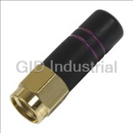
LINX TECHNOLOGIES ANT-315-SP

Description
ANTENNA 315MHZ PLANAR (SMT)
Part Number
ANT-315-SP
Price
Request Quote
Manufacturer
LINX TECHNOLOGIES
Lead Time
Request Quote
Category
PRODUCTS - A
Datasheet
Extracted Text
GROUND
GROUND
GROUND
GROUND
GROUND
ANT. FEED
DATA GUIDE
“SPLATCH” PLANAR
ANTENNAS
INTRODUCTION
0.062"
The “Splatch” is a breakthrough in compact antenna 433-SP
technology. It combines excellent performance and
1
GROUNDED LINE PLANAR ANTENNA
cost-effectiveness into an antenna package that can be
integrated, even by designers lacking RF test equipment.
Despite its simplicity and ease of use the “Splatch” should
1.102"
not be thought of as “just any other part”. Its correct function
is critical to the performance of your overall device.
Dropping the “Splatch” in the center of your board like any 433-SP
popcorn IC will likely yield dismal results. It is critical to
follow the guidelines below in order to obtain proper
GROUNDED LINE PLANAR ANTENNA
function. 1 1
0.200"
0.540"
FEATURES:
Physical Dimensions
■ Low Cost
■ Eliminates unsightly external antennas
■ Easily concealed
418-SP
■ Direct PCB mounting
GROUNDED LINE PLANAR ANTENNA
1
■ Reflow compatible
■ Stable grounded-line element
■ Excellent proximity performance
Electrical Connections
■ 10MHz approximate useable bandwidth
APPLICATIONS INCLUDE:
■ Remote control
■ Keyless entry
■ Garage / Gate openers
ORDERING INFORMATION
■ Lighting control
PART # DESCRIPTION
■ Medical monitoring
ANT-***-SP Splatch Planar Antenna
■ Remote data transfer
***= 315, 418, 433, 868, 916
Custom frequencies available with NRE.
■ Fire / Security systems
Splatch antennas are supplied in tube
■ RFID
packaging - 20 pcs. per tube.
Tape and reel available at extra cost on request.
■ Pagers
Revised 08/13/04
418
ATTACHMENT FEED CONSIDERATIONS
The antenna pads are designed to support both hand and automated Like most reduced-size antennas the “Splatch” has a fairly high Q and thus
placement. Castellations have been provided to ease solder introduction exhibits narrow bandwidth characteristics. The single most critical element in
during hand assembly. The parts are also fully compatible with the reflow insuring the optimum function of the “Splatch” is to minimize the length of the
process for automated assembly. feed trace (Transmission Line) to the “Splatch” itself. The feed trace should
be less than .25" and in all cases microstripped. The term “Microstrip” refers
to a trace passed over groundplane of a width appropriate to create a 50-ohm
transmission line between the module and the antenna. Since the antenna
APPLICATION CONSIDERATIONS
does not present a true and stable 50-ohm match, the feed trace tends to
When implemented correctly the “Splatch” will yield outstanding and repeat-
lower the antenna’s resonant frequency. Given the antenna’s narrow
able results. However, the “Splatch” was designed with very specific feed and
bandwidth, it can easily be detuned by the length of the feed trace; thus, the
mounting requirements. Failure by the designer to respect these require-
trace should be kept as short as possible. Additional microstrip details are
ments will result in unsatisfactory performance.
available in the reference section of this guide
* The antenna is tuned for direct mounting to a product’s PCB. Mounting the
antenna in any other manner will produce poor results. LAYOUT CONSIDERATIONS
* The antenna should be fed with a trace <=.25". Longer runs or coax feeds Improper placement of planes, traces or components will result in antenna nulls
are not recommended.
or complete detuning. First, the area under the antenna on all board layers
should be completely free of components, traces, or groundplane. In addition,
* Nothing should be placed under or directly beside the antenna element.
no components or traces should pass within .25" of the top, sides, front or back
Generally, mounting the antenna at the front of a product as illustrated will
of the antenna. Ideally the antenna will be mounted at the top of the board and
yield the best results.
given an unobstructed field of view in all directions. Components placed in the
area below the back edge of the antenna will have little effect since the antenna
has a null at its back edge when referenced appropriately to groundplane.
Components placed to the sides or top of the antenna or items such as
No
displays mounted in proximity to the antenna will produce nulls and, possibly,
Groundplane/Copper/Trace
detuning. The antenna may be referenced to groundplanes of all different
433-SP
Area - BARE PCB
surface areas; however, it has been optimized for a 1.5"x 3" plane area. The
.25" or Less
GROUNDED LINE PLANAR ANTENNA
1
best performance and lowest VSWR will be obtained when referenced to a
Microstripped
plane of similar area.
Vias To
Feedline
Groundplane
The recommended pad layout is illustrated below. The top layer of the board
generally has the antenna mounting pads and feed trace. The ground pads are
connected to the groundplane layer through vias. Use care in the sizing and
placement of the vias to prevent solder migration from the attachment pads
Groundplane on
during attachment.
Rear of Board
0.090"
Top Layer
Vias To
0.100"
Groundplane
Bottom Layer
Pads and outline shown
for groundplane
position reference only.
Typical Remote Control Application
Page 2 Page 3
SPLATCH SERIES PERFORMANCE DATA
About These Measurements
Splatch Under
The typical performance graphs below were based on a "Splatch" antenna 0.550"
Test
affixed to the test jig illustrated, and measured with a HP-8753D network ana-
lyzer in a 20°-25°C environment.
Vias To
*As of the time of this publication, full pattern characterization data was not avail-
Groundplane
able. Refer to the Linx website for periodic updates to this document.
8" of RG-174
Specification Frequency Units Notes
.062 FR4
Cable
Substrate
315 418 433.92 868 900 MHz
Electrical Length 1/4λ 1/4λ 1/4λ 1/4λ 1/4λ
3.000"
Center Frequency 315 418 433.92 868 916 MHz 1
Useable Bandwidth 10 10 10 20 40 MHz
Characteristic Impedence 50 50 50 50 50 Ohms 1, 2
1 oz. Copper
VSWR <1.7 Typ. <1.7 Typ. <1.7 Typ. <1.7 Typ. <1.7 Typ. 1
Groundplane
Gain/
Frequently asked questions
What makes Elite.Parts unique?

What kind of warranty will the ANT-315-SP have?

Which carriers does Elite.Parts work with?

Will Elite.Parts sell to me even though I live outside the USA?

I have a preferred payment method. Will Elite.Parts accept it?


 Manufacturers


What they say about us
FANTASTIC RESOURCE
One of our top priorities is maintaining our business with precision, and we are constantly looking for affiliates that can help us achieve our goal. With the aid of GID Industrial, our obsolete product management has never been more efficient. They have been a great resource to our company, and have quickly become a go-to supplier on our list!
Bucher Emhart Glass
EXCELLENT SERVICE
With our strict fundamentals and high expectations, we were surprised when we came across GID Industrial and their competitive pricing. When we approached them with our issue, they were incredibly confident in being able to provide us with a seamless solution at the best price for us. GID Industrial quickly understood our needs and provided us with excellent service, as well as fully tested product to ensure what we received would be the right fit for our company.
Fuji
HARD TO FIND A BETTER PROVIDER
Our company provides services to aid in the manufacture of technological products, such as semiconductors and flat panel displays, and often searching for distributors of obsolete product we require can waste time and money. Finding GID Industrial proved to be a great asset to our company, with cost effective solutions and superior knowledge on all of their materials, it’d be hard to find a better provider of obsolete or hard to find products.
Applied Materials
CONSISTENTLY DELIVERS QUALITY SOLUTIONS
Over the years, the equipment used in our company becomes discontinued, but they’re still of great use to us and our customers. Once these products are no longer available through the manufacturer, finding a reliable, quick supplier is a necessity, and luckily for us, GID Industrial has provided the most trustworthy, quality solutions to our obsolete component needs.
Nidec Vamco
TERRIFIC RESOURCE
This company has been a terrific help to us (I work for Trican Well Service) in sourcing the Micron Ram Memory we needed for our Siemens computers. Great service! And great pricing! I know when the product is shipping and when it will arrive, all the way through the ordering process.
Trican Well Service
GO TO SOURCE
When I can't find an obsolete part, I first call GID and they'll come up with my parts every time. Great customer service and follow up as well. Scott emails me from time to time to touch base and see if we're having trouble finding something.....which is often with our 25 yr old equipment.
ConAgra Foods