LG ELECTRONICS LM300W01

Description
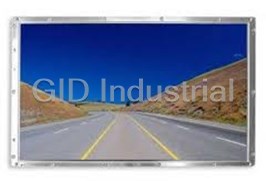
LG Electronics LM300W01 30” WQXGA TFT LCD
Part Number
LM300W01
Price
Request Quote
Manufacturer
LG ELECTRONICS
Lead Time
Request Quote
Category
PRODUCTS - L
Datasheet
Extracted Text
LM300W01
Liquid Crystal Display
Product Specification
SPECIFICATION
FOR
APPROVAL
( ) Preliminary Specification
(◆ ) Final Specification
Title 30” WQXGA TFT LCD
BUYER SUPPLIER LG.Philips LCD CO., Ltd.
MODEL *MODEL LM300W01
SUFFIX A3
*When you obtain standard approval,
please use the above model name without suffix
SIGNATURE DATE DATE
APPROVED BY
S.G.Hong / G.Manager
/
REVIEWED BY
P.Y.Kim / Manager
/
PREPARED BY
D.Y.Kim / Engineer
/
Please return 1 copy for your confirmation with Product Engineering Dept.
your signature and comments. LG. Philips LCD Co., Ltd
1/30
Ver. 1.0 JUL. 20, 2004
LM300W01
Liquid Crystal Display
Product Specification
CONTENTS
NO. ITEM Page
- COVER 1
- CONTENTS 2
- RECORD OF REVISIONS 3
1 GENERAL DESCRIPTION 4
2 ABSOLUTE MAXIMUM RATINGS 5
3 ELECTRICAL SPECIFICATIONS 6
3-1 ELECTRICAL CHARACTERISTICS 6
3-2 INTERFACE CONNECTIONS 8
3-3 SIGNAL TIMING SPECIFICATIONS 12
3-4 SIGNAL TIMING WAVE FORMS 14
3-5 COLOR INPUT DATA REFERANCE 15
3-6 POWER SEQUENCE 16
4 OPTICAL SPECIFICATIONS 18
5 MECHANICAL CHARACTERISTICS 23
6 RELIABILITY 26
7 INTERNATIONAL STANDARDS 27
7-1 SAFETY 27
7-2 EMC 27
8 PACKING 28
8-1 DESIGNATION OF LOT MARK 28
8-2 PACKING FORM 28
9 PRECAUTIONS 29
2/30
Ver. 1.0 JUL. 20, 2004
LM300W01
Liquid Crystal Display
Product Specification
RECORD OF REVISIONS
Revision No Data Page Description
Ver. 1.0 Jul. 20, 2004 Final Specifications
3/30
Ver. 1.0 JUL. 20, 2004
Gate D-IC(Right)
Gate D-IC(Right)
CN1 CN2 CN3
LM300W01
Liquid Crystal Display
Product Specification
1. General Description
The LM300W01 LCD is a Color Active Matrix Liquid Crystal Display with an integral Cold Cathode Fluorescent
Lamp(CCFL) back light system. The matrix employs a-Si Thin Film Transistor as the active element. It is a
transmissive type display operating in the normally black mode. This TFT-LCD has a 30.0 inch diagonally
measured active display area with WQXGA resolution(2560 vertical by 1600 horizontal pixel array). Each pixel
is divided into Red, Green and Blue sub-pixels or dots which are arranged in vertical stripes. Gray scale or the
luminance of the sub-pixel color is determined with a 8-bit gray scale signal for each dot, thus, presenting a
palette of more than 16,777,216 colors.
TM
The LM300W01 has been designed to apply the Dual TMDS (Transition Minimized differential Signaling) as
the interface method to enables a simple and low-cost implementation in both the host and monitor.
Mini LVDS Signal(Right)
Dual Link TMDS Rx
Mini LVDS Signal(Left)
Control Signal
DCLK
RX0~2,C TMDS
(Source/Gate)
Receiver
H,V,DE
(Master)
QE
TCON
RX3~5 Source D-IC(Left) Source D-IC(Right)
TMDS QO
1 2560
Receiver
DSEL
11
(Slave)
Signal Spread
Vcc Vcc
30” TFT-LCD Panel
Spectrum
PWR ON
Power Block
( 2560 x 1600 )
(V ,V ,V , V ,V ,V ,
CC DD GH CC DD GH
V (18V)
LCD
V ,Gamma,V )
V ,Gamma,V
GL COM
GL COM
1600
1600
2pin x 8CNs (High)
+24.0V
Back light Assembly (16CCFL)
Inverter
2pin x 1CNs (Low)
Figure 1. Block diagram
General Features
Active screen size 30.0 inches (756.228mm) diagonal
Outline Dimension 677.30(H) x 436.80(V) x 42.30(D) mm(Typ.)
Pixel Pitch 0.2505 mm x 0.2505 mm
Pixel Format 2560 horizontal By 1600 vertical Pixels. RGB stripe arrangement
Color Depth 8-bit, 16,777,216 color
2
Luminance, White 280 cd/m ( 5 points Avg.)
Viewing Angle(CR>10) Viewing Angle Free(R/L 176(Typ.), U/D 176(Typ.))
Power Consumption Total 106.5 Watt(Typ.), (11.5 Watt @V , 95 Watt @280cd/[Lamp=5mA])
LCD
Weight 5,100 g (Typ.)
Display Operating Mode Transmissive mode, normally Black
Surface Treatments Hard coating (3H), Anti-glare treatment of the front polarizer
4/30
Ver. 1.0 JUL. 20, 2004
LM300W01
Liquid Crystal Display
Product Specification
2. Absolute Maximum Ratings
The following are maximum values which, if exceeded, may cause faulty operation or damage to the unit.
Table 1. Absolute Maximum Ratings
Values
Parameter Symbol Units Notes
Min. Max.
Power Supply Input Voltage for Panel V -0.3 21.0 V At 25℃ ± 2°C
LCD dc
T
Operating Temperature 0 50 1
OP ℃
Storage Temperature T -20 60
℃
ST
Operating Ambient Humidity
H 10 90 %RH
OP
Storage Humidity H
10 90 %RH
ST
Note : 1. Temperature and relative humidity range are shown in the figure below.
Wet bulb temperature should be 39 °C Max, and no condensation of water.
90%
60
60%
50 Storage
Wet Bulb
Temperature [C]
40
40%
Operation
30
20
10
0
10%
-20 0 10 20 30 40 50 60 70 80
Dry Bulb Temperature [C]
Figure 2. Temperature and relative humidity
5/30
Ver. 1.0 JUL. 20, 2004
Humidity [(%)RH]
LM300W01
Liquid Crystal Display
Product Specification
3. Electrical Specifications
3-1. Electrical Characteristics
It requires two power inputs. One is employed to power the LCD electronics and to drive the TFT array and
liquid crystal. The second input power for the CCFL, is typically generated by an inverter. The inverter is an
external unit to the LCDs.
Table 2. Electrical Characteristics
Values
Parameter Symbol Unit Notes
Min Typ Max
MODULE :
Power Supply Input Voltage VLCD 17.0 18.0 19.0 Vdc
Permissive Power Input Ripple VdRF 400 mVp-p
540 640 740 1
㎃
Power Supply Input Current ILCD
- 810 1040 2
㎃
Power Consumption PLCD - 11.5 13.3 Watt 1
Rush current IRUSH -- 4 A 3
Note :
1. The specified current and power consumption are under the V =18.0V, 25 ± 2°C,f =60Hz condition
LCD V
whereas mosaic pattern(8 x 6) is displayed and f is the frame frequency.
V
2. The current is specified at the maximum current pattern.
3. The duration of rush current is about 2ms and rising time of power Input is 1ms(min.).
White : 255Gray Maximum current pattern
Black : 0Gray
Mosaic Pattern(8 x 6) White Pattern
[ Figure 3 ] Mosaic pattern : for power consumption measurement
6/30
Ver. 1.0 JUL. 20, 2004
LM300W01
Liquid Crystal Display
Product Specification
Table 3. INVERTER Electrical Characteristics
Values
Parameter Symbol Condition Unit Notes
Min. Typ. Max.
Inverter :
Input Voltage V 21.6 24.0 26.4 V 1
BL
Input Current I V = 3.3V 3.65 4.2 A 2
BL BR
Input Power PBL V = 3.3V 88.0 100 Watt 2
BR
B/L on/off control VON/OFF Lamp ON = High 2.0 - 5.0 V
Lamp OFF =Low 0.0 - 0.8 V
Brightness Adj VBR 0- 3.3 V
LAMP :
Life time 50,000 Hrs 3
Notes :
1. The input voltage ripple is limited below 400mVp-p.
2.The specified current and power consumption are under the typical supply Input voltage, 24V.
3.The life is determined as the time at which luminance of the lamp is 50% compared to that of initial
value at the typical lamp current on condition of continuous operating at 25 ± 2°C.
4. Electrical characteristics are determined after the unit has been ‘ON’ and stable for approximately
30min in a dark environment at 25 °C± 2°C.
7/30
Ver. 1.0 JUL. 20, 2004
LM300W01
Liquid Crystal Display
Product Specification
3-2. Interface Connections
This LCD employs three kinds of interface connections. A 30-pin connector is used for TMDS signals from
the host computer. A 15-pin connector is used for LCD module power and LCM controls signal from external
monitor control circuits. And 14-pin connector is used for the inverter for backlight system.
3-2-1. Signal Interface
The Dual TMDS signal interface connector is FI-XL30SSL-HF(manufactured by JAE) or equivalent.
The pin configuration for the 30 pin connector is shown in the table below.
Table 4. 30Pin Connector pin configuration(For Dual Link TMDS)
Pin No. Symbol Description Pin No. Symbol Description
TMDS negative differential
1 GND NC 16 RxC-
output(Channel C)
2 GND NC 17 SHLD5 Shield for TMDS Channel 5
TMDS positive differential
3 GND NC 18 Rx5+
output(Channel 5)
TMDS negative differential
4 GND NC 19 Rx5-
output(Channel 5)
5 SHLD2 Shield for TMDS Channel 2 20 SHLD4 Shield for TMDS Channel 4
TMDS positive differential TMDS positive differential
6 Rx2+ 21 Rx4+
output(Channel 2) output(Channel 4)
TMDS negative differential TMDS negative differential
7 Rx2- 22 Rx4-
output(Channel 2) output(Channel 4)
8 SHLD1 Shield for TMDS Channel 1 23 SHLD3 Shield for TMDS Channel 3
TMDS positive differential TMDS positive differential
9 Rx1+ 24 Rx3+
output(Channel 1) output(Channel 3)
TMDS negative differential TMDS negative differential
10 Rx1- 25 Rx3-
output(Channel 1) output(Channel 3)
11 SHLD0 Shield for TMDS Channel 0 26 GND NC
TMDS positive differential
12 Rx0+ 27 GND NC
output(Channel 0)
TMDS negative differential
13 Rx0- 28 GND NC
output(Channel 0)
14 SHLDC Shield for TMDS Channel C 29 GND NC
TMDS positive differential
15 RxC+ 30 GND NC
output(Channel C)
Notes : 1. Interface Chips
: SiI163B x 2ea (Dual TMDS Receiver ,Silicon Image)
2. Connector
2.1 Connector(Receptacle) : FI-X30SSL-HF(JAE) or Equivalent.
2.2 Mating Connector(Plug) : FI-X30H and FI-X30HL or its equivalent.
8/30
Ver. 1.0 JUL. 20, 2004
LM300W01
Liquid Crystal Display
Product Specification
3-2-2.Power Connector
The power connector is 53261 (manufactured by Molex) or equivalent.
The pin configuration for the 15 pin connector is shown in the table below.
Table 5. 15Pin Connector pin configuration (Power Connector CN1)
Pin Symbol Description Notes
1 GND Ground
2 Save_Control Open Reserved
3 PWR_ON LCM ON control signal input
4 GND Ground
5 V LCM power supply, +18V ±5%
LCD
6 V LCM power supply, +18V ±5%
LCD
7 V LCM power supply, +18V ±5%
LCD
8 V LCM power supply, +18V ±5%
LCD
9 GND Ground
10 NC Open Reserved
11 NC Open Reserved
12 GND Ground
Reserved(AGP)
13 HS_OUT Hsync Output
14 VS_OUT Vsync Output
High3.3V) :Dual
15 PS_ON Dual / Single mode Output
Low(0V) :Single
Notes : 1. Connector
1) Connector(Receptacle) : 53261 (Molex) of Equivalent.
2) Mating Connector(Plug) : 51021 or its equivalent.
9/30
Ver. 1.0 JUL. 20, 2004
LM300W01
Liquid Crystal Display
Product Specification
[ Figure 4 ] Connector diagram
#1 #15
#1 #30
FI-X30SSL-HF
53261
#15
#1
#1 #30
Rear view of LCM
Signal Connector(30pins) is left side and
Power Connector(15pins) is right side
Notes:
1. All GND(ground) pins should be connected together and should also be connected to the LCD’s metal
frame.
2. All power input pins should be connected together.
3. All NC pins should be separated from other signal or power.
10 /30
Ver. 1.0 JUL. 20, 2004
…
…
LM300W01
Liquid Crystal Display
Product Specification
3-2-3. Inverter Connector for Backlight
The inverter connector is S14B-PH-SM3(manufactured by JST) or equivalent
The pin configuration for the 14 pin connector is shown in the table below.
Table 6. 14Pin Connector Pin Configuration (Inverter Connector)
Pin Symbol Description Notes
1 V Power Supply, +24V
BL
2 V Power Supply, +24V
BL
3 V Power Supply, +24V
BL
4 V Power Supply, +24V
BL
5 V Power Supply, +24V
BL
6 GND Power Ground
7 GND Power Ground
8 GND Power Ground
9 GND Power Ground
10 GND Power Ground
11 VS No connection
ON : 2.0V~5.0V
12 V BL On/Off Control signal
ON
OFF : 0.0~0.8V
Max3.3V/Min0.0V
13 V PWM Dimming Control Signal
BR
Normal =0~0.8V
14 Status Lamp Operating Status
Abnormal=3.0~5.0V
1. Connector
PCB
1) Connector(Receptacle) : S14B-PH-SM3 (JST) or equivalent
2) Mating Connector(Plug) : PHR14 or its equivalent
14
1
Rear view of LCM
11 /30
Ver. 1.0 JUL. 20, 2004
LM300W01
Liquid Crystal Display
Product Specification
3-3. Signal Timing Specifications
This is the signal timing required at the input of the TMDS Transmitter. All of the interface signal timing should
be satisfied with the following specifications for it’s proper operation.
Table 7. TIMING TABLE_1 ( Dual mode: 2560x1600)
Dual mode: 2560x1600
PS_ON : High
ITEM SYMBOL Min Typ Max Unit Note
t ns
Period CLK 7.45 7.45 7.45
DCLK
268.5 / 2
f MHz
Frequency CLK 134.25 134.25 134.25
(Dual)
Width-Total tHT 2720 2720 2720 tCLK
Period tHP - 10.13 - us
Hsync
Frequency f - 98.71 - KHz
H
Width tWH - 32 - tCLK
t t
Width-Total VT 1646 1646 1646 HP
t
Period VP - 16.68 -
Vsync
Frequency f - 59.97 - Hz
V
Width t - 6 - t
WV HP
Horizontal Valid t
HV 2560 2560 2560
t
Horizontal Back Porch HBP - 80 -
t
CLK
Horizontal Front Porch t - 48 -
HFP
Horizontal Blank - - 160 - t + t + t
WH HBP HFP
Data
Enable
t
Vertical Valid V V 1600 1600 1600
t
Vertical Back Porch VBP - 38 -
t
HP
t
Vertical Front Porch VFP - 2 -
Vertical Blank - - 46 - t + tV + t
WV BP VFP
Note: Hsync period and Hsync width-active should be even number times of tCLK. If the value is odd number
times of tCLK, display control signal can be asynchronous. In order to operate this LCM a Hsync,
Vsyn, and DE(data enable) signals should be used.
1. : The performance of the electro-optical characteristics may be influenced by variance of the vertical
refresh rates.
2. Vsync and Hsync should be keep the above specification.
3. Hsync Period, Hsync Width, and Horizontal Back Porch should be any times of of character
number(8).
4. The polarity of Hsync, Vsync is not restricted.
12 /30
Ver. 1.0 JUL. 20, 2004
LM300W01
Liquid Crystal Display
Product Specification
Table 8. TIMING TABLE_2 ( Single mode: 1280x800)
Single mode: 1280x800
PS_ON : Low
ITEM SYMBOL Min Typ Max Unit Note
Period t 14.08 14.08 14.08 ns
CLK
DCLK
f MHz Single
Frequency CLK 71.00 71.00 71.00
Width-Total t 1440 1440 1440 t
HP CLK
Period t - 20.28 - us
HP
Hsync
f KHz
Frequency H - 49.31 -
Width t - 32 - t
WH CLK
Width-Total tVT 823 823 823 tHP
t ms
Period VP - 16.69 -
Vsync
Frequency f - 59.91 - Hz
V
t t
Width WV - 6 - HP
Horizontal Valid t 1280 1280 1280
HV
t
Horizontal Back Porch HBP - 80 -
t
CLK
Horizontal Front Porch t - 48 -
HFP
- t + t + t
Horizontal Blank - 160 - WH HBP HFP
Data
Enable
Vertical Valid t 800 800 800
V V
t
Vertical Back Porch VBP - 15 -
t
HP
t
Vertical Front Porch VFP - 2 -
Vertical Blank - - 23 - tWV+ tVBP+ tVFP
Notes :
Hsync period and Hsync width-active should be even number times of tCLK. If the value is odd number
times of tCLK, display control signal can be asynchronous. In order to operate this LCM a Hsync.,Vsync
and DE(data enable) signals should be used.
1. The performance of the electro-optical characteristics are may be influenced by variance of the
vertical refresh rates.
2. Vsync, Hsync should be keep the above specification.
3. Hsync Period should be a double number of character (8).
4. The polarity of Hsync, Vsync is not restricted.
13 /30
Ver. 1.0 JUL. 20, 2004
LM300W01
Liquid Crystal Display
Product Specification
3-4. Signal Timing Waveforms
0.7Vcc
Hsync, Vsync, DE, Data
0.3Vcc
tCLK
0.5 Vcc
DCLK
Valid data
Invalid data Invalid data
DE(Data Enable)
tHP
HSync
tWH
tHBP tHV tHFP
DE(Data Enable)
tVP
tWV
VSync
tVBP tVV tVFP
DE(Data Enable)
14 /30
Ver. 1.0 JUL. 20, 2004
LM300W01
Liquid Crystal Display
Product Specification
3-5. Color Input Data Reference
The brightness of each primary color (red,green and blue) is based on the 8-bit gray scale data input for the
color ; the higher the binary input, the brighter the color. The table below provides a reference for color
versus data input.
Table 9. COLOR DATA REFERENCE
Input Color Data
Red Green Blue
Color
MSB LSB MSB LSB MSB LSB
R7 R6 R5 R4 R3 R2 R1 R0 G7G6G5G4G3G2G1G0 B7 B6 B5 B4 B3 B2 B1 B0
Black 0 0 0 0 0 0 0 0 0 0 0 0 0 0 0 0 0 0 0 0 0 0 0 0
Red (255)
1 1 1 1 1 1 1 1 0 0 0 0 0 0 0 0 0 0 0 0 0 0 0 0
Green (255)
0 0 0 0 0 0 0 0 1 1 1 1 1 1 1 1 0 0 0 0 0 0 0 0
Blue (255)
Basic 0 0 0 0 0 0 0 0 0 0 0 0 0 0 0 0 1 1 1 1 1 1 1 1
Color Cyan 0 0 0 0 0 0 0 0 1 1 1 1 1 1 1 1 1 1 1 1 1 1 1 1
Magenta
1 1 1 1 1 1 1 1 0 0 0 0 0 0 0 0 1 1 1 1 1 1 1 1
Yellow
1 1 1 1 1 1 1 1 1 1 1 1 1 1 1 1 0 0 0 0 0 0 0 0
White
1 1 1 1 1 1 1 1 1 1 1 1 1 1 1 1 1 1 1 1 1 1 1 1
Red(000) Dark 0 0 0 0 0 0 0 0 0 0 0 0 0 0 0 0 0 0 0 0 0 0 0 0
Red(001)
0 0 0 0 0 0 0 1 0 0 0 0 0 0 0 0 0 0 0 0 0 0 0 0
Red(002)
0 0 0 0 0 0 1 0 0 0 0 0 0 0 0 0 0 0 0 0 0 0 0 0
---- -----
- - - - - - - - - - - - - - - - - - - - - - - -
Red
---- ----- - - - - - - - - - - - - - - - - - - - - - - - -
Red(253)
1 1 1 1 1 1 0 1 0 0 0 0 0 0 0 0 0 0 0 0 0 0 0 0
Red(254)
1 1 1 1 1 1 1 0 0 0 0 0 0 0 0 0 0 0 0 0 0 0 0 0
Red(255) Bright
1 1 1 1 1 1 1 1 0 0 0 0 0 0 0 0 0 0 0 0 0 0 0 0
Green(000) Dark 0 0 0 0 0 0 0 0 0 0 0 0 0 0 0 0 0 0 0 0 0 0 0 0
Green(001)
0 0 0 0 0 0 0 0 0 0 0 0 0 0 0 1 0 0 0 0 0 0 0 0
Green(002)
0 0 0 0 0 0 0 0 0 0 0 0 0 0 1 0 0 0 0 0 0 0 0 0
---- -----
- - - - - - - - - - - - - - - - - - - - - - - -
Green
---- ----- - - - - - - - - - - - - - - - - - - - - - - - -
Green(253)
0 0 0 0 0 0 0 0 1 1 1 1 1 1 0 1 0 0 0 0 0 0 0 0
Green(254)
0 0 0 0 0 0 0 0 1 1 1 1 1 1 1 0 0 0 0 0 0 0 0 0
Green(255) Bright
0 0 0 0 0 0 0 0 1 1 1 1 1 1 1 1 0 0 0 0 0 0 0 0
Blue(000) Dark 0 0 0 0 0 0 0 0 0 0 0 0 0 0 0 0 0 0 0 0 0 0 0 0
Blue(001)
0 0 0 0 0 0 0 0 0 0 0 0 0 0 0 0 0 0 0 0 0 0 0 1
Blue(002)
0 0 0 0 0 0 0 0 0 0 0 0 0 0 0 0 0 0 0 0 0 0 1 0
---- -----
- - - - - - - - - - - - - - - - - - - - - - - -
Blue
---- ----- - - - - - - - - - - - - - - - - - - - - - - - -
Blue(253)
0 0 0 0 0 0 0 0 0 0 0 0 0 0 0 0 1 1 1 1 1 1 0 1
Blue(254)
0 0 0 0 0 0 0 0 0 0 0 0 0 0 0 0 1 1 1 1 1 1 1 0
Blue(255) Bright
0 0 0 0 0 0 0 0 0 0 0 0 0 0 0 0 1 1 1 1 1 1 1 1
15 /30
Ver. 1.0 JUL. 20, 2004
LM300W01
Liquid Crystal Display
Product Specification
3-6. Power Sequence for Panel
V
LCD
90% 90%
10% Customers can monitor H , ,V with V on. 10%
sync sync LCD
Power Supply, V 0V
LCD
T1 T9
T8
Interface Signal, V
i
T2
(Digital RGB signal, Invalid Period
Valid Period Valid Period
( Monitoring H ,
SCDT ,V , H , DE, sync
sync sync
,V )
sync
Clock to PanelLink
Transmitter)
T6
T6 T3
T3
3.3V
90%
PWR_CTRL signal
10%
for LCM power down
0V
T7
T5
T4
T4 T5
Power Supply for Backlight LAMP ON
LAMP OFF LAMP OFF
Inverter
Table 10. Power Sequence
Values
Parameter Units Notes
Min. Typ. Max.
T1 - 30 ms
T2
- - - ms
T3
300
- ms
T4
-
100 ms
T5 80
- ms
T6 80
- ms
-
T7 400 ms
-
T8 50 ms
10
T9 - ms
Notes : 1. Please avoid floating state of interface signal at invalid period.
2. When the interface signal is invalid, be sure to pull down the power supply for LCD V to 0V.
LCD
3. Lamp power must be turn on after power supply for LCD and interface signal are valid.
16 /30
Ver. 1.0 JUL. 20, 2004
LM300W01
Liquid Crystal Display
Product Specification
3-6. Power Sequence for Inverter
V
BL
90%
Power Supply_V
BL
10%
0V
T1
T2 T4
Lamp ON/OFF
LAMP ON
LAMP OFF
T3
Lamp Dimmer
T5
Vin_typ
Vin_dip≤ Vin_typ × 0.2
Vin Dipping
0V
Table 11. Power Sequence
Values
Parameter Units Notes
Min. Typ. Max.
T1 1 - 30 ms
T2
200 - - ms
T3
- 50
- ms
T4
- -
500 ms
T5
- 10
- ms
17 /30
Ver. 1.0 JUL. 20, 2004
LM300W01
Liquid Crystal Display
Product Specification
4. Optical Specification
Optical characteristics are determined after the unit has been ‘ON’ and stable for approximately 30 minutes in
a dark environment at 25 °C. The values specified are measured at an approximate distance 50cm from the
LCD surface at a viewing angle of Φ and θ equal to 0 °.
Figure. 5 presents additional information concerning the measurement equipment and method.
LCD Module Pritchard 880 or
Optical Stage(x,y)
equivalent
50cm
[Figure 5] Optical characteristic measurement equipment and method
Table 12. Optical characteristics (Ta=25±2°C, V =18V, f =60Hz, CLK=134.25MHz, I =5mA)
LCD V OUT
Values
Parameter Symbol Units Notes
Min Typ Max
Contrast Ratio CR 300 400 1
2
Surface Luminance, white L 220 280 cd/m 2
WH
Luminance Variation δ 30 35 % 3
WHITE
Rise Time Tr - 9 15 ms 4
R
Decay Time Tr - 7 15 ms 4
D
Response Time
T - 12 - ms 5
GTG_AVR
Gray To Gray
T - 18 - ms 5
GTG_MAX
RED Rx 0.640
Ry 0.343
GREEN Gx 0.292
Gy 0.611
Typ Typ
Color Coordinates
[CIE1931]
-0.03 +0.03
BLUE Bx 0.146
By 0.074
WHITE Wx 0.313
Wy 0.331
Horizontal θ - 176 - degree 6
CST_H
Color shift
Vertical θ - 176 -
CST_V
Viewing Angle (CR>10)
Horizontal 170 176 -
θ
H
general degree 7
Vertical 170 176 -
θ
V
Horizontal - 176 -
θ
GMA_H
Effective degree 8
Vertical - 176 -
θ
GMA_V
Gray Scale 2.2 9
18 /30
Ver. 1.0 JUL. 20, 2004
LM300W01
Liquid Crystal Display
Product Specification
Notes 1. Contrast Ratio(CR) is defined mathematically as :
Surface Luminance with all white pixels
Contrast Ratio =
Surface Luminance with all black pixels
2. Surface luminance is luminance value at 5 points average across the LCD surface 50cm
from the surface with all pixels displaying white. For more information see FIG 2.
L = = Average[ L 1,L 2,L 3,L 4,L 5]
WH on on on on on
3. The variation in surface luminance , δ WHITE is defined as :
Maximum(L ,L , ….. L ) - Minimum(L ,L , ….. L )
on1 on2 on13 on1 on2 on13
δ = ×100(%)
WHITE
Average (L , L , .... L )
on1 on2 on5
Measuring point for surface luminance & measuring point for luminance variation
H
A
H/16
67 8
2 3
B
V
10
9 1
4
5
13
11 12
V/10
Active Area
A : H/4 mm
B : V/4 mm
@ H,V : Active Area
FIG. 2 Measure Point for Luminance
19 /30
Ver. 1.0 JUL. 20, 2004
LM300W01
Liquid Crystal Display
Product Specification
4. The response time is defined as the following figure and shall be measured by switching
the input signal for “black” and “white”.
Response time is the time required for the display to transition from black to white (Rise Time,
TrR) and from white to black (Decay Time, TrD).
TrR
TrD
100
90
Optical
Response
10
0
white
black
black
FIG. 3 Response Time
5. The Gray to Gray response time is defined as the following figure and shall be measured
by switching the input signal for “Gray To Gray “.
- Gray step : 5 Step
-T is the total average time at rising time and falling time for “Gray To Gray “.
GTG_AVR
-T is the max time at rising time or falling time for “Gray To Gray “.
GTG_MAX
Rising Time
Gray to Gray
G255 G191 G127 G63 G0
Falling Time G255
G191
G127
G63
G0
20 /30
Ver. 1.0 JUL. 20, 2004
LM300W01
Liquid Crystal Display
Product Specification
6. Color shift is the angle at which the color difference is lower than 0.04.
- Color difference(Δu’v’)
9y
4x
v’=
u’=
-2x + 12y +3
-2x + 12y + 3
u’1, v’1 : u’v’ value at viewing angle direction
2 2
Δu’v’ = (u’ -u’ ) +(v’ -v’ )
u’2, v’2 : u’v’ value at front(θ=0)
1 2 1 2
- Pattern size : 25% Box size
- Viewing angle direction of color shift : Horizontal, Vertical
θ = 0。
φ = 90。 z A
yu
(12:00)
θ 25% Box size
φ
φ = 180。 φ = 0。
xl
(9:00) (3:00) xr
TFT LCD φ = 270。
z' yd
MODULE (6:00)
Viewing angle direction
Average RGB values in Bruce RGB for Macbeth Chart
Dark skin Light skin Blue sky Foliage Blue flower Bluish green
R 98 206 85 77 129 114
G 56 142 112 102 118 199
B 45 123 161 46 185 178
Orange Purplish blue Moderate red Purple Yellow green Orange yellow
R 219 56 211 76 160 230
G 104 69 67 39 193 162
B 24 174 87 86 58 29
Blue Green Red Yellow Magenta cyan
R 26 72 197 241 207 35
G 32 148 27 212 62 126
B 145 65 37 36 151 172
White Neutral 8 Neutral 6.5 Neutral 5 Neutral 3.5 black
R 240 206 155 110 63 22
G 240 206 155 110 63 22
B 240 206 155 110 63 22
21 /30
Ver. 1.0 JUL. 20, 2004
LM300W01
Liquid Crystal Display
Product Specification
7. Viewing angle(general) is the angle at which the contrast ratio is greater than 10.
8. Effective viewing angle is the angle at which the gamma shift of gray scale is lower than 0.3.
r
log(L −L ) =r log(V ) + log(a)
L =aV +L
b
b
Here the Parameter α and γ relate the signal level V to the luminance L.
The GAMMA we calculate from the log-log representation (Fig. 2)
9. Gray scale specification
Gamma Value is approximately 2.2. For more information see Table 8.
Table 8. Gray Scale Specification
Gray Level Relative Luminance [%] (Typ.)
00.3
31 1.2
63 4.68
95 11.7
127 21.2
159 35.2
191 53.0
223 75.4
255 100
10. TCO ’03 item regarding Display characteristic is satisfied.
22 /30
Ver. 1.0 JUL. 20, 2004
LM300W01
Liquid Crystal Display
Product Specification
5. Mechanical Characteristics
The contents provide general mechanical characteristics. In addition the figures in the next page are detailed
mechanical drawing of the LCD.
Table 14. Mechanical characteristics
Horizontal 677.30 mm
Outline Dimension Vertical 436.80 mm
Depth 42.30 mm
Horizontal 646.30 mm
Bezel Area
Vertical 405.80 mm
Horizontal 641.28 mm
Active Display Area
Vertical 400.8 mm
Weight 5100g (Typ.), 5400g (Max.)
Hard coating(3H)
Surface Treatment
Anti-glare(13%) treatment of the front polarizer
Notes : Please refer to a mechanic drawing in terms of tolerance at the next page.
23 /30
Ver. 1.0 JUL. 20, 2004
LM300W01
Liquid Crystal Display
Product Specification
Frequently asked questions
What makes Elite.Parts unique?

What kind of warranty will the LM300W01 have?

Which carriers does Elite.Parts work with?

Will Elite.Parts sell to me even though I live outside the USA?

I have a preferred payment method. Will Elite.Parts accept it?


 Manufacturers




What they say about us
FANTASTIC RESOURCE
One of our top priorities is maintaining our business with precision, and we are constantly looking for affiliates that can help us achieve our goal. With the aid of GID Industrial, our obsolete product management has never been more efficient. They have been a great resource to our company, and have quickly become a go-to supplier on our list!
Bucher Emhart Glass
EXCELLENT SERVICE
With our strict fundamentals and high expectations, we were surprised when we came across GID Industrial and their competitive pricing. When we approached them with our issue, they were incredibly confident in being able to provide us with a seamless solution at the best price for us. GID Industrial quickly understood our needs and provided us with excellent service, as well as fully tested product to ensure what we received would be the right fit for our company.
Fuji
HARD TO FIND A BETTER PROVIDER
Our company provides services to aid in the manufacture of technological products, such as semiconductors and flat panel displays, and often searching for distributors of obsolete product we require can waste time and money. Finding GID Industrial proved to be a great asset to our company, with cost effective solutions and superior knowledge on all of their materials, it’d be hard to find a better provider of obsolete or hard to find products.
Applied Materials
CONSISTENTLY DELIVERS QUALITY SOLUTIONS
Over the years, the equipment used in our company becomes discontinued, but they’re still of great use to us and our customers. Once these products are no longer available through the manufacturer, finding a reliable, quick supplier is a necessity, and luckily for us, GID Industrial has provided the most trustworthy, quality solutions to our obsolete component needs.
Nidec Vamco
TERRIFIC RESOURCE
This company has been a terrific help to us (I work for Trican Well Service) in sourcing the Micron Ram Memory we needed for our Siemens computers. Great service! And great pricing! I know when the product is shipping and when it will arrive, all the way through the ordering process.
Trican Well Service
GO TO SOURCE
When I can't find an obsolete part, I first call GID and they'll come up with my parts every time. Great customer service and follow up as well. Scott emails me from time to time to touch base and see if we're having trouble finding something.....which is often with our 25 yr old equipment.
ConAgra Foods