

 Manufacturers
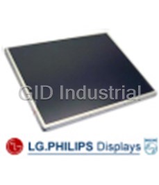
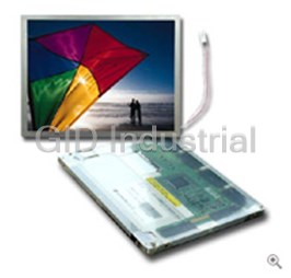
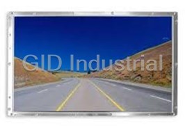
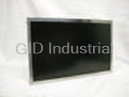
LG ELECTRONICS LM151X05

Description
LG Electronics LM151X05 LCD Screen - 15.1“ XGA TFT LCD
Part Number
LM151X05
Price
Request Quote
Manufacturer
LG ELECTRONICS
Lead Time
Request Quote
Category
PRODUCTS - L
Specifications
Active screen size
15.1 inches (307.2 x 230.4 mm) diagonal
Color depth
6-bit, 262,144 color
Display operating mode
Transmissive mode, normally white
Luminance, white
200 cd/m2 (Typ.)
Outline Dimension
352.0 (H) x 263.5 (V) x 14.0 (D) mm (Typ.) without user connector
Pixel format
1024 horiz. By 768 vert. Pixels RGB stripes arrangement
Pixel Pitch
0.300 mm x 0.300 mm
Power Consumption
1.6 Watts Logic / 8.6 Watts CCFL (Typ. With chess 8x6 pattern)
Surface treatments
Hard coating(3H)
Weight
1150g (Typ.)
Datasheet

Extracted Text
SPECIFICATIONS
LM151X05-A3C1 Rev. 1 Page 1 of 24
LM151X05 Liquid Crystal Display
LM151X05-A3C1
15.1“ XGA TFT LCD
PRELIMINARY
SPECIFICATION
The information given in this document is carefully checked and believed to be reliable. Data Display reserves
the right to make changes in product or specification at any time and without further notice. Data Display products
are not intended for use in systems in which failures of product could result in personal injury. All mentioned
trademarks are registered trademarks of their owner. LG.Philips LCD: Rev. 0.0 May 14, 2001
Vox Technologies Corporation - 1180 Commerce Drive, Richardson, Texas 75081 - www.voxtechnologies.com
Telephone: +1-972-234-4343 - Fax: +1-972-234-4295 - Email: info@voxtechnologies.com
SPECIFICATIONS
LM151X05-A3C1 Rev. 1 Page 2 of 24
LM151X05 Liquid Crystal Display
NO. ITEM Page
-
1
COVER
-
CONTENTS
2
-
3
RECORD OF REVISIONS
1 GENERAL DESCRIPTION 4
2 ABSOLUTE MAXIMUM RATINGS 5
ELECTRICAL SPECIFICATIONS
3 6
3-1 ELECTRICAL CHARACTREISTICS 7
3-2 INTERFACE CONNECTIONS 8
3-3 SIGNAL TIMING SPECIFICATIONS 9
3-4 SIGNAL TIMING WAVEFORMS 10
3-5
COLOR INPUT DATA REFERNECE 11
3-6 POWER SEQUENCE 12
4 14
OPTICAL SPECIFICATIONS
5 17
MECHANICAL CHARACTERISTICS
6 21
RELIABILITY
7
INTERNATIONAL STANDARDS 22
7-1
22
SAFETY
7-2 22
EMC
8 23
PACKING
8-1 23
DESIGNATION OF LOT MARK
8-2 PAKING FORM 23
9 24
PRECAUTIONS
Vox Technologies Corporation - 1180 Commerce Drive, Richardson, Texas 75081 - www.voxtechnologies.com
Telephone: +1-972-234-4343 - Fax: +1-972-234-4295 - Email: info@voxtechnologies.com
SPECIFICATIONS
LM151X05-A3C1 Rev. 1 Page 3 of 24
LM151X05 Liquid Crystal Display
RECORDS OF REVISIONS
Revision No Revision No Page DESCRIPTION
Ver 0.0 Mar. 02, 2001 - First Draft, Preliminary Specification
Vox Technologies Corporation - 1180 Commerce Drive, Richardson, Texas 75081 - www.voxtechnologies.com
Telephone: +1-972-234-4343 - Fax: +1-972-234-4295 - Email: info@voxtechnologies.com
Gate Driver circuit
SPECIFICATIONS
LM151X05-A3C1 Rev. 1 Page 4 of 24
LM151X05 Liquid Crystal Display
1. General Description
The LM151X05 is a Color Active Matrix Liquid Crystal Display with an integral Cold Cathode Fluorescent
Lamp(CCFL) backlight system. The matrix employs a-Si Thin Film Transistor as the active element.
It is a transmissive type display operating in the normally white mode. This TFT-LCD has 15.1 inches
diagonally measured active display area with XGA resolution(768 vertical by 1024 horizontal pixel array)
Each pixel is divided into Red, Green and Blue sub-pixels or dots which are arranged in vertical stripes.
Gray scale or the brightness of the sub-pixel color is determined with a 6-bit gray scale signal for each dot,
thus, presenting a palette of more than 262,144 colors.
The LM151X05 has been designed to apply the TTL interface method.
The LM151X05 LCD is intended to support applications where high response time, wide viewing angle,
high color saturation, and high color depth are very important.
In combination with the vertical arrangement of the sub-pixels, the LM151X05 characteristics provide an
excellent flat panel display for automation products such as monitors, Kiosk Terminals or Point of Information
Terminals.
G1
RGB data
(18bits)
TFT-LCD Panel
Timing Control
CN1
(1024 * 768 pixels)
Block
(41pin)
Dclk, DE
G768
V (+3.3V)
CC
Power Circuit Block
S1 S1024
Source Driver Circuit
V
Lamp
CN2
Backlight Assembly(2 CCFL)
V
Lamp CN3
General Features
Active screen size 15.1 inches (307.2 x 230.4 mm) diagonal
Outline Dimension 352.0 (H) x 263.5 (V) x 14.0 (D) mm (Typ.) without user connector
Pixel Pitch 0.300 mm x 0.300 mm
Pixel format 1024 horiz. By 768 vert. Pixels RGB stripes arrangement
Color depth 6-bit, 262,144 colors
2
Luminance, white 200 cd/m (Typ.)
Power Consumption 1.6 Watts Logic / 8.6 Watts CCFL (Typ. With chess 8x6 pattern)
Weight 1150g (Typ.)
Display operating mode Transmissive mode, normally white
Hard coating(3H)
Surface treatments
Anti-glare treatment of the front polarizer
Vox Technologies Corporation - 1180 Commerce Drive, Richardson, Texas 75081 - www.voxtechnologies.com
Telephone: +1-972-234-4343 - Fax: +1-972-234-4295 - Email: info@voxtechnologies.com
SPECIFICATIONS
LM151X05-A3C1 Rev. 1 Page 5 of 24
LM151X05 Liquid Crystal Display
2. Absolute Maximum Ratings
The following are maximum values which, if exceeded, may cause operation or damage to the unit.
Table 1 ABSOLUTE MAXIMUM RATINGS
Values
Parameter Notes
symbol Units
Min. Max.
Vdc
At 25 ? 5°C
Power Input Voltage V -0.3 4.0
CC
Vdc
Input Signal Voltage V -0.3 V +0.3
i CC
°C
Operating Temperature T 0 50 1
OP
°C
T -20 60 1
Storage Temperature
ST
%RH
Operating Ambient Humidity H 10 90 1
OP
%RH
Storage Humidity H 10 90 1
ST
Note 1: Temperature and relative humidity range are shown in the figure below.
Wet bulb temperature should be 39 °C Max, and no condensation of water.
Vox Technologies Corporation - 1180 Commerce Drive, Richardson, Texas 75081 - www.voxtechnologies.com
Telephone: +1-972-234-4343 - Fax: +1-972-234-4295 - Email: info@voxtechnologies.com
SPECIFICATIONS
LM151X05-A3C1 Rev. 1 Page 6 of 24
LM151X05 Liquid Crystal Display
3. Electrical Specifications
3-1. Electrical Characteristics
The LM151X05 requires two power inputs. One is employed to power the LCD electronics and to
drive the TFT array and liquid crystal. The second input which powers the CCFL, is typically generated
by an inverter. The inverter is an external unit to the LCD.
Table 2 ELECTRICAL CHARACTERISTICS
Values
Parameter Symbol Units Notes
Min. Typ. Max.
MODULE :
Power Supply Input Voltage V 3.15 3.3 3.45 Vdc
CC
Power Supply Input Current I 420 485 550 mA 1
CC
Power Consumption P 1.2 1.6 2.0 Watts 1
C
Rush Current I - 2.5 A 2
RUSH
LAMP :
Operating Voltage V 520(9mA) 540(8mA) 660(3mA) V 3
BL RMS
Operating Current I 3.0 8.0 9.0 mA
BL
Established Starting Voltage V 4
S
at 25 °C - - 850 V
RMS
at 0 °C - - 1100 V
RMS
Operating Frequency f 45 60 80 kHz 5
BL
Discharge Stabilization Time T 3 Minutes 6
S
Power Consumption P - 8.6 9.5 Watts 7
BL
Life Time 30,000 - - Hrs 8
Note: The design of the inverter must have specifications for the lamp in LCD Assembly.
The performance of the Lamp in LCM, for example life time or brightness, is extremely influenced by
the characteristics of the DC-AC Inverter. So all the parameters of an inverter should be carefully
designed so as not to produce too much leakage current from high-voltage output of the inverter.
When you design or order the inverter, please make sure unwanted lighting caused by the mismatch of
the lamp and the inverter (no lighting,flicker,etc) never occurs.When you confirm it,the LCD Assembly
should be operated in the same condition as installed in your instrument.
Note: Do not attach a conducting tape to lamp connecting wire. If the lamp wire attach to conducting tape,
TFT-LCD Module have a low luminance and the inverter has abnormal action because leakage current
occurs between lamp wire and conducting tape.
1. The specified current and power consumption are under the V =3.3V, 25°C,f =60Hz condition
CC V
whereas full black pattern is displayed and f is the frame frequency.
V
2. The duration of rush current is about 20ms.
3. The variance of the voltage is ±10%.
4. The voltage above V should be applied to the lamps for more than 1second for start-up.
BS
Otherwise,the lamps may not be turned on.
Vox Technologies Corporation - 1180 Commerce Drive, Richardson, Texas 75081 - www.voxtechnologies.com
Telephone: +1-972-234-4343 - Fax: +1-972-234-4295 - Email: info@voxtechnologies.com
SPECIFICATIONS
LM151X05-A3C1 Rev. 1 Page 7 of 24
LM151X05 Liquid Crystal Display
5. The output of the inverter must have symmetrical (negative and positive) voltage waveform
and symmetrical current waveform (Unsymmetrical ratio is less than 10%). Please do not use
the inverter which has unsymmetrical voltage and unsymmetrical current and spike wave.
Lamp frequency may produce interference with horizontal synchronous frequency and as a
result this may cause beat on the display.Therefore lamp frequency shall be as away as
possible from the horizontal synchronous frequency and from its harmonics in order to prevent
interference.
6. Let’s define the brightness of the lamp after being lighted for 5 minutes as 100%.
T is the time required for the brightness of the center of the lamp to be not less than 95%.
s
The used lamp current is the lamp typical current.
7. The lamp power consumption shown above does not include loss of external inverter.
The used lamp current is the lamp typical current.
8. The life time is determined as the time at which brightness of lamp is 50% compared to that of
initial value at the typical lamp current on condition of continuous operating at 25 ±2° C .
Vox Technologies Corporation - 1180 Commerce Drive, Richardson, Texas 75081 - www.voxtechnologies.com
Telephone: +1-972-234-4343 - Fax: +1-972-234-4295 - Email: info@voxtechnologies.com
SPECIFICATIONS
LM151X05-A3C1 Rev. 1 Page 8 of 24
LM151X05 Liquid Crystal Display
3-2. Interface Connections
This LCD employs three interface connections, a 41 pin connector is used for the module electronics and
two connectors, s three pin connector, are used for the integral backlight system.The electronics interface
connector is a model DF9B-41P-1V manufactured by Hirose and. the pin configuration for the connector
is shown in the table below. (LCD Connector: DF9B-41P-1V or equivalent, Mating Connector: DF9B-41S-1V
or equivalent )
Table 3 MODULE CONNECTOR PIN CONFIGURATION
Pin Symbol Description Pin Symbol Description
1 GND System Ground. Note 1 2 DCLK Data Input Clock
3 GND System Ground 4 H H .(Horizontal Sync.) or Ground
sync sync
5 V V .(Vertical Sync.) or Ground 6 GND System Ground
sync sync
7 GND System Ground 8 GND System Ground
9 R0 Red data 0 (LSB) 10 R1 Red data 1
11 R2 Red data 2 12 GND System Ground
13 R3 Red data 3 14 R4 Red data 4
15 R5 Red data 5 (MSB) 16 GND System Ground
17 GND System Ground 18 GND System Ground
19 G0 Green data 0 (LSB) 20 G1 Green data 1
21 G2 Green data 2 22 GND System Ground
23 G3 Green data 3 24 G4 Green data 4
25 G5 Green data 5 (MSB) 26 GND System Ground
27 GND System Ground 28 GND System Ground
29 B0 Blue data 0 (LSB) 30 B1 Blue data 1
31 B2 Blue data 2 32 GND System Ground
33 B3 Blue data 3 34 B4 Blue data 4
35 B5 Blue data 5 (MSB) 36 GND System Ground
37 38
DE Data Enable Signal V Power Supply for LCD Module
CC
39 V Power Supply for LCD Module 40 V Power Supply for LCD Module
CC CC
41 V Power Supply for LCD Module
CC
N ot es: 1. All GND( gr ound) pi ns shoul d be connected t oget her and t o Vss w hi ch
’
shoul d al so be connected to the L CDs m et al f r a m e.
2. All V ( po w er i nput) pi ns shoul d be connected t oget her.
CC
3. Because Thi s LCM oper ates i n D ata Enabl e si gnal onl y m ode,t hat i s no pr obl em
w het her Hsync. And Vsync. Si gnal s ar e appli ed or connected wi th Gr ound.
T OP SIDE
PIN 1
PIN 2
Rear View OF LCM
BO TT OM SIDE
PIN 40
PIN 41
The backli ght i nt erface connect or i s a m odel BHR- 03VS- 1, m anuf act ured by JST.
The m ati ng connect or part nu m ber i s SM 02( 8. 0) B- BHS- 1-TB or equi val ent.
The pi n confi gur ati on f or the connect or i s sho wn i n the t abl e bel o w.
Tabl e 4 BACKLI GHT C ONN EC TOR PIN C ONFI GUR ATI ON
Pin Sym bol D escri pti on N ot es
1 HV La mp po w er i nput( Hi gh) 1
2 NC No connect
3 LV La mp po w er i nput( Lo w)
N ot es: 1. The i nput po w er t er mi nal ( Hi gh) i s col ored pi nk.
Vox Technologies Corporation - 1180 Commerce Drive, Richardson, Texas 75081 - www.voxtechnologies.com
Telephone: +1-972-234-4343 - Fax: +1-972-234-4295 - Email: info@voxtechnologies.com
SPECIFICATIONS
LM151X05-A3C1 Rev. 1 Page 9 of 24
LM151X05 Liquid Crystal Display
3-3. Signal Timing Specifications
This is the signal timing required at the input of the User connector. All of the interface signal timing
should be satisfied with the following specifications for it’s proper operation.
Table 5 TIMING TABLE
ITEM SYMBOL MIN. TYP. MAX. UNIT NOTE
fCLK
Frequency 50 65 79 MHz
tWCL
Width-Low 3 - - ns
Dclk
tWCH
Width-High 3 - - ns
D=tCLKH/tCLK
Duty D 0.4 0.5 0.6
tHP
Period 1056 1344 1368
tCLK
Hsync 1
tWH
Width-Active 8 136 -
tVP
Period 777 806 -
tHP
Vsync 1
tWV
Width active 2 6 -
Set up Time tSI 3 - -
for DCLK
ns
Hold Time tHI 3 - -
Horizontal
tHBP 8 168 -
Back Porch
tCLK
DTMG
Horizontal
tHFP 8 24 -
Front Porch
2
Vertical
tVBP
5 29 -
Back Porch
tHP
Vertical
tVFP
2 3 -
Front Porch
DATA
tSD
Set up Time 2.5 - -
for DCLK
ns
tHD
Hold Time 1.5 - -
Notes
1. Because this LCM operates in Data Enable signal only mode, that is no problem whether Hsync. And
Vsync. Signals are inserted or connected with Ground.
2. If Data Enable signal is abnormally applied to the user connector of LCM, The display of LCM is black.
Vox Technologies Corporation - 1180 Commerce Drive, Richardson, Texas 75081 - www.voxtechnologies.com
Telephone: +1-972-234-4343 - Fax: +1-972-234-4295 - Email: info@voxtechnologies.com
SPECIFICATIONS
LM151X05-A3C1 Rev. 1 Page 10 of 24
LM151X05 Liquid Crystal Display
3-4. Signal Timing Waveforms
Condition : V =3.3V
CC
CKA, CKB, ENAB, Hsync, Vsync, data 2.3V
1.65V
1.0V
t t
WCH WCL
t
CL
K
Main
Clock
t
t
HD
Data V
SD
i
(R0~R5,
G0~G5,
B0~B5)
t t
HI SI
Data-
Enable
Main
Clock
t
HC
Hsync
t
HV
Vsync
t
HP
t
WH
Hsync
t
t
HFP
HBP
Data-
Enable
t
VP
t
WV
Vsync
t
VBP t
VFP
Data-
Enable
Vox Technologies Corporation - 1180 Commerce Drive, Richardson, Texas 75081 - www.voxtechnologies.com
Telephone: +1-972-234-4343 - Fax: +1-972-234-4295 - Email: info@voxtechnologies.com
SPECIFICATIONS
LM151X05-A3C1 Rev. 1 Page 11 of 24
LM151X05 Liquid Crystal Display
3-5. Color Input Data Reference
The brightness of each primary color (red, green and blue) is based on the 6-bit gray scale data input for the
color; the higher the binary input, the brighter the color. The table below provides a reference for color versus
data input.
Table 6 COLOR DATA REFERENCE
Input Color Data
Red Green Blue
Color
MSB LSB MSB LSB MSB LSB
R5 R4 R3 R2 R1 R0 G5 G4 G3 G2 G1 G0 B5 B4 B3 B2 B1 B0
Black 0 0 0 0 0 0 0 0 0 0 0 0 0 0 0 0 0 0
Red(63) 1 1 1 1 1 1 0 0 0 0 0 0 0 0 0 0 0 0
Green(63) 0 0 0 0 0 0 1 1 1 1 1 1 0 0 0 0 0 0
Blue(63) 0 0 0 0 0 0 0 0 0 0 0 0 1 1 1 1 1 1
Basic
Cyan 0 0 0 0 0 0 1 1 1 1 1 1 1 1 1 1 1 1
Colors
Magenta 1 1 1 1 1 1 0 0 0 0 0 0 1 1 1 1 1 1
Yellow 1 1 1 1 1 1 1 1 1 1 1 1 0 0 0 0 0 0
White 1 1 1 1 1 1 1 1 1 1 1 1 1 1 1 1 1 1
Red(00) Dark 0 0 0 0 0 0 0 0 0 0 0 0 0 0 0 0 0 0
Red(01) 0 0 0 0 0 1 0 0 0 0 0 0 0 0 0 0 0 0
Red(02) 0 0 0 0 1 0 0 0 0 0 0 0 0 0 0 0 0 0
: : : : : : : : : : : : : : : : : : :
Red
Red(61) 1 1 1 1 0 1 0 0 0 0 0 0 0 0 0 0 0 0
Red(62) 1 1 1 1 1 0 0 0 0 0 0 0 0 0 0 0 0 0
Red(63) Bright 1 1 1 1 1 1 0 0 0 0 0 0 0 0 0 0 0 0
Green(00)Dark 0 0 0 0 0 0 0 0 0 0 0 0 0 0 0 0 0 0
Green(01) 0 0 0 0 0 0 0 0 0 0 0 1 0 0 0 0 0 0
Green(02) 0 0 0 0 0 0 0 0 0 0 1 0 0 0 0 0 0 0
Green : : : : : : : : : : : : : : : : : : :
Green(61) 0 0 0 0 0 0 1 1 1 1 0 1 0 0 0 0 0 0
Green(62) 0 0 0 0 0 0 1 1 1 1 1 0 0 0 0 0 0 0
Green(63)Bright 0 0 0 0 0 0 1 1 1 1 1 1 0 0 0 0 0 0
Blue(00) Dark 0 0 0 0 0 0 0 0 0 0 0 0 0 0 0 0 0 0
Blue(01) 0 0 0 0 0 0 0 0 0 0 0 0 0 0 0 0 0 1
Blue(02) 0 0 0 0 0 0 0 0 0 0 0 0 0 0 0 0 1 0
: : : : : : : : : : : : : : : : : : :
Blue
Blue(61) 0 0 0 0 0 0 0 0 0 0 0 0 1 1 1 1 0 1
Blue(62) 0 0 0 0 0 0 0 0 0 0 0 0 1 1 1 1 1 0
Blue(63) Bright 0 0 0 0 0 0 0 0 0 0 0 0 1 1 1 1 1 1
Vox Technologies Corporation - 1180 Commerce Drive, Richardson, Texas 75081 - www.voxtechnologies.com
Telephone: +1-972-234-4343 - Fax: +1-972-234-4295 - Email: info@voxtechnologies.com
SPECIFICATIONS
LM151X05-A3C1 Rev. 1 Page 12 of 24
LM151X05 Liquid Crystal Display
3-6. Power Sequence
90%
90%
Power Supply For LCD
V
CC
10% 10%
0V
T
7
T T
2 6
T
5
T
1
Valid Data
Interface Signal,
V
i
(TTL signals)
0V T
3
T
4
LAMP ON
Power for Lamp OFF
OFF
Values
Parameter Units
Min. Typ. Max.
T - - 20 ms
1
T 0 - 50 ms
2
T 300 - - ms
3
T 300 - - ms
4
T 0 - 50 ms
5
T - - 20 ms
6
T 500 - - ms
7
Notes: 1. Please avoid floating state of interface signal at invalid period.
2. When the interface signal is invalid, be sure to pull down the power
supply for LCD V to 0V.
CC
3. Lamp power must be turn on after power supply for LCD and
interface signal are valid.
Vox Technologies Corporation - 1180 Commerce Drive, Richardson, Texas 75081 - www.voxtechnologies.com
Telephone: +1-972-234-4343 - Fax: +1-972-234-4295 - Email: info@voxtechnologies.com
SPECIFICATIONS
LM151X05-A3C1 Rev. 1 Page 13 of 24
LM151X05 Liquid Crystal Display
4. Optical Specification
Optical characteristics are determined after the unit has been ‘ON’ and stable for approximately 30 minutes
in a dark environment at 25 °C. The values specified are at an approximate distance 50cm from the LCD
surface at a viewing angle of ? and ? equal to 0 °.
FIG. 1 presents additional information concerning the measurement equipment and method.
FIG. 1 Optical Characteristic Measurement Equipment and Method
Optical Stage(x,y)
LCD Module
Field = 1 °
Prichard 880 or
equivalent
500mm
(Ta=25 °C, V =3.3V, f =60Hz
CC V
Dclk=65MHz, I =8mA)
Table 7 OPTICAL CHARACTERISTICS
BL
Values
Parameter Symbol Units Notes
Min. Typ. Max.
Contrast Ratio CR 200 300 - 1
2
Surface Luminance, white L 160 200 - cd/m 2
WH
Luminance Variation - - 1.7 3
WHITE
Luminance Uniformity-Angular L - - 1.7 4
R
Dependent (TCO99)
Response Time Tr ms 5
Rise Time Tr - 7 15
R
Decay Time Tr - 18 30
D
CIE Color Coordinates
Red XR 0.593 0.623 0.653
YR 0.307 0.337 0.367
Green XG 0.272 0.302 0.332
YG 0.555 0.585 0.615
Blue XB 0.116 0.146 0.176
YB 0.078 0.108 0.138
White XW 0.283 0.313 0.343
YW 0.299 0.329 0.359
Viewing Angle
x axis, right(?=0°) ?r 70 75 - degree 6
x axis, left (?=180°) ?l 70 75 -
y axis, up (?=90°) ?u 50 55 -
y axis, down (?=270°) ?d 55 60 -
Gray Sclae - - - - 7
Vox Technologies Corporation - 1180 Commerce Drive, Richardson, Texas 75081 - www.voxtechnologies.com
Telephone: +1-972-234-4343 - Fax: +1-972-234-4295 - Email: info@voxtechnologies.com
SPECIFICATIONS
LM151X05-A3C1 Rev. 1 Page 14 of 24
LM151X05 Liquid Crystal Display
Notes :
1. Contrast Ratio(CR) is defined mathematically as :
Surface Luminance with all white pixels
Contrast Ratio =
Surface Luminance with all black pixels
2. Surface luminance is the center point across the LCD surface 50 cm from the surface with all
pixels displaying full white. For more information see FIG 2.
2 2
When I =8mA, L 160cd/m (Min.) 200cd/m (Typ.)
BL WH=
3. The variation in surface luminance , WHITE is determined by measuring L at each test
ON
position 1 through 13, and then dividing the maximum L of 13 points luminance by minimum L
ON ON
of 13 points luminance. For more information see FIG 2.
WHITE = Maximum(L ,L , ….. L ) Minimum(L ,L , ….. L )
ON1 ON2 ON13 ON1 ON2 ON13
4. Luminance Uniformity-Angular Dependent (L ) : TCO ’99.
R
TCO ‘99 Certification Requirements and test methods for environmental labeling of Display
[Flat]report No.2 (X1.5.2 Luminance Uniformity)
- Measure Pattern: 80% White Pattern (50Gray Level Pattern(L50))
2
- Measure Point: 2 Point (Point L & R) -Luminance : 125 cd/m
- Measure Distance: 57?
- Measure Method : Measure Luminance at each measure Point 2EA at the angle of
+30deg. and -30deg.
- Calculate the L Value :
R
L = ((L / L ) + (L / L )) / 2
R max,+30deg. min, +30deg. max,-30deg. min, -30deg.
5. Response time is the time required for the display to transition from to black (Rise Time, Tr )
R
and from black to white (Decay Time, Tr ). For additional information see FIG 4.
D
6. Viewing angle is the angle at which the contrast ratio is greater than 5.
The angles are determined for the horizontal or x axis and the vertical or y axis with respect to the z-axis
which is normal to the LCD surface. For more information see FIG 5.
7. Gray scale specification
Luminance (%)
Gray Level
(Typ.)
L0 0.30
L7 0.80
L15 3.99
L23 10.78
L31 21.0
L39 34.9
L47 53.5
L55 75.5
L63 100
Vox Technologies Corporation - 1180 Commerce Drive, Richardson, Texas 75081 - www.voxtechnologies.com
Telephone: +1-972-234-4343 - Fax: +1-972-234-4295 - Email: info@voxtechnologies.com
SPECIFICATIONS
LM151X05-A3C1 Rev. 1 Page 15 of 24
LM151X05 Liquid Crystal Display
FIG. 2 Luminance
Frequently asked questions
What makes Elite.Parts unique?

What kind of warranty will the LM151X05 have?
Which carriers does Elite.Parts work with?
Will Elite.Parts sell to me even though I live outside the USA?
I have a preferred payment method. Will Elite.Parts accept it?
Why buy from GID?

Quality
We are industry veterans who take pride in our work

Protection
Avoid the dangers of risky trading in the gray market

Access
Our network of suppliers is ready and at your disposal

Savings
Maintain legacy systems to prevent costly downtime

Speed
Time is of the essence, and we are respectful of yours
Related Products
6.4 inch TFT 640 x 480 VGA
6.4" TFT 640 x 480 VGA
LG Electronics LC150X01-SL01 15" LCD Panel Display
LG LC171W03 - 17.1" Wide XGA Active Matrix LCD Display
LG LC171W03-A4 LCD Display - 17.1", 1280x768 Resolution, TFT LCD Panel
LG Electronics LC171W03 17.1" LCD Display
Request a Quote

The quote request has been received
Close

Facing challenges or have inquiries? Feel free to contact us!
Call Us +1-469-283-2440
What they say about us
FANTASTIC RESOURCE
One of our top priorities is maintaining our business with precision, and we are constantly looking for affiliates that can help us achieve our goal. With the aid of GID Industrial, our obsolete product management has never been more efficient. They have been a great resource to our company, and have quickly become a go-to supplier on our list!
Bucher Emhart Glass
EXCELLENT SERVICE
With our strict fundamentals and high expectations, we were surprised when we came across GID Industrial and their competitive pricing. When we approached them with our issue, they were incredibly confident in being able to provide us with a seamless solution at the best price for us. GID Industrial quickly understood our needs and provided us with excellent service, as well as fully tested product to ensure what we received would be the right fit for our company.
Fuji
HARD TO FIND A BETTER PROVIDER
Our company provides services to aid in the manufacture of technological products, such as semiconductors and flat panel displays, and often searching for distributors of obsolete product we require can waste time and money. Finding GID Industrial proved to be a great asset to our company, with cost effective solutions and superior knowledge on all of their materials, it’d be hard to find a better provider of obsolete or hard to find products.
Applied Materials
CONSISTENTLY DELIVERS QUALITY SOLUTIONS
Over the years, the equipment used in our company becomes discontinued, but they’re still of great use to us and our customers. Once these products are no longer available through the manufacturer, finding a reliable, quick supplier is a necessity, and luckily for us, GID Industrial has provided the most trustworthy, quality solutions to our obsolete component needs.
Nidec Vamco
TERRIFIC RESOURCE
This company has been a terrific help to us (I work for Trican Well Service) in sourcing the Micron Ram Memory we needed for our Siemens computers. Great service! And great pricing! I know when the product is shipping and when it will arrive, all the way through the ordering process.
Trican Well Service
GO TO SOURCE
When I can't find an obsolete part, I first call GID and they'll come up with my parts every time. Great customer service and follow up as well. Scott emails me from time to time to touch base and see if we're having trouble finding something.....which is often with our 25 yr old equipment.
ConAgra Foods