

 Manufacturers
KONTRON PCI-749D
Description
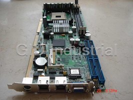
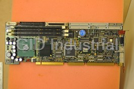
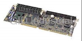
Kontron PCI-749D Full Size Single Board Computer - Socket 478 Intel Pentium 4 Support, PS/2, CF, Dual-LAN, VGA
Part Number
PCI-749D
Price
Request Quote
Manufacturer
KONTRON
Lead Time
Request Quote
Category
SLOT CPU/PICMG BOARDS » PICMG 1.0 SBC (PCI/ISA)
Specifications
Board Type
Full Size
Processor
Intel Pentium 4
Datasheet

Extracted Text
PCI-749D User Manual V1.1 ...... a allw wa ay ys s a a J Ju um mp p a ah he ea ad d! ! PCI-749D User’s Manual Version 1.1 PCI-749D User’s Manual Copyright notice © Copyright 2002,. All rights reserved. This document is copyrighted and all rights are reserved. The information in this document is subject to change without prior notice to make improvements to the products. This document contains proprietary information and protected by copyright. No part of this document may be reproduced, copied, or translated in any form or any means without prior written permission of the manufacturer. All trademarks and/or registered trademarks contains in this document are property of their respective owners including but not limited to the following. Intel, Socket 478, Willamette, Northwood, mPGA478, Pentium 4, Intel PRO/100 are registered trademarks of Intel Corporation. AwardBIOS is a trademark of Phoenix Software Corporation. IBM, PC, AT, VGA, and PC/2 are registered trademarks of International Business Machine Corporation. Microsoft, Windows, MS-DOS, Windows 95, Windows 98, Windows NT, Windows ME, Windows 2000 and Windows XP are registered trademarks of Microsoft Corporation. Promise, FastTrak100, and FastBuild are registered trademarks of Promise Technology, Inc.. Novell is a trademark of Novell ® Corporation. M-systems, DiskOnChip 2000, TrueFFS,, Millennium and IDE Pro are registered trademarks of M-Systems Inc.. 2 PCI-749D User’s Manual Packing List Hardware CPU Card (Single Board Computer) .......................................X 1 Cable Kit IDE Flat Cable .........................................................................X 1 FDD Cable...............................................................................X 1 DB9 COM and DB25 LPT Cable (for VL version) ...................X 1 Dual DB9 COM Cable (for VL2 version)..................................X 1 DB25 LPT Cable (for VL2 version)..........................................X 1 Dual USB Cable ......................................................................X 2 PS/2 Keyboard and Mouse Cable ...........................................X 1 UltraATA/100 IDE Cable..........................................................X 1 ATX Cable (3 to 4-pin).............................................................X 1 Audio Cable.............................................................................X 1 Printed Matter and Software Driver and User’s Manual CD..................................................X 1 3 PCI-749D User’s Manual Table of Contents Packing List 3 Chapter 1. Introduction 7 1.1 Product Overview 7 1.2 Specification 9 1.3 Component Placement 12 Chapter 2. Hardware Setup 13 2.1 Jumper and Connector Location 13 2.2 CPU and DRAM Setting 16 2.3 CMOS Setting 16 2.4 Watchdog Timer Setting 17 2.5 Embedded Solid State Disk 18 2.6 Power and Fan Connector 20 2.7 VGA Interface 21 2.8 Ethernet Interface 22 2.9 Audio Interface 23 2.10 Switch and Indicator 24 Chapter 3. BIOS Setup 25 Chapter 4. Driver Installation 27 Appendix. A I/O Port Pin Assignment 29 A.1 IDE Port 29 A.2 FDD Port 30 A.3 Parallel Port 31 A.4 Serial Port 32 A.5 USB Port 33 A.6 IrDA Port 33 A.7 VGA Port 34 A.8 LAN Port 34 4 PCI-749D User’s Manual A.9 AT Keyboard Port 35 A.10 PS/2 Keyboard and Mouse Port 35 pendix B. Flash the BIOS 37 B.1 BIOS Auto Flash Tool 37 B.2 Flash Method 37 Appendix C. System Resources 39 C.1 I/O Port Address Map 39 C.2 Memory Address Map 40 C.3 System IRQ and DMA Resource 41 5 PCI-749D User’s Manual Notes(This page left blank intentionally) 6 PCI-749D User’s Manual Chapter 1. Introduction 1.1 Product Overview The SBC (Single Board Computer) is an all-in-one industrial full-size PICMG architecture. (PCI/ISA)-bus CPU card based on Intel mPGA478 Pentium 4 With Intel Brookdale-G chipset, PCI-749D offers the value solution with Intel NetBurst micro-architecture, 533/400 MHz of FSB, 2 GB PC1600/2100 DDR SDRAM, Intel Brookdale-G GMCH built-in advanced 3D SVGA, and dual Intel PRO/100+ LAN and USB 2.0 high speed I/O interfaces. Based on Intel's long term supply chipset, PCI-749D should be the ideal solution for long life industrial applied computing platform with high computing capacity and cost effect. The onboard dual Intel PRO/100+ LAN, CompactFlash SSD (Solid State Disk), and ISA 64mA high drive capacity also make PCI-749D be the value Pentium 4 DDR platform for: Value Industrial Computing Platform: Intel mPGA478 Pentium 4 / Celeron CPU with 533/400 MHz FSB and 2 GB PC1600/2100 DDR SDRAM of system memory, PCI-749D offer the high-end industrial computing platform with low cost Intel integrated solution. The long term support, onboard SSD, dual Intel LAN and ISA 64mA high drive capacity also make PCI-749D be the ideal solution for industrial server and workstation, CTI (Computer Telephony Integration), VoIP (Voice over IP), and other high-end applications. Low Cost Multi-media Solution: Intel Brookdale-G chipset built-in advanced 3D VGA controller offers the value integration solution for low cost multi-media computing platform. Such as VoD (video on demand), DVR (Digital Video Recorder), digital video broadcasting (DVB), streaming, surveillance, compression (MPEG), interaction server, workstation and terminal appliances. Redundant Network Reliability: dual Intel PRO/100+ 10/100 Mbps Fast Ethernet interfaces for high reliability of redundant LAN, or external / internal dual direction networking applications. High Speed USB 2.0 Interface: Intel ICH4 built-in USB 2.0 controller let PCI-749D offer the high speed USB 2.0 interface with 480 Mbps of data transfer rate. It makes PCI-749D be the platform to link with high-end USB 7 PCI-749D User’s Manual 2.0 devices including digital camera, USB hard disk, and other USB 2.0 based peripherals. 8 PCI-749D User’s Manual 1.2 Specification General Specification Form Factor Full-size PICMG-bus CPU Card / Slot PC PICMG version 1.0 (Rev. 2.0). CPU Intel mPGA478 Pentium 4, Celeron @ 533/400 MHz FSB Support Northwood / Willamette Pentium 4 / Celeron Memory 2 GB DDR200/266 (PC1600/2100 DDR) SDRAM on 2 x 184-pin DIMM sockets. (No ECC/register DIMM support) Chipset Intel 82845G GMCH and 82801DB ICH4 BIOS Phoenix-Award 2Mb PnP flash BIOS Green Function Power saving mode supported in BIOS with DOZE, STANDBY and SUSPEND modes. ACPI version 1.0 and APM version 1.2 compliant Watchdog Timer Generates NMI or system reset programmable watchdog timer with 1 ~ 255 sec. / min. of time out value Real Time Clock Intel ICH4 built-in RTC with lithium battery Enhanced IDE PCI enhanced IDE interface supports dual ports up to 4 ATAPI devices with UltraATA/100 supported ISA High Drive ISA 64mA high Drive capacity with TI 245 buffer on address and data bus Multi-I/O Ports Chipset Intel 82801DB ICH4 and Winbond W83627HF-AW LPC super-I/O controller Serial Port Two RS-232 serial ports. Both with 16C550 compatible UART and 16 bytes FIFO USB Port Four USB 2.0 ports with 480 Mbps of data transfer rate Parallel Port One bi-direction parallel port with SPP/ECP/EPP mode FDD One FDD port supports up to two FDD IrDA Port One IrDA compliant Infrared interface supports SIR K/B & Mouse PS/2 keyboard and mouse ports, AT keyboard port 9 PCI-749D User’s Manual Solid State Disk Interface Flash Type Onboard CompactFlash Type-II socket Mode Bootable, primary master IDE channel Package CompactFlash card (CFC) or IBM MicroDrive Capacity Up to 1 GB VGA Display Interface Chipset Intel 845G GMCH built-in 256-bit 3D VGA controller Video Memory Auto detect dynamic video memory up to 64 MB Display Type CRT, LCD monitor and analog display Connector External DB15 female connector on bracket for CRT Internal 16-pin header for analog VGA display Ethernet Interface Chipset Dual Intel PRO/100+ LAN interface Primary LAN (LAN1): Intel ICH4 and Intel 82562ET Optional secondary LAN (LAN2): Intel 82559ER Type 10Base-T / 100Base-TX, auto-switching Fast Ethernet Full duplex, IEEE802.3U compliant Connector External (dual) RJ45 with LED on bracket Audio Interface Chipset Intel ICH4 built-in AC97 3D audio controller with codec Interface Line-in, line-out, CD-in, Mic-in Connector 10-pin header for line-in, line-out and Mic-in 4-pin header for CD-in 10 PCI-749D User’s Manual Power and Environment Power Req. +5V, +12V, -12V DC input from PICMG backplane Additional +12V on 4-pin connector for Pentium 4 PSU ATX Function 3-pin ATX interface with 5V standby and power-on Dimension 338 (L) x 122 (H) mm, standard PICMG form factor o o Temperature Operating within 0 ~ 60 C (32 ~ 140 F) o o Storage within -20 ~ 85 C (-4 ~ 185 F) Humidity: 5% ~ 95% non-condensing Ordering Code PCI-749D-VL2 Full-size PICMG mPGA478 DDR CPU Card with 533/400 MHz FSB, Intel VGA, Dual LAN, Audio, USB 2.0, CF Interfaces and ISA 64mA High Drive Capacity 11 PCI-749D User’s Manual 1.3 Component Placement CompactFlash Socket System Memory Intel 845G GMCH Support CFC and 2 x 184-pin DIMM Socket Built-in Extreme IBM MicroDrive 2 GB DDR SDRAM 256-bit 3D VGA mPGA478 CPU Socket Intel 82801DB ICH4 Dual Intel PRO/100+ LAN Intel Pentium 4 / Celeron Built-in USB 2.0 Port Intel ICH4 + 82562ET 533/400 MHz FSB AC97 3D Audio and Intel 82559ER 12 PCI-749D User’s Manual Chapter 2. Hardware Setup This chapter contains the information for installation of hardware. The install procedure includes jumper settings, CPU and memory installation, fan, I/O and panel connections. 2.1 Jumper and Connector Location FDD IDE2 LPT IDE1 SYSFAN ATXREG CN1 JVGA JWDT JFRNT DIMM1 JDOM USB2 JPS DIMM2 JRTC USB1 VGA LAN1 LAN2 PS2 JIR CPUFAN CPU CDIN JAUDIO JCFSEL JATKB JCOM1 CF J82559 JCOM2 Color Definition of Jumper Hat - Red : Power or Important Setting - Yellow : Function Enable / Disable Setting - Green : CPU Speed Setting (Not Available) 13 PCI-749D User’s Manual 2.1.1 Jumpers Reference Jumper Function Section JRTC COMS Operate / Clear Setting 2.3 JWDT Watchdog Timer NMI / Reset Setting 2.4 JCFSEL CompactFlash Mode Setting 2.5 JDOM DiskOnModule SSD Power Setting 2.5 J82559 Secondary LAN Enable/Disable Setting 2.8 14 PCI-749D User’s Manual 2.1.2 Connectors Reference Internal Onboard Connector Connector Function Remark CPU MicroPGA478 478 CPU Socket Standard DIMM1/2 184-pin DIMM Socket Standard IDE1/2 40-pin Primary / Secondary IDE Port Standard FDD 34-pin FDD Port Standard LPT 26-pin Parallel Port Standard JCOM1/2 10-pin COM1/2 Serial Port Standard USB1/2 10-pin 1st / 2nd (3rd / 4th) USB Port Standard JIR 5-pin SIR IrDA Port Standard CF CompactFlash Socket Standard JATKB 5-pin AT Keyboard Connector Standard ATXREG 4-pin Additional +12V Power Connector Standard JPS 3-pin ATX Signal Connector Standard JFRNT 14-pin Switch and Indicator Connector Standard CPUFAN 3-pin +12V CPU Fan Connector Standard SYSFAN 3-pin +12V System Fan Connector Standard JVGA 16-pin Internal VGA Port Standard JAUDIO 10-pin Audio Port Standard CDIN 4-pin CD-in Interface Standard CN1 3-pin Wake-On-LAN Interface Standard External Connector on Bracket Connector Function Remark VGA DB15 Female VGA Connector Standard LAN1 RJ45 LAN1 Connector Standard LAN2 RJ45 LAN2 Connector VL2 only COM1 DB9 Male COM1 Connector VL only PS2 6-pin MiniDIN PS/2 Keyboard & Mouse Standard 15 PCI-749D User’s Manual 2.2 CPU and DRAM Setting The board is based on Intel Socket 478 architecture, supports Intel mPGA478 Pentium 4 / Celeron CPU at 533/400 MHz FSB. The board is based on Intel 845G GMCH, supports 533 and 400 MHz FSB of Intel 0.13 micron Northwood and 0.18 micron Willamette CPU. System memory of this board supports up to 2 GB DDR200/266 (PC1600/2100) SDRAM on 2 184-pin DIMM sockets. Please notices that Intel 845G GMCH doesn’t support ECC and register DIMM. 2.3 CMOS Setting The board’s data of CMOS can be setting in BIOS. If the board refuses to boot due to inappropriate CMOS settings, here is how to proceed to clear (reset) the CMOS to its default values. Jumper: JRTC Type: onboard 3-pin header JRTC Mode 1-2 Clear CMOS 2-3 Normal Operation Default setting JRTC 1 2 3 16 PCI-749D User’s Manual 2.4 Watchdog Timer Setting The watchdog timer makes the systems auto-reset while it stop to work for a period. The onboard watchdog timer can be setup as system reset or active NMI mode by jumper JWDT. Jumper: JWDT Type: onboard 3-pin header JWDT Watchdog Timer 1-2 Active NMI 2-3 Reset Default setting JWDT 1 2 3 Program Sample Watchdog timer setup as system reset with 5 second of timeout 2E, 87 2E, 87 2E, 07 2F, 08 Logical Device 8 2E, 30 Activate 2F, 01 2E, F5 Set as Second* 2F, 00 2E, F6 Set as 5 2F, 05 * Minute: bit 3 = 0; Second: bit 3 = 1 17 PCI-749D User’s Manual 2.5 Embedded Solid State Disk The board supports both of IDE-based CompactFlash and M-systems DiskOnChip IDE Pro and DiskOnModule (DOM) embedded flash disk. The onboard CompactFlash type-II socket supports CompactFlash card (CFC) and IBM MicroDrive flash disk on primary IDE channel with jumper selectable master / slave mode. The onboard secondary IDE port with 40-pin IDE2 box header supports normal DOM (DiskOnModule) or M-systems DiskOnChip IDE Pro flash disk with jumper selectable +5V Vcc power for cable free applications on jumper JDOM. JDOM 1 2 JCFSEL 12 3 CompactFlash Mode Setting Jumper: JCFSEL Type: onboard 3-pin header JCFSEL CompactFlash Mode 1-2 Master 2-3 Slave Default setting Boot from CompactFlash Setting The board is bootable from the CompactFlash. The hardware setting of booting from CompactFlash is as below. 1. Setting JCFSEL as 2-3 closed, to let the CompactFlash be the primary master IDE mode. 2. Setting the first boot device as HDD-0 on the BIOS (Advanced BIOS Feature Setup) 18 PCI-749D User’s Manual DOM or DiskOnChip 2000 IDE Pro Power Setting Jumper: JDOM Type: onboard 2-pin header JDOM +5V on Pin-20 of IDE2 OFF Disable ON Enable Default setting 19 PCI-749D User’s Manual 2.6 Power and Fan Connector ATXREG 31 42 JPS 13 CPUFAN SYSFAN 123 Connector: ATXREG Type: 4-pin Standard Pentium 4 Additional +12V Power Connector Pin Description Pin Description 1 Ground 2 Ground 3 +12V 4 +12V Connector: JPS Type: 3-pin ATX Function Connector Pin Description Pin Description Pin Description 1 5V Standby 2 Ground 3 Power On Connector: CPUFAN, SYSFAN Type: 3-pin Fan Power Wafer Connector Pin Description Pin Description Pin Description 1 Ground 2 +12V 3 Fan Control 20 PCI-749D User’s Manual 2.7 VGA Interface The board is integrated with Intel 845G GMCH chipset’s built-in extreme VGA controller with 256-bit 3D engine and dynamic video memory up to 64 MB shared with system memory. The CRT / analog VGA interface includes one external DB15 female connector on bracket and one internal 16-pin header on board. JVGA 19 8 16 Connector: JVGA Type: 16-pin header Pin Description Pin Description 1 Red 9 Green 2 Blue 10 N/C 3 Ground 11 Ground 4 Ground 12 Ground 5 N/C 13 Ground 6 N/C 14 Data 7 HSYNC 15 VSYNC 8 Clock 16 N/C 21 PCI-749D User’s Manual 2.8 Ethernet Interface The board integrated with dual Intel PRO/100+ Fast Ethernet interfaces at the type of 10Base-T/100Base-TX auto-switching Fast Ethernet with full duplex and IEEE 802.3U compliant. Both of them connect via RJ45 connectors on bracket. The LAN2 can enable or disable by jumper J82559. The primary LAN interface is controlled by Intel ICH4 with Intel 82562ET and setting as LAN1. It provides the same performance as Intel 82559 LAN with the same driver. The OPTIONAL secondary LAN interface is controlled by Intel 82559ER chipset and setting as LAN2. Jumper: J82559 Type: onboard 3-pin header J82559 LAN2 Enable / Disable Setting 1-2 Enable 2-3 Disable Default setting CN1 1 2 3 J82559 13 Connector: CN1 Type: onboard 3-pin header Wake-On-LAN connector Pin 1 2 3 Description WOL-Ctrl Ground +5V Standby 22 PCI-749D User’s Manual 2.9 Audio Interface The board integrates with AC97 3D audio interface by Intel ICH4 and codec, provides line-in, line-out, Mic-in and CD-in interfaces for industrial applications with audio function. CDIN 1 2 3 4 JAUDIO 10 2 9 1 Connector: JAUDIO Type: 10-pin header Pin Description Pin Description 1 Line – Right 2 Ground 3 Line – Left 4 MIC 5 MIC 6 Ground 7 N/C 8 Line Out – Left 9 Line Out – Right 10 Ground Connector: CDIN Type: 4-pin header Pin Description 1 CD – Left 2 Ground 3 Ground 4 CD – Right 23 PCI-749D User’s Manual 2.10 Switch and Indicator JFRNT JFRNT 2 14 1 13 Connector: JFRNT Type: onboard 14-pin header Function Signal PIN Signal Function Vcc (+) 1 2 (+) Vcc IDE LED Power Active 3 4 N/C LED Reset 5 6 GND Reset GND 7 8 Vcc N/C 9 10 N/C Speaker Power PWRBT 11 12 N/C Button GND 13 14 SPKIN 24 PCI-749D User’s Manual Chapter 3. BIOS Setup The single board computer uses the Award BIOS for the system configuration. The Award BIOS in the single board computer is a customized version of the industrial standard BIOS for IBM PC AT-compatible computers. It supports Intel x86 and compatible CPU architecture based processors and computers. The BIOS provides critical low-level support for the system central processing, memory and I/O sub-systems. The BIOS setup program of the single board computer let the customers modify the basic configuration setting. The settings are stored in a dedicated battery-backed memory, NVRAM, retains the information when the power is turned off. If the battery runs out of the power, then the settings of BIOS will come back to the default setting. The BIOS section of the manual is subject to change without notice and is provided here for reference purpose only. The settings and configurations of the BIOS are current at the time of print, and therefore they may not be exactly the same as that displayed on your screen. To activate CMOS Setup program, press <DEL> key immediately after you turn on the system. The following message “Press DEL to enter SETUP” should appear in the lower left hand corner of your screen. When you enter the CMOS Setup Utility, the Main Menu will be displayed as Figure 3-1. You can use arrow keys to select your function, press <Enter> key to accept the selection and enter the sub-menu. Figure 3-1. CMOS Setup Utility Main Screen Phoenix – Award BIOS CMOS Setup Utility >Standard CMOS Features >Frequency/Voltage Control >Advanced BIOS Features Load Fail-Safe Defaults >Advanced Chipset Features Load Optimized Defaults >Integrated Peripherals Set Supervisor Password >Power Management Setup Set User Password >PnP / PCI Configurations Save & Exit Setup >PC Health Status Exit Without Saving Esc : Quit ↑ ↓ → ← : Select Item F10 : Save & Exit Setup 25 PCI-749D User’s Manual Notes (This page left blank intentionally) 26 PCI-749D User’s Manual Chapter 4. Driver Installation The driver CD offers auto-run menu. It will detect and select the type of single board computer and helps you install the drivers automatically. Install Board’s Software The selection helps you install the drivers of chipset. It will detect your version of OS automatically. Install Ultra ATA IDE Driver The selection helps you to install the driver of IDE interface. Install VGA Driver The selection helps you to install the driver of onboard VGA interface. Install LAN Driver The selection helps you to install the driver of onboard LAN interface. Install Audio Driver The selection helps you to install the driver of onboard audio interface. Install USB 2.0 Driver The selection helps you to install the driver of onboard USB 2.0 interface. Link to < Website > Homepage The selection helps you to link to the website to find the updated technical documents and download directly. Browse this CD The selection helps you to find the drivers in this CD directly. 27 PCI-749D User’s Manual Notes (This page left blank intentionally) 28 PCI-749D User’s Manual Appendix. A I/O Port Pin Assignment A.1 IDE Port 2 40 Connector: IDE1, IDE2 1 39 Type: 40-pin (2 x 20) box header Pin Description Pin Description 1 Reset 2 Ground 3 D7 4 D8 5 D6 6 D9 7 D5 8 D10 9 D4 10 D11 11 D3 12 D12 13 D2 14 D13 15 D1 16 D14 17 D0 18 D15 19 Ground 20 N/C (Vcc) 21 REQ 22 Ground 23 IOW-/STOP 24 Ground 25 IOR-/HDMARDY 26 Ground 27 IORDY/DDMARDY 28 IDESEL 29 DACK- 30 Ground 31 IRQ 32 N/C 33 A1 34 CBLID 35 A0 36 A2 37 CS0 (MASTER CS) 38 CS1 (SLAVE CS) 39 LED ACT- 40 Ground The pin-20 is N/C on IDE1 and is jumper selectable N/C or +5V on IDE2. 29 PCI-749D User’s Manual A.2 FDD Port 1 Connector: FDD 2 Type: 34-pin (2 x 17) header Pin Description Pin Description 1 Ground 2 DRIVE DENSITY SELECT 0 3 Ground 4 DRIVE DENSITY SELECT 1 5 Ground 6 N/C 7 Ground 8 INDEX- 9 Ground 10 MOTOR ENABLE A- 11 Ground 12 DRIVER SELECT B- 13 Ground 14 DRIVER SELECT A- 15 Ground 16 MOTOR ENABLE B- 17 Ground 18 DIRECTION- 19 Ground 20 STEP- 21 Ground 22 WRITE DATA- 23 Ground 24 WRITE GATE- 25 Ground 26 TRACK 0- 27 Ground 28 WRITE PROTECT- 29 Ground 30 READ DATA- 31 Ground 32 HEAD SELECT- 33 Ground 34 DISK CHANGE- 30 PCI-749D User’s Manual A.3 Parallel Port 1 Connector: LPT 14 Type: 26-pin box header Pin Description Pin Description 1 STROBE- 14 AUTO FEED- 2 D0 15 ERROR- 3 D1 16 INITIALIZE- 4 D2 17 SELECT INPUT- 5 D3 18 Ground 6 D4 19 Ground 7 D5 20 Ground 8 D6 21 Ground 9 D7 22 Ground 10 ACKNOWLEDGE- 23 Ground 11 BUSY 24 Ground 12 PAPER EMPTY 25 Ground 13 SELECT+ 26 N/C 31 PCI-749D User’s Manual A.4 Serial Port A.4.1 Onboard RS-232C Serial Port 1 Connector: JCOM1, JCOM2 2 Type: 10-pin header Pin Description Pin Description 1 DCD 2 RXD 3 TXD 4 DTR 5 Ground 6 DSR 7 RTS 8 CTS 9 RI 10 N/C A.4.2 On Bracket RS-232C Serial Port 5 9 4 8 3 Connector: COM1 (VL only) 7 2 6 Type: 9-pin D-sub male connector on bracket 1 Pin Description Pin Description 1 DCD 2 RXD 3 TXD 4 DTR 5 Ground 6 DSR 7 RTS 8 CTS 9 RI 32 PCI-749D User’s Manual A.5 USB Port 51 Connector: USB1, USB2 Type: 10-pin (2 x 5) header for dual USB Ports 10 6 Pin Description Pin Description 1 Vcc 6 Vcc 2 Data0- 7 Data1- 3 Data0+ 8 Data2+ 4 Ground 9 Ground 5 Ground 10 Ground A.6 IrDA Port Connector: JIR Type: 5-pin (1 x 5) header for SIR Port 15 Pin Description 1 Vcc 2 N/C 3 IRRX 4 Ground 5 IRTX 33 PCI-749D User’s Manual 6 A.7 VGA Port 1 11 2 12 3 13 Connector: VGA 4 14 5 15 Type: 15-pin D-sub female connector on bracket 10 Pin Description Pin Description Pin Description 1 RED 6 Ground 11 N/C 2 GREEN 7 Ground 12 VDDAT 3 BLUE 8 Ground 13 HSYNC 4 N/C 9 Vcc 14 VSYNC 5 Ground 10 Ground 15 VDCLK A.8 LAN Port 1 Connector: LAN1, LAN2 Type: RJ45 connector on bracket 8 Pin 1 2 3 4 5 6 7 8 Description TX+ TX- RX+ N/C N/C RX- N/C N/C 34 PCI-749D User’s Manual A.9 AT Keyboard Port 1 Connector: JATKB 5 Type: 5-pin box header Pin 1 2 3 4 5 Description CLK DATA N/C Ground Vcc A.10 PS/2 Keyboard and Mouse Port 3 1 5 Connector: PS2 6 2 Type: 6-pin MiniDIN connector on bracket 4 Pin 1 2 3 4 5 6 Description KBD MSD Ground N/C KBC MSC Note: The PS/2 connector supports standard PS/2 keyboard directly or both PS/2 keyboard and mouse through the PS/2 Y-type cable. The cable is the standard on packing list. 35 PCI-749D User’s Manual Note(This page left blank intentionally) 36 PCI-749D User’s Manual pendix B. Flash the BIOS B.1 BIOS Auto Flash Tool The board is based on Award BIOS and can be updated easily by the BIOS auto flash tool. You can download the tool online at the address below: http://www.award.com File name of the tool is “awdflash.exe”, it’s the utility that can write the data into the BIOS flash ship and update the BIOS. B.2 Flash Method 1. Get the “.bin” file including the image of new BIOS you want to update. 2. Power on the system and flash the BIOS. 3. Re-star the system. Any question about the BIOS re-flash please contact your distributors or visit the website of the original manufacturer. 37 PCI-749D User’s Manual Notes(This page left blank intentionally) 38 PCI-749D User’s Manual Appendix C. System Resources C.1 I/O Port Address Map Address Range Device 0060-0060 i8042prt 0064-0064 i8042prt 0170-0177 atapi 01CE-01CF VgaSave 01F0-01F7 atapi 02F8-02FE Serial 0376-0376 atapi 0378-037A Parport 0380-038B VgaSave 03C0-03DF VgaSave 03F0-03F5 Floppy 03F6-03F6 atapi 03F7-03F7 Floppy 03F8-03FE Serial C000-C03F E100B C400-C41D E100E E000-E0EF alcxnt E400-E43F alcxnt 39 PCI-749D User’s Manual C.2 Memory Address Map Device Physical Address Length x00000000 - x0009FFFF System board extension for PnP BIOS x000A0000 - x000AFFFF Intel(R) 82845G Graphics Controller x000B0000 - x000BFFFF Intel(R) 82845G Graphics Controller x000C0000 - x000CADFF Intel(R) 82845G Graphics Controller x000CAE00 - x000CBFFF Motherboard resources x000F0000 - x000F3FFF Motherboard resources x000F4000 - x000F7FFF Motherboard resources x000F8000 - x000FFFFF Motherboard resources x00100000 - x00FFFFFF System board extension for PnP BIOS xE0000000 - xE7FFFFFF Intel(R) 82845G Graphics Controller xE8000000 - xEBFFFFFF Intel(R) 82845G Processor to I/O Controller 2560 xEC000000 - xEC1FFFFF Intel(R) 82801DB PCI Bridge - 244E xEC100000 - xEC11FFFF Intel(R) GD82559ER PCI Adapter xEC120000 - xEC120FFF Intel(R) PRO/100 VE Network Connection xEC121000 - xEC121FFF Intel(R) GD82559ER PCI Adapter xEC200000 - xEC27FFFF Intel(R) 82845G Graphics Controller xEC280000 - xEC2803FF Intel (R) USB Enhanced Host Controller (ICH4) xEC281000 - xEC2811FF Avance AC97 Audio xEC282000 - xEC2820FF Avance AC97 Audio xFEC00000 - xFEC0FFFF System board extension for PnP BIOS xFEE00000 - xFEE0FFFF System board extension for PnP BIOS xFFB00000 - xFFB7FFFF System board extension for PnP BIOS xFFB80000 - xFFBFFFFF Intel(r) 82802 Firmware Hub Device xFFF00000 - xFFFFFFFF System board extension for PnP BIOS 40 PCI-749D User’s Manual C.3 System IRQ and DMA Resource C.3.1 IRQ IRQ Number Device 0 System timer 1 Standard 101/102-Key or Microsoft Natural Keyboard 2 Programmable interrupt controller 3 Communications Port (COM2) 4 Communications Port (COM1) 5 Intel(R) 82801DB/DBM USB Universal Host Controller - 24C2 5 IRQ Holder for PCI Steering 5 Intel(R) 82845G/GL Graphics Controller 6 Standard Floppy Disk Controller 7 Printer Port (LPT1) 8 System CMOS/real time clock 9 Intel (R) USB Enhanced Host Controller (ICH4) 9 IRQ Holder for PCI Steering 10 Avance AC97 Audio 10 Intel(R) 82801DB/DBM SMBus Controller - 24C3 10 Intel(R) GD82559ER PCI Adapter 10 Intel(R) 82801DB/DBM USB Universal Host Controller - 24C4 10 IRQ Holder for PCI Steering 11 Intel(R) PRO/100 VE Network Connection 11 Intel(R) 82801DB/DBM USB Universal Host Controller - 24C7 11 IRQ Holder for PCI Steering 12 PS/2 Compatible Mouse Port 13 Numeric data processor 14 Primary IDE controller (dual fifo) 14 Intel(R) 82801DB Ultra ATA Storage Controller - 24CB 15 Secondary IDE controller (dual fifo) 15 Intel(R) 82801DB Ultra ATA Storage Controller - 24CB 41 PCI-749D User’s Manual C.3.2 DMA Channel Device 0 (free) 1 (free) 2 Standard Floppy Disk Controller 3 (free) 4 Direct Memory Access Controller 5 (free) 6 (free) 7 (free) 42 ...... a allw wa ay ys s a a J Ju um mp p a ah he ea ad d! !
Frequently asked questions
What makes Elite.Parts unique?

What kind of warranty will the PCI-749D have?
Which carriers does Elite.Parts work with?
Will Elite.Parts sell to me even though I live outside the USA?
I have a preferred payment method. Will Elite.Parts accept it?
Why buy from GID?

Quality
We are industry veterans who take pride in our work

Protection
Avoid the dangers of risky trading in the gray market

Access
Our network of suppliers is ready and at your disposal

Savings
Maintain legacy systems to prevent costly downtime

Speed
Time is of the essence, and we are respectful of yours
Related Products
Kontron P3S440BXS/850 CPU Board. Pentium III 800MHz CPU | LAN | IDE | USB | Serial & Parallel Ports ...

Request a Quote

The quote request has been received
Close

Facing challenges or have inquiries? Feel free to contact us!
Call Us +1-469-283-2440
What they say about us
FANTASTIC RESOURCE
One of our top priorities is maintaining our business with precision, and we are constantly looking for affiliates that can help us achieve our goal. With the aid of GID Industrial, our obsolete product management has never been more efficient. They have been a great resource to our company, and have quickly become a go-to supplier on our list!
Bucher Emhart Glass
EXCELLENT SERVICE
With our strict fundamentals and high expectations, we were surprised when we came across GID Industrial and their competitive pricing. When we approached them with our issue, they were incredibly confident in being able to provide us with a seamless solution at the best price for us. GID Industrial quickly understood our needs and provided us with excellent service, as well as fully tested product to ensure what we received would be the right fit for our company.
Fuji
HARD TO FIND A BETTER PROVIDER
Our company provides services to aid in the manufacture of technological products, such as semiconductors and flat panel displays, and often searching for distributors of obsolete product we require can waste time and money. Finding GID Industrial proved to be a great asset to our company, with cost effective solutions and superior knowledge on all of their materials, it’d be hard to find a better provider of obsolete or hard to find products.
Applied Materials
CONSISTENTLY DELIVERS QUALITY SOLUTIONS
Over the years, the equipment used in our company becomes discontinued, but they’re still of great use to us and our customers. Once these products are no longer available through the manufacturer, finding a reliable, quick supplier is a necessity, and luckily for us, GID Industrial has provided the most trustworthy, quality solutions to our obsolete component needs.
Nidec Vamco
TERRIFIC RESOURCE
This company has been a terrific help to us (I work for Trican Well Service) in sourcing the Micron Ram Memory we needed for our Siemens computers. Great service! And great pricing! I know when the product is shipping and when it will arrive, all the way through the ordering process.
Trican Well Service
GO TO SOURCE
When I can't find an obsolete part, I first call GID and they'll come up with my parts every time. Great customer service and follow up as well. Scott emails me from time to time to touch base and see if we're having trouble finding something.....which is often with our 25 yr old equipment.
ConAgra Foods