

 Manufacturers
KONTRON 1JEXPNE
Description
Kontron 1JEXPNE CPU Board - ETXexpress-PM no CPU with Gigabit Ethernet
Part Number
1JEXPNE
Price
Request Quote
Manufacturer
KONTRON
Lead Time
Request Quote
Category
PRODUCTS - 1
Specifications
95 x 125 mm
System
Chipset Integrated
4 PCI Express x1 (3 PCI Express x1 for GbE version), 1 PEG x16
Environment
Temperature: operation: 0° to 60°C, storage: -10° to 85°C
Expansion BUS
10/100 MBit Ethernet (or Gigabit Ethernet)
Form Factor / Pin-out Type
Fully COM Express Type 2 compliant
Hard Disk
2 x Serial ATA, 1 x Parallel ATA 100
Humidity
Operation: 10% to 90%, Storage: 5% to 95%
LVDS Panel Support
Single and Dual Channel LVDS 18/24 bit, Dual SDVO
Max Data Transfer Rate
Up to 2GB (400/533) DDR2 SODIMM
Other Features
E²PROM BIOS Setup, LAN Boot, JRC support, I²C Bus, RTC, Watchdog, JIDA Support, IrDA enhanced
PCI 2.3, 32 bit / 33 MHz PCI bus
System
Power Requirement
typ. Idle 13,3W Pentium LV738
Processor
Intel Pentium M
Intel Pentium M and Intel Celeron M Processor, socket or soldered
QSXGA 2048x1536 32 Bit
System
RTC
XGA 1024x786 32 Bit, SXGA 1280x1024 32 Bit,
Serial
Intel High Definition Audio / AC97
TV out / HDTV Resolution
TV out on seperate set of pins (component video or composite video)
USB
8x USB 2.0 Ports for external peripherals
VRAM
Integrated with Intel Graphics Media Accelerator (GMA 900) or expand via 1 PEG x16
Features
- Best performance with latest interface technologies
- Equipped with the upcoming primary datapath PCI Express
- Intel Extreme Graphics and PCI Express Graphic
- SerialATA for highspeed drives
- USB 2.0 for fast peripherals
Datasheet

Extracted Text
ETXexpress-PM
User’s Guide
Document Revision: 1.4
February 2007
Kontron America
Customer Service
Mailing Address: Kontron - United States
14118 Stowe Drive
Poway, CA 92064 USA
Tel: 858-677-0877
Fax: 858-677-0895
Technical Support: U.S. and Canadian Customers - 24 hours a day
Tel: +1 (510)-661-2220
Fax: +1 (510)-490-2360
International Customers - 9am to 4pm local time
Tel: (+49) (0) 991-37024-0
Fax: (+49) (0) 991-37024-109
Visit our site at: www.kontron.com
Copyright © 2005-2007 Kontron Embedded Modules GmbH
All rights reserved. No part of this manual may be reproduced, transmitted, transcribed,
stored in a retrieval system, or translated into any language or computer language, in
any form or by any means (electronic, mechanical, photocopying, recording, or
otherwise), without the express written permission of Kontron Embedded Modules
GmbH.
DIMM-PC®, PISA®, ETX®, ETXexpress® , X-board®, DIMM-IO® and DIMM-BUS® are
trademarks or registered trademarks of Kontron Embedded Modules GmbH. Kontron is
trademark or registered trademark of Kontron AG.
All trademarks, registered trademarks, and trade names used in this user’s guide are
the property of their respective owners. This user’s guide contains information
proprietary to Kontron.
The information in this user’s guide is provided for reference only. Kontron does not
assume any liability arising out of the application or use of the information or products
described herein. This user’s guide may contain or reference information and products
protected by copyrights or patents and does not convey any license under the patent
rights of Kontron, nor the rights of others.
Kontron reserves the right to make changes without notice in product or component
design as warranted by evolution in user needs or progress in engineering or
manufacturing technology. Changes which affect the operation of the unit will be
documented in the next revision of this user’s guide.
page 2 ETXexpress-PM User’s Guide
Table Of Contents
1. User Information ....................................................................................................... 7
About This Manual ....................................................................................................................7
Copyright Notice................................................................................................................................... 7
Trademarks .......................................................................................................................................... 7
Standards............................................................................................................................................. 7
Advisory Conventions .......................................................................................................................... 8
Guarantee and Warranty Policy ................................................................................................9
Guarantee ............................................................................................................................................ 9
Limited Warranty .................................................................................................................................. 9
Return Procedure............................................................................................................................... 10
Limitation of Liability........................................................................................................................... 10
Technical Support ...................................................................................................................11
2. Getting Started ........................................................................................................ 13
Before You Begin ....................................................................................................................13
Unpacking .......................................................................................................................................... 13
When Working Inside a Computer ..................................................................................................... 14
Preventing Electrostatic Discharge .................................................................................................... 14
3. Introduction............................................................................................................. 17
ETXexpress-PM ......................................................................................................................17
ETXexpress-PM Module Overview .........................................................................................18
Understanding ETXexpress Functionality..........................................................................................19
ETXexpress Reference Documents................................................................................................... 19
About PCI Express..................................................................................................................20
Thermal Management .............................................................................................................20
Heat-spreader Plate ........................................................................................................................... 20
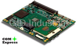
Photos .....................................................................................................................................21
Block Diagram.........................................................................................................................22
4. Specifications.......................................................................................................... 23
Functional Specifications.........................................................................................................23
Mechanical Specifications .......................................................................................................26
Dimensions......................................................................................................................................... 26
Electrical Specifications...........................................................................................................28
Environmental Specifications ..................................................................................................28
5. CPU, Chipset, Super I/O and Memory ................................................................... 29
CPU.........................................................................................................................................29
Chipset ....................................................................................................................................29
Super I/O.................................................................................................................................31
Memory ...................................................................................................................................31
ETXexpress-PM User’s Guide page 3
6. Primary Connector (Rows A and B).......................................................................33
Advanced Configuration and Power Interface (ACPI) ............................................................ 33
Audio....................................................................................................................................... 34
Azalia ..................................................................................................................................................34
AC97...................................................................................................................................................34
Ethernet .................................................................................................................................. 35
Graphics ................................................................................................................................. 35
Flat Panel............................................................................................................................................35
CRT ....................................................................................................................................................36
LPC......................................................................................................................................... 36
Serial ATA............................................................................................................................... 37
USB 2.0 .................................................................................................................................. 37
7. Secondary Connector (Rows C and D)..................................................................39
PCI Express............................................................................................................................ 39
PCI.......................................................................................................................................... 40
IDE.......................................................................................................................................... 40
8. Super I/O Subsystems ............................................................................................41
Floppy Drive............................................................................................................................ 41
IrDA......................................................................................................................................... 41
PS/2 Keyboard........................................................................................................................ 42
PS/2 Mouse ............................................................................................................................ 42
Parallel Port ............................................................................................................................ 42
Serial Ports (1 and 2).............................................................................................................. 43
Watchdog Timer ..................................................................................................................... 43
9: System Resources ..................................................................................................45
Interrupt Request (IRQ) Lines................................................................................................. 45
APIC Mode .........................................................................................................................................45
8259 PIC Mode...................................................................................................................................46
Direct Memory Access (DMA) Channels ................................................................................ 47
Memory Area .......................................................................................................................... 47
I/O Address Map..................................................................................................................... 47
Peripheral Component Interconnect (PCI) Devices................................................................ 48
Inter-IC (I2C) Bus.................................................................................................................... 48
System Management (SM) Bus.............................................................................................. 48
10: BIOS .......................................................................................................................49
Introduction............................................................................................................................. 49
Determining the BIOS Version ...........................................................................................................49
Configuring the System BIOS................................................................................................. 50
Starting the Setup Utility .....................................................................................................................50
Main Menu.............................................................................................................................. 52
Advanced Menu...................................................................................................................... 52
page 4 ETXexpress-PM User’s Guide
CPU Configuration Menu ................................................................................................................... 52
IDE Configuration Menu..................................................................................................................... 53
Floppy Configuration Submenu.......................................................................................................... 53
Super I/O Configuration ..................................................................................................................... 54
ACPI Configuration ............................................................................................................................ 55
Event Log Configuration..................................................................................................................... 55
General Purpose Inputs/Outputs........................................................................................................ 56
Watchdog Timer................................................................................................................................. 56
Hardware Health Monitor Submenu................................................................................................... 57
MPS Configuration ............................................................................................................................. 57
PCI Express Configuration Submenu ................................................................................................ 57
Remote Access Configuration Submenu ........................................................................................... 57
USB Configuration Submenu............................................................................................................. 58
PCI/PNP Menu........................................................................................................................59
Boot Menu...............................................................................................................................61
Boot Settings Configuration Menu ..................................................................................................... 61
Boot Device Priority Submenu ........................................................................................................... 61
Security Menu .........................................................................................................................61
Chipset Menu ..........................................................................................................................62
North Bridge Chipset Configuration Submenu................................................................................... 62
South Bridge Chipset Configuration Submenu .................................................................................. 63
Power Menu ............................................................................................................................64
Exit Menu ................................................................................................................................64
11: Connectors and Pinouts ...................................................................................... 65
Connectors..............................................................................................................................65
Connector Locations (Top)................................................................................................................. 65
Connector Locations (Bottom) ........................................................................................................... 66
Pin-outs ...................................................................................................................................67
ETX-Express / COM Express Connector (J1).................................................................................... 67
Fan Connector (J3) ............................................................................................................................ 69
12. Signal Descriptions............................................................................................... 71
13: Documents and Standards .................................................................................. 81
A: Terms and Definitions............................................................................................ 85
B: Troubleshooting..................................................................................................... 91
Troubleshooting.......................................................................................................................91
General Guidelines............................................................................................................................. 91
Unit doesn’t power up when switched on........................................................................................... 92
System gains power, but computer doesn’t run. No disk activity or beeps........................................ 92
System beeps but no picture.............................................................................................................. 92
Hard disk drive controller failure on bootup ....................................................................................... 92
Non Plug-and-Play ISA card is not functioning properly.................................................................... 92
When booting, the CPU reports No ROM BASIC .............................................................................. 93
ETXexpress-PM User’s Guide page 5
When booting, the system gives eight beeps.....................................................................................93
When booting the system, you hear two beeps .................................................................................93
The system runs very slowly ..............................................................................................................93
Troubleshooting Procedures................................................................................................... 94
Common Problems .................................................................................................................95
Document Revision History........................................................................................96
List of Figures
Figure 1: ETXexpress-PM .......................................................................................................... 21
Figure 2: Dimensions.................................................................................................................. 26
Figure 3: Side View with Socketed Processor............................................................................ 27
Figure 4: 2nd Side View with Socketed Processor..................................................................... 27
Figure 5: Side View with BGA Processor ................................................................................... 27
Figure 6: 2nd Side View with BGA Processor ............................................................................ 27
Figure 7: Side View with Heat Spreader Plate............................................................................ 27
Figure 8: 2nd Side View with Heat Spreader Plate..................................................................... 27
page 6 ETXexpress-PM User’s Guide
1. User Information
About This Manual
This document provides information about products from Kontron and/or its subsidiaries.
No warranty of suitability, purpose, or fitness is implied. While every attempt has been
made to ensure that the information in this document is accurate, the information
contained within is supplied “as-is” and is subject to change without notice.
For the circuits, descriptions and tables indicated, Kontron assumes no responsibility as
far as patents or other rights of third parties are concerned.
Copyright Notice
Copyright © 2005-2007 Kontron Embedded Modules GmbH
All rights reserved. No part of this manual may be reproduced, transmitted, transcribed,
stored in a retrieval system, or translated into any language or computer language, in
any form or by any means (electronic, mechanical, photocopying, recording, or
otherwise), without the express written permission of Kontron Embedded Modules
GmbH.
DIMM-PC®, PISA®, ETX®, ETXexpress® , X-board®, DIMM-IO® and DIMM-BUS® are
trademarks or registered trademarks of Kontron Embedded Modules GmbH. Kontron is
trademark or registered trademark of Kontron AG.
Trademarks
The following lists the trademarks of components used in this board.
Microsoft is a registered trademark of Microsoft Corp.
Intel is a registered trademark of Intel Corp.
All other products and trademarks mentioned in this manual are trademarks of
their respective owners.
Standards
Kontron America is certified to AS 9100 quality management standards.
ETXexpress-PM User’s Guide page 7
Advisory Conventions
Four types of advisories are used throughout this user’s guide to provide helpful
information or to alert you to the potential for hardware damage or personal injury. They
are Notes, Cautions, and Warnings. The following is an example of each type of
advisory. Use caution when servicing any electrical component
Note: A note is used to make helpful information stand out.
Important: An important note indicates information that is important for you to
know.
CAUTION
A CAUTION indicates potential damage to hardware and tells you
how to avoid the problem.
WARNING
A WARNING indicates the potential for bodily harm and tells you
how to avoid the problem.
Disclaimer: We have tried to identify all situations that may pose a warning or caution
condition in this user’s guide. However, Kontron does not claim to have covered all
situations that might require the use of a Caution or Warning.
page 8 ETXexpress-PM User’s Guide
Guarantee and Warranty Policy
Guarantee
A thirty day money-back guarantee is provided on all standard products sold. Special
order products are covered by our Limited Warranty, however they may not be returned
for refund or credit. EPROMs, RAM, Flash EPROMs or other forms of solid electronic
media are not returnable for credit - but for replacement only. An extended warranty is
available. Consult the factory.
Refunds
In order to receive a refund on a product for the purchase price, the product must not
have been damaged by the customer or by the common carrier chosen by the customer
to return the goods and the product must be returned complete (meaning all user’s
guides, software, cables, etc.) within 30 days of receipt and in an as-new and resalable
condition. The “Return Procedure” must be followed to assure a prompt refund.
Restocking Charges
Product returned after 30 days, and before 60 days, of the purchase will be subject to a
minimum 20% restocking charge and charges for any damaged or missing parts.
Products not returned within 60 days of purchase, or products which are not in an as-
new and resalable condition, are not eligible for a credit return and will be returned to
the customer.
Limited Warranty
Effective April 1, 1998, all products carry a 2-year limited warranty. Within 2 years of
purchase, Kontron will repair or replace, at our option, any defective product. Kontron
will service the warranty for all standard catalog products for the first two years from the
date of shipment. Please note: The 2-year warranty may not apply to special promotion
items. Please consult the factory for warranty verification.
The limited warranty is void if the product has been subjected to alteration, neglect,
misuse, or abuse; if any repairs have been attempted by anyone other than Kontron or
its authorized agent; or if the failure is caused by accident, acts of God, or other causes
beyond the control of Kontron or the manufacturer. Neglect, misuse, and abuse shall
include any installation, operation, or maintenance of the product other than in
accordance with the user’s guide.
No agent, dealer, distributor, service company, or other party is authorized to change,
modify, or extend the terms of this Limited Warranty in any manner whatsoever. Kontron
reserves the right to make changes or improvements in any product without incurring
any obligation to similarly alter products previously purchased.
ETXexpress-PM User’s Guide page 9
Return Procedure
For any Guarantee or Limited Warranty return, please contact Kontron Customer
Service at 800-480-0044 or 858-677-0877 and obtain a Return Material Authorization
(RMA) Number. All product(s) returned to Kontron for service or credit must be
accompanied by a Return Material Authorization (RMA) Number. Freight on all returned
items must be prepaid by the customer who is responsible for any loss or damage
caused by common carrier in transit. Returns for Warranty must include a Failure
Report for each unit, by serial number(s), as well as a copy of the original invoice
showing the date of purchase.
To reduce risk of damage, returns of product must be in a Kontron shipping container. If
the original container has been lost or damaged, new shipping containers may be
obtained from Kontron Customer Service at a nominal cost.
Kontron owns all parts removed from repaired products. Kontron uses new and
reconditioned parts made by various manufacturers in performing warranty repairs and
building replacement products. If Kontron repairs or replaces a product, its warranty
term is not extended.
Kontron will normally return your replacement or repaired items via ground. Overnight
delivery or delivery via other carriers is available at an additional charge.
Shipments not in compliance with this Guarantee and Limited Warranty Return Policy
will not be accepted by Kontron.
Limitation of Liability
In no event shall Kontron be liable for any defect in hardware, software, loss, or
inadequacy of data of any kind, or for any direct, indirect, incidental, or consequential
damages in connection with or arising out of the performance or use of any product
furnished hereunder. Kontron’s liability shall in no event exceed the purchase price of
the product purchased hereunder. The foregoing limitation of liability shall be equally
applicable to any service provided by Kontron or its authorized agent.
Some sales items and customized systems are not subject to the guarantee and limited
warranty. However in these instances, any deviations will be disclosed prior to sales
and noted in the original invoice. Kontron reserves the right to refuse returns or
credits on software or special order items.
page 10 ETXexpress-PM User’s Guide
Technical Support
Technicians and engineers from Kontron Embedded Modules and/or its subsidiaries
and official distributors are available for technical support. We are committed to making
our product easy to use and will help you use our products in your systems.
Before contacting Kontron Embedded Modules technical support, please contact your
local representative or consult our Web site for the latest product documentation,
utilities, and drivers. If the information does not help to solve the problem, contact us by
telephone or email.
Asia Europe North/South America
Kontron Embedded Modules
Kontron Asia Inc. Kontron America
GmbH
4F, No.415, Ti-Ding Blvd.,
Brunnwiesenstr. 16 3178 Laurelview Court
NeiHu District,
94469 Deggendorf – Germany Fremont, CA 94538-6535
Taipei 114, Taiwan
Tel: +886 2 2799 2789 Tel: +49 (0) 991-37024-0 Tel: +1 (510)-661-2220
Fax: +886 2 2799 7399 Fax: +49 (0) 991-37024-333 Fax: +1 (510)-490-2360
sales@kontron.com.tw sales-kem@kontron.com sales@us.kontron.com
ETXexpress-PM User’s Guide page 11
This page intentionally left blank.
page 12 ETXexpress-PM User’s Guide
2. Getting Started
Before You Begin
Before handling your ETXexpress-PM, read the instructions and safety guidelines on
the following pages to prevent damage to the product and to ensure your own personal
safety.
Always use caution when handling or operating a computer. Only qualified,
experienced, authorized electronics service personnel should access the interior
of a computer. The power supplies produce high voltages and energy hazards,
which can cause bodily harm.
If you have any problems or questions about the unit, please contact Kontron
Post-Sales Technical Support.
WARNING
High voltages are present inside a computer chassis when the
unit’s power cord is plugged into an electrical outlet. Turn off
system power, turn off the power supply, and then disconnect
the power cord from its source before removing the chassis
cover. Turning off the system power switch does not remove
power to components.
Unpacking
When unpacking, follow these steps:
1) After opening the box, save it and the packing material for possible future
shipment.
2) Remove all items from the box. If any items listed on the purchase order are
missing, notify Kontron customer service immediately.
3) Inspect the product for damage. If there is damage, notify Kontron customer
service immediately. Refer to “Guarantee and Warranty Policy” for the return
procedure.
ETXexpress-PM User’s Guide page 13
When Working Inside a Computer
Before taking covers off a computer, perform the following steps:
1) Turn off the computer and any peripherals.
2) Disconnect the computer and peripherals from their power sources or
subsystems to prevent electric shock or system board damage. This does not
apply when hot swapping parts.
3) Follow the guidelines provided in “Preventing Electrostatic Discharge” in the
following section.
4) Disconnect any telephone or telecommunications lines from the computer.
In addition, take note of these safety guidelines when appropriate:
To help avoid possible damage to system boards, wait five seconds after turning
off the computer before removing a component, removing a system board, or
disconnecting a peripheral device from the computer.
When you disconnect a cable, pull on its connector or on its strain-relief loop, not
on the cable itself. Some cables have a connector with locking tabs. If you are
disconnecting this type of cable, press in on the locking tabs before
disconnecting the cable. As you pull connectors apart, keep them evenly aligned
to avoid bending any connector pins. Also, before connecting a cable, make sure
both connectors are correctly oriented and aligned
Preventing Electrostatic Discharge
Static electricity can harm system boards. Perform service at an ESD workstation and
follow proper ESD procedure to reduce the risk of damage to components. Kontron
strongly encourages you to follow proper ESD procedure, which can include wrist straps
and smocks, when servicing equipment.
You can also take the following steps to prevent damage from electrostatic discharge
(ESD):
When unpacking a static-sensitive component from its shipping carton, do not
remove the component’s antistatic packing material until you are ready to install
the component in a computer. Just before unwrapping the antistatic packaging,
be sure you are at an ESD workstation or grounded. This will discharge any
static electricity that may have built up in your body.
When transporting a sensitive component, first place it in an antistatic container
or packaging.
Handle all sensitive components at an ESD workstation. If possible, use antistatic
floor pads and workbench pads.
page 14 ETXexpress-PM User’s Guide
Handle components and boards with care. Don’t touch the components or
contacts on a board. Hold a board by its edges or by its metal mounting bracket.
Do not handle or store system boards near strong electrostatic, electromagnetic,
magnetic, or radioactive fields.
ETXexpress-PM User’s Guide page 15
This page intentionally left blank.
page 16 ETXexpress-PM User’s Guide
3. Introduction
ETXexpress-PM
Based on the COM Express™ Specification, Kontron’s ETXexpress-PM, powered by a
variety of Intel Pentium M processors, is the next-generation embedded module that
brings advanced technology to tomorrow’s applications and continues today’s legacy
devices. Built around serial differential signaling technologies, ETXexpress modules
incorporate the following interfaces into a form factor size of 95mm x 125mm. The
modules feature:
PCI Express, which increases the data transfer rates of the PCI bus standard (up
to 8GB per second)
Serial ATA (SATA)
USB 2.0
LVDS
Intel High Definition Audio
ACPI (Advanced Configuration and Power Interface) for optimized power
management
The ETXexpress-PM is built around Intel Pentium M 720, 730, 740, 750, and 760
processors and the Mobile Intel 915GM Express chipset, which is the first mobile
platform to offer PCI Express functionality with extended life-cycle support. The
modules feature the most current desktop features such as USB 2.0, SATA, PCI
Express buses, LVDS multimedia ports, and ACPI (Advanced Configuration and Power
Interface) to optimize power management.
The ETXexpress-PM CPUs deliver up to 2.0GHz performance and up to 2GB DDR2-
DIMM RAM. For applications that require advanced real-time video capabilities, the
ETXexpress-PM has integrated graphics based on the Intel® Graphics Media
Accelerator 900 architecture. The ETXexpress-PM PCI Express provides two 4GB/sec
channels, one going upstream and the other downstream, for a total of 8GB/sec of
aggregate bandwidth.
The ETXexpress-PM supports PCI Express Cards with 4 PCI Express x1 Lanes as well
as established hardware solutions that are based on current buses such as the 32-bit
PCI. Either a 10/100 or 10/100/1000 megabit per second Ethernet port provides fast
connectivity to LAN/WAN. Modules with part numbers beginning with 38001 support
10/100 Ethernet. Modules with part numbers beginning with 38002 support Gigabit
Ethernet. Up to eight USB 2.0 ports provide fast interfaces for all your external
peripherals.
ETXexpress-PM User’s Guide page 17
Six mounting holes on the board provide secure mounting to better tolerate shock and
vibration.
ETXexpress-PM Module Overview
The international COM Express™ Specification defines two new form factor sizes:
Basic (95mm x 125mm) Module
Extended (110mm x 155mm) Module
The primary difference between the Basic and Extended Modules is that Extended
Modules have a larger board size and a thermal envelope.
Five Module Pin-out Types (1-5) exist for Basic and Extended modules, each offering
different functionalities. For a complete explanation of the features, pin-outs and signals
of each of the Module Pin-out Types 1-5, please see the COM Express™ Specification.
The COM Express™ Specification is available on the PICMG (PCI Industrial Computer
Manufacturers Group) Web site: www.picmg.org. There is a fee for the document. All
Kontron ETXexpress Modules are based upon the COM Express™ Specification, which
Kontron played the lead role in developing.
The ETXexpress-PM uses the Pin-out Type 2 architecture, which includes PCI and IDE
interfaces. These modules either use onboard graphics capabilities or may use 16 PCI
Express Graphics (PEG) lanes to connect to an external video controller. For graphics,
PEG pins may be alternatively used for two SDVO ports.
Module Pin-out Type 2 features include:
Dual 220 pin connectors (Rows A-B and Rows C-D, 440 pins total)
32-bit PCI interface
IDE port (to support legacy ATA devices such as CD-ROM drives and Compact
Flash storage cards)
Up to 22 PCI Express lanes (up to 6 on Rows A-B and up to 16 on Rows C-D)
16 of 22 PCI Express lanes commonly used for PEG (PCI Express Graphics)
SDVO option in which pins are shared with PEG (PCI Express Graphics)
Maximum module input power capability extended to 188W
Up to 8 USB 2.0 ports; 4 shared over-current lines; USB 1.1 compatible
Up to 2 Serial ATA or SAS (Serial Attached SCSI) ports
Up to 6 PCI Express lanes
Up to 2 Express Cards
Dual 24-bit LVDS channels
page 18 ETXexpress-PM User’s Guide
Analog VGA and TV Out: Composite Video, S-Video, Component Video (YPbPr)
Intel High Definition Audio (Azalia) and legacy AC '97 digital audio interface
(external CODEC)
Single Ethernet interface (10 /100 megabits per second) with integrated PHY.
This feature is pinned for Gigabit Ethernet.
120W maximum input power over module connector pins
+12V primary power supply input, +5V standby and 3.3V RTC power supplies
Understanding ETXexpress Functionality
The ETXexpress-PM contains two mounting connectors, each of which has two rows.
The primary connector holds Row A and Row B. The secondary connector holds Row
C and D.
The primary connector (Rows A and B) features the following functionality:
Ethernet
SATA
USB 2.0
LVDS/VGA video
High-definition audio
LPC, an Intel proprietary low-pin count (LPC), which supports low-speed devices
such as RS-232 serial and parallel ports.
The secondary connector (Rows C and D) provides support for the following buses and
I/O:
PCI Express
PCI
IDE
ETXexpress Reference Documents
This User Guide serves as one of three principal references for an ETXexpress COM
design. The other two references include:
The Com Express™ Specification, which defines the two COM Express™ form
factors (Basic and Extended), the five module types, pin-outs, and signals. You
should read this document first. You can find the COM Express™ Specification on
the PICMG (PCI Industrial Computer Manufacturers Group) Web site:
www.picmg.org. There is a fee for the document. All Kontron ETXexpress
ETXexpress-PM User’s Guide page 19
Modules are based upon the COM Express™ Specification. Kontron played a
leading role in developing the COM Express™ Specification.
The ETXexpress Design Guide serves as a general guide for carrier board design,
with a focus on maximum flexibility to accommodate a range of ETXexpress
modules.
About PCI Express
PCI Express has become the primary data path for upcoming x86 based systems. Non
PCI Express components such as PCI plug-in cards can still be supported with the PCI
2.1 32-bit interface. ETXexpress COMs will continue supporting the PCI bus for legacy
applications.
PCI Express is an international I/O interconnect bus standard that expands on and
doubles the data transfer rates of the original PCI bus standard. PCI Express is a two-
way, serial connection that carries data in packets along two pairs of point-to-point data
lanes, compared to the single parallel data bus of traditional PCI that routes data at a
set rate.
Initial bit rates for PCI Express reach 2.5Gb/s per lane direction, which equate to data
transfer rates of approximately 200MB/s. A group of companies, headed by Kontron,
developed the COM Express™ Specification so that high-speed interconnects such as
1394b (Firewire), USB 2.0, InfiniBand and Gigabit Ethernet would have an I/O
architecture suitable for their high transfer speeds.
Thermal Management
Heat-spreader Plate
The heat-spreader is a 2mm-thick aluminum plate. It provides a thermal-interface
surface for heat removal from the ETXexpress module.
The heat-spreader is thermally coupled to the CPU die or package surface, and it also
may be coupled to other heat-generating devices on the module (chipset, VGA chip).
The heat spreader is not intended as a heat sink, although it may be suitable for this
purpose on low-power modules that operate under benign conditions.
Higher-power modules or higher-temperature conditions probably require heat-removal
devices such as a heat sink and fan, heat pipe, a larger heat sink attached to the heat-
spreader, or it may need to be thermally-coupled to a chassis.
page 20 ETXexpress-PM User’s Guide
Photos
Figure 1: ETXexpress-PM
ETXexpress-PM User’s Guide page 21
Block Diagram
ITP-700
133 MHz ITP700
RM-IMVP-IV
CK410M
1.4 to 2.13 GHz
VID (0:5)
CORE
Clock
Dothan Processor
SUPPLY
Gen
12 VDC
533 MHz FSB x 64-Bit
5VSBY
Analog VGA
TV: Luma, Chroma, CVBS
Alviso GMCH DDR2
533 MHz x 64-Bit
SO-DIMM
(Northbridge)
12 VDC
LVDS 2 ch x 3-Bits/ch
Power
Supplies 5VSBY
PCI-E x 16 / SDVO
FWH
0.9V
1.8V
(BIOS)
4 Channel DMI x 2.5 GB/S
1.05V 2.5V
1.2V 3.3V
LPC 33 MHz x 4
USB 1.5 / 12 / 480 MHz x 6
SATA 2 Chan x 1.5 GB/S
PCI-Express 4 Ch x 2.5 GB/S
ICH-6M
(Southbridge)
IDE
GPIO / MISC
AC-97 / Azalia
PCI 33 MHz x 32
10/100B-T
10/100/1000 Mb/s
Ethernet
page 22 ETXexpress-PM User’s Guide
ETX-Express connector
4. Specifications
Functional Specifications
Processors
ETXexpress-PM CPU Modules
Socketed (PGA)
38001-0000-00-0 ETXexpress-PM (no CPU)
38001-0000-15-0 ETXexpress-PM 370 Celeron M 370 CPU (1.5GHz)
38001-0000-18-0 ETXexpress-PM 745 Pentium M 745 CPU (1.8GHz)
38001-0000-20-0 ETXexpress-PM 760 Pentium M 760 CPU (2.0GHz)
Soldered (BGA)
38001-0000-10-1 ETXexpress-PM 373 Celeron M 373 CPU (1.0GHz)
38001-0000-15-1 ETXexpress-PM 370 Celeron M 370 CPU (1.5GHz)
38001-0000-14-2 ETXexpress-PM 738 Pentium M 738 CPU (1.4GHz)
38001-0000-18-2 ETXexpress-PM 745 Pentium M 745 CPU (1.8GHz)
38001-0000-20-2 ETXexpress-PM 760 Pentium M 760 CPU (2.0GHz)
ETXexpress-PM CPU Modules with Gigabit Ethernet
Socketed (PGA)
38002-0000-00-0 ETXexpress-PM No CPU
38002-0000-15-0 ETXexpress-PM 370 Celeron M 370 CPU (1.5GHz)
38002-0000-18-0 ETXexpress-PM 745 Pentium M 745 CPU (1.8GHz)
38002-0000-20-0 ETXexpress-PM 760 Pentium M 760 CPU (2.0GHz)
Soldered (BGA)
38002-0000-10-1 ETXexpress-PM 373 Celeron M 373 CPU (1.0GHz)
38002-0000-15-1 ETXexpress-PM 370 Celeron M 370 CPU (1.5GHz)
38002-0000-14-2 ETXexpress-PM 738 Pentium M 738 CPU (1.4GHz)
38002-0000-18-2 ETXexpress-PM 745 Pentium M 745 CPU (1.8GHz)
38002-0000-20-2 ETXexpress-PM 760 Pentium M 760 CPU (2.0GHz)
ETXexpress-PM User’s Guide page 23
Buses
• Up to 533MHz FSB
Chipset
• Intel® 915GM Express
Hard Disk
• 2 x Serial ATA
• 1 x Parallel ATA
Cache
• On-die Second level 512KB, 1MB, 2MB (Processor Specific)
Memory
• Up to 2GB DDR2 SODIMM
USB 2.0
• 8x USB 2.0 Ports for external peripherals; supports USB 1.1
PCI Express
• 4 PCI Express x1 lanes (3 PCI-Express x1 lanes for GbE version)
PCI 32
• PCI 2.3, 32 bit / 66MHz
Ethernet
• 10/100 Base-T or Gigabit Ethernet
Sound
• Intel High Definition Audio or AC 97 (legacy)
Video Controller
• Integrated with chipset, or expand via PEG (PCI Express Graphics) 1x16
BIOS: AMIBIOS
• NV-EEPROM for CMOS-setup retention without battery
page 24 ETXexpress-PM User’s Guide
LCD and CRT Resolution
• XGA 1024x786 32 bit
• SXGA 1280x1024 32 bit
• UXGA 1600x1200 32 bit
• USXGA 2048x1572 32 bit
• QSXGA 2560x2048 32 bit
LCD Panel Support
• Dual Channel LVDS 110MHz, Dual SDVO
TV Out
• TV out on separate set of pins (component video or composite video)
Real-time Clock (requires external battery)
E2PROM BIOS Setup
LAN Boot
JRC support
I²C Bus
Watchdog Timer
MTBF
• 106,755 hours
ETXexpress-PM User’s Guide page 25
Mechanical Specifications
Dimensions
95.0 mm x 125.0 mm
Height approx. 12 mm (0.4”)
Figure 2: Dimensions
page 26 ETXexpress-PM User’s Guide
Views with Socketed Processor
Figure 3: Side View with Socketed Processor
Figure 4: 2nd Side View with Socketed Processor
Views with BGA Processor
Figure 5: Side View with BGA Processor
Figure 6: 2nd Side View with BGA Processor
Views with Heat Spreader Plate
Figure 7: Side View with Heat Spreader Plate
Figure 8: 2nd Side View with Heat Spreader Plate
Heat Spreader Plates
ETXexpress-PM Accessories (HSP & HW required)
38001-0000-99-2 HSP-ETXexpress-PM Heatspr. ETXexpress-PM, threaded holes (PGA)
38001-0000-99-3 HSP-ETXexpress-PM Heatspr. ETXexpress-PM, through holes (PGA)
38001-0000-99-0 HSP-ETXexpress-PM Heatspr. ETXexpress-PM, threaded holes (BGA)
38001-0000-99-1 HSP-ETXexpress-PM Heatspr. ETXexpress-PM, through holes (BGA)
ETXexpress-PM User’s Guide page 27
Electrical Specifications
Supply Voltage
12V DC +/- 5%
Supply Voltage Ripple
Maximum 100 mV peak to peak 0 – 20 MHz
Environmental Specifications
Temperature
Operating: (with Kontron heat-spreader plate assembly 18023-0000-99-0:
Ambient temperature: 0° to +60° C
Maximum heat-spreader-plate temperature: 0° to +60° C (*)
Non-operating: -10° to +85° C
Note: *The maximum operating temperature with the heat-spreader plate is the maximum
measurable temperature on any spot on the heat-spreader’s surface. You must maintain
the temperature according to the above specification.
Operating (without Kontron Embedded Modules heat-spreader plate assembly):
Maximum operating temperature: 0° to +60° C (**)
Non operating: -10° to +85° C
Note: **The maximum operating temperature is the maximum measurable temperature on
any spot on a module’s surface. You must maintain the temperature according to the
above specification.
Humidity
Operating: 10% to 90% (non condensing)
Non operating: 5% to 95% (non condensing)
page 28 ETXexpress-PM User’s Guide
5. CPU, Chipset, Super I/O
and Memory
For complete information on BIOS setup options (when available), see the BIOS
Operation section in the back of this manual.
CPU
The central processing unit (CPU) consists of:
Intel® Pentium® M LV 738, 745 760 or Celeron M ULV 373, 370, ULV 745
processors
130nm process technology architecture
512KB, 1MB or 2MB L2 cache
1.4GHz-2.6Ghz clock speed
Up to 533MHz front side bus
Configuration
You can configure support for the CPU from the BIOS Setup Utility. (Press the Delete
button during reboot to see the BIOS Setup Utility.) Go to the Advanced Menu->CPU
Configuration Submenu.
Chipset
The Mobile Intel® 915GM Express chipset is a component of the Intel® Centrino™
mobile technology. Featuring the Intel® Graphics Media Accelerator 900, the 915GM
chipset enables 2x the graphics performance of the previous generation of platforms
based on the Intel® 855GME chipset.
The 915GM chipset supports up to 2GB of DDR2 system memory, which enables a
60% increase in peak memory bandwidth and power benefits over DDR memory. The
chipset supports PCI Express bus architecture, a highly scalable general purpose I/O
for the latest industry peripherals such as the Express Card.
The Intel 915GM chipset offers the following features and benefits:
ETXexpress-PM User’s Guide page 29
Features Benefits
533MHz Front Side Bus Up to 33% increase over previous FSB generation.
Support for dual channel DDR2 60% improvement in peak memory bandwidth and
400/533-MHz memory technology average power savings over DDR memory.
View two independent video sources when an
Dual independent display
external monitor or panel is connected.
Supports a unified graphics driver. Enables
Intel® Stable Image Technology hardware changes without impact to IT software
image stability.
Provides up to 150MB/Sec transfer rate for disk
Serial ATA
traffic.
With up to 2GB/sec concurrent bandwidth, DMI
Direct Media Interface (DMI) provides up to 4x faster I/O bandwidth compared to
previous Intel proprietary Hub link I/O interface.
Support for 8 USB 2.0 peripherals for maximum 40X
Integrated high-speed USB 2.0 faster data transfer. Backward compatible to support
USB 1.1.
Delivers a 2x improvement in graphics performance
Intel® Graphics Media Accelerator over the previous generation chipset, the Intel®
(GMA) 900 855GME. Also supports DirectX* 9 solution for High-
definition media playback.
New audio specification enables increased
bandwidth for high quality audio and support for
Intel® High-Definition Audio
Dolby* Technologies. Also enables power savings
during audio activity.
Enables the latest discrete graphics and I/O.
Delivers up to a 4x increase in discrete graphics
bandwidth and 2x the I/O bandwidth. Also supports
PCI Express Bus Architecture
the latest industry peripherals such as Express
Cards. Low pin count offers maximum bandwidth
per pin.
Configuration
You can configure support for the Chipset from the BIOS Setup Utility. (Press the
Delete button during reboot to see the BIOS Setup Utility.) Go to the Advanced Menu-
>Chipset ACPI Configuration Submenu. Or go to the Chipset Menu->North Bridge
Configuration Submenu and Chipset Menu->South Bridge Configuration Submenu.
page 30 ETXexpress-PM User’s Guide
Super I/O
The Winbond 83627HF Super I/O chip is installed on the ETXexpress Carrier Board,
which carries the ETXexpress-PM Module.
The Winbond Super I/O chip supports the following functions:
• Floppy drive
• PS/2 keyboard and PS/2 mouse
• Parallel port
• Serial Ports (2 x)
Configuration
You can configure support for the Super I/O from the BIOS Setup Utility. (Press the
Delete button during reboot to see the BIOS Setup Utility.) Go to the Advanced Menu-
>Super I/O Configuration Submenu.
Memory
The ETXexpress-PM handles up to 2GB Double Data Rate memory (DDR2) up to
533MHz. DDR allows data to move on the rising and falling edges of clock cycles in a
data burst.
Configuration
Memory does not require configuration.
ETXexpress-PM User’s Guide page 31
This page intentionally left blank.
page 32 ETXexpress-PM User’s Guide
6. Primary Connector
(Rows A and B)
Connector Rows A and B, the primary ETXexpress connector, provide support for
Advanced Configuration and Power Interface (ACPI), Audio (Intel’s High definition audio
– Azalia, and legacy sound - AC97), Ethernet, Graphics (digital flat panel, analog CRT,
and dual displays), Low Pin Count (LPC), which enables legacy devices, Serial ATA for
hard drives, and USB 2.0 for I/O peripherals.
For complete information on BIOS setup options (when available), see the BIOS
Operation section in the back of this manual.
Advanced Configuration and Power Interface
(ACPI)
Advanced Configuration and Power Interface (ACPI) is an open industry specification
developed by Microsoft and others that establishes industry-standard interfaces for OS-
directed configuration and power management.
Configuration
The BIOS setup utility features ACPI submenus under the Advanced Menu in which to
configure the ACPI. The submenus cover:
ACPI Configuration
General ACPI Configuration
Advanced ACPI Configuration
Chipset ACPI Configuration
You can configure ACPI support from the BIOS Setup Utility. (Press the Delete button
during reboot to see the BIOS Setup Utility.) Go to the Advanced Menu->ACPI
Configuration Submenu
ETXexpress-PM User’s Guide page 33
Audio
The ETXexpress-PM offers two audio choices:
Azalia, Intel’s High Definition Audio Specification
AC97, the legacy audio interface
Azalia
Azalia, Intel’s High Definition Audio Specification, describes an architecture and
infrastructure to support high quality audio implementations for PCs. The specification
defines the register-level interface, physical-link characteristics, and codec-
programming model as well as codec-architectural components.
Intel’s audio interface supersedes AC97 and achieves a 50 per cent reduction in power
for audio processing.
Configuration
You can configure Audio support from the BIOS Setup Utility. (Press the Delete button
during reboot to see the BIOS Setup Utility.) Go to the Chipset Menu->South Bridge
Chipset Configuration Submenu.
AC97
The AC97 Specification provides low-cost, high-quality sound to board manufacturers.
This is done by embedding half of the required technology in the motherboard chipset
(South Bridge) and the other half is a separate chip from an OEM supplier. As the
solution is fitted/provided in two locations, it sometimes must be disabled in two
locations should you add another PCI sound card.
Configuration
The embedded part of the solution (south bridge) provides the Sound output and can be
enabled/disabled in the BIOS. An additional chip (such as the AD1881) provides the
effects (such as reverb) to the sound signal.
You can configure Audio support from the BIOS Setup Utility. (Press the Delete button
during reboot to see the BIOS Setup Utility.) Go to the Chipset Menu->South Bridge
Chipset Configuration Submenu.
page 34 ETXexpress-PM User’s Guide
Ethernet
Integrated LAN capability can be enabled for 10/100/1000 Ethernet LAN and managed
10/100/1000 Ethernet LAN. The options utilize Intel® SingleDriver™ Technology, which
is a common set of drivers that simplifies network complexity and increases the ease of
deployment. Please note that modules with part numbers beginning with 38002 support
Gigabit Ethernet.
Configuration
By default, the Ethernet functionality is enabled in BIOS.
To disable Ethernet support, go to the BIOS Setup Utility by pushing the delete button
on the keyboard during startup. In the BIOS Setup Utility, choose Chipset->South
Bridge Configuration->Pro NIC Controller [Enabled/Disabled].
Graphics
The GMCH (Graphics and Memory Controller Hub) can drive a CRT, flat panel, Analog
TV and/or dual display support via two SDVO devices. (SDVO ports are muxed with PCI
Express). The display is the defining portion of a graphics controller. The display
converts a set of source images or surfaces, combines them, and sends them out at the
proper timing to an output interface connected to a display device. Data can be
converted from one format to another, stretched, or shrunk, and can be color corrected
or gamma converted.
Flat Panel
Flat-panel support includes dual channel LVDS 110MHz, Dual SDVO.
Resolutions supported include:
XGA 1024x786 32 bit
SXGA 1280x1024 32 bit
UXGA 1600x1200 32 bit
USXGA 2048x1572 32 bit
QSXGA 2560x2048 32 bit
Configuration
You can configure flat-panel support from the BIOS Setup Utility. (Press the Delete
button during reboot to see the BIOS Setup Utility.) Go to the Chipset Menu->North
Bridge Chipset Configuration Submenu->Video Function Configuration Submenu.
ETXexpress-PM User’s Guide page 35
CRT
Analog display support includes the following resolutions:
XGA 1024x786 32 bit
SXGA 1280x1024 32 bit
UXGA 1600x1200 32 bit
USXGA 2048x1572 32 bit
QSXGA 2560x2048 32 bit
Configuration
You can configure CRT support from the BIOS Setup Utility. (Press the Delete button
during reboot to see the BIOS Setup Utility.) Go to the Chipset Menu->North Bridge
Chipset Configuration Submenu->Video Function Configuration Submenu.
LPC
The Low Pin Count (LPC) Interface Specification for legacy I/O has facilitated the
industry's transition toward ISA-less systems. The LPC interface allows legacy I/O
motherboard components, typically integrated in a Super I/O chip, to migrate from the
ISA/X-bus to the LPC interface while retaining full software compatibility.
The LPC interface offers several key advantages over ISA/X-bus, such as reduced pin
count for easier, more cost-effective design. The LPC interface is software-transparent
for I/O functions and compatible with existing peripheral devices and applications such
as parallel and serial ports, keyboards, and mice.
The LPC Interface Specification describes memory, I/O, and DMA transactions. Unlike
ISA, which runs at 8MHz, LPC uses the PCI 33MHz clock and is compatible with more
advanced silicon processes. The reduced pin count uses less space and power and is
more thermal-efficient.
Configuration
The BIOS automatically configures the settings.
page 36 ETXexpress-PM User’s Guide
Serial ATA
The ETXexpress-PM provides 2 Serial ATA (SATA) connections and 1 Parallel ATA
(PATA) connection. Serial ATA supports all ATA and ATAPI devices.
Serial ATA hard-drive connections boost the data transfer rate up to 150MB per second.
In addition, it changes IDE/ATA from a parallel interface requiring 40 separate wires to
connect components to a serial interface requiring only 6 wires. The smaller connector
allows better cooling and frees up space in a variety of form factors.
Configuration
You can configure Serial ATA support from the BIOS Setup Utility. (Press the Delete
button during reboot to see the BIOS Setup Utility.) Go to the Advanced Menu->IDE
Configuration Submenu. In addition, you also can configure master and slave hard
drives in the Primary IDE Master Submenu. Go to the Advanced Menu->Primary IDE
Master Submenu.
USB 2.0
The ETXexpress-PM provides support for up to 8 USB 2.0 ports for external peripherals.
USB 2.0 is up to 40 times faster than the original USB standard. USB 2.0 is backward
compatible with USB 1.1.
Configuration
You can configure support for the USB 2.0 ports from the BIOS Setup Utility. (Press the
Delete button during reboot to see the BIOS Setup Utility.) Go to the Advanced Menu-
>USB Configuration Submenu.
ETXexpress-PM User’s Guide page 37
This page intentionally left blank.
page 38 ETXexpress-PM User’s Guide
7. Secondary Connector
(Rows C and D)
The secondary connector (Rows C and D) provides support for the following buses and
I/O:
PCI Express
PCI
IDE
For complete information on BIOS setup options (when available), see the BIOS
Operation section in the back of this manual.
PCI Express
The ETXexpress-PM supports PCI Express Cards via 4 PCI Express lanes as well as
established hardware solutions based on current buses such as the 32-bit PCI bus.
PCI Express is an I/O interconnect bus standard (which includes a protocol and a
layered architecture) that expands on and doubles the data transfer rates of the original
PCI specification. PCI Express is a two-way, serial connection that carries data in
packets along two pairs of point-to-point data lanes, compared to the single parallel data
bus of traditional PCI that routes data at a set rate.
Initial bit rates for PCI Express reach 2.5Gb per second per lane direction, which equate
to data transfer rates of approximately 200MB per second. PCI Express was developed
so that high-speed interconnects such as Firewire (1394b), USB 2.0, InfiniBand, and
Gigabit Ethernet would have an I/O architecture suitable for high-speed transfers.
Configuration
The BIOS automatically configures settings for the PCI Express bus. However, you can
configure support for the PCI bus from the BIOS Setup Utility. (Press the Delete button
during reboot to see the BIOS Setup Utility.) Go to the Advanced Menu->PCI Express
Configuration Submenu and/or Chipset Menu->North Bridge Chipset Configuration
Submenu.
ETXexpress-PM User’s Guide page 39
PCI
Kontron ETXexpress COMs based on the PICMG defined standard for COM Express
Type 2 modules will continue to support legacy I/O devices. No PCI Express
components such as PCI plug-in cards are supported with the PCI 2.1, 32-bit interface.
PCI is a 64-bit bus, though it is usually implemented as a 32-bit bus. It can run at clock
speeds of 33MHz or 66MHz. At 32 bits and 33MHz, it yields a throughput rate of 133
megabits per second.
Configuration
The BIOS automatically configures settings for the PCI bus. However, you can
configure support for the PCI bus from the BIOS Setup Utility. (Press the Delete button
during reboot to see the BIOS Setup Utility.) Go to the PCI/PNP Menu for PCI BIOS
options.
IDE
The ETXexpress-PM provides support for 1 Parallel ATA (PATA) drive. The IDE
connector supports up to two IDE devices and supports Ultra DMA 33/66/100 mode with
data transfer rates up to 100 megabits per second.
Configuration
You can configure support for the Parallel ATA drive from the BIOS Setup Utility. (Press
the Delete button during reboot.) Go to the Advanced Menu->IDE Configuration
Submenu and/or Advanced Menu->Primary IDE Master Submenu.
Parallel ATA is available as the Secondary, Third and Fourth IDE Master but never as
Primary IDE Master, which is reserved for Serial ATA.
page 40 ETXexpress-PM User’s Guide
8. Super I/O Subsystems
The Winbond W83627HF chip is located on the ETXexpress Carrier Board, not the
ETXexpress-PM Module. The chip provides support for legacy I/O devices such as the
floppy drive, IrDA, PS/2 keyboard, PS/2 mouse, parallel port, and 2 x serial ports.
Please note that the Winbond W83627HF is an optional baseboard feature; the BIOS
installed on the ETXexpress-PM supports it, but if it is not present, or if another SIO is
used, then you must install a different BIOS, as appropriate, using a Flash utility.
Floppy Drive
The ETXexpress-PM provides support for a floppy drive.
The floppy-disk interface shares signals with the parallel-communication interface. The
floppy interface is limited to one drive (drive_1). A standard floppy cable has two
connectors for floppy drives. One connector has a non-twisted cable leading to it; the
other has a twisted cable leading to it. When using the floppy interface you must
connect the floppy drive to the connector (drive_1) that has the non-twisted cable
leading to it.
Configuration
The floppy drive interface uses I/O and IRQ resources. The resources are allocated by
the BIOS during POST configuration and are set to be compatible with common PC/AT
settings.
You can configure support for the floppy drive from the BIOS Setup Utility. (Press the
Delete button during reboot to see the BIOS Setup Utility.) Go to the Advanced Menu-
>Floppy Configuration Submenu.
IrDA
The ETXexpress-PM is capable of IrDA SIR operation. This feature is implemented in
the Winbond 83627HF. You can use COM2 for IrDA and ASK IR operation.
The Infrared Data Association (IrDA) ensures that the infrared communications between
computers, PDAs, printers, digital cameras, and remote controls are compatible with
each other, regardless of brand. The term also is used to designate an IrDA-compliant,
infrared-communications port on a device.
Configuration
You can configure support for IrDA from the BIOS Setup Utility. (Press the Delete button
during reboot to see the BIOS Setup Utility.) Go to the Advanced Menu->Super I/O
Configuration Submenu.
ETXexpress-PM User’s Guide page 41
PS/2 Keyboard
The ETXexpress-PM provides support for a PS/2 keyboard.
Configuration
The keyboard uses I/O and IRQ resources. The BIOS allocates the resources during
POST configuration. The resources are set to be compatible with common PC/AT
settings.
You can configure support for the PS/2 keyboard from the BIOS Setup Utility. (Press the
Delete button during reboot to see the BIOS Setup Utility.) Go to the Advanced Menu-
>Super I/O Configuration Submenu.
PS/2 Mouse
The ETXexpress-PM provides support for a PS/2 mouse.
Configuration
The mouse uses I/O and IRQ resources. The BIOS allocates the resources during
POST configuration. The resources are set to be compatible with common PC/AT
settings.
You can configure support for the PS/2 mouse from the BIOS Setup Utility. (Press the
Delete button during reboot to see the BIOS Setup Utility.) Go to the Boot Menu
Settings Menu or the Boot Settings Configuration Submenu.
Parallel Port
The ETXexpress-PM provides support for one high-speed bi-directional SPP/EPP/ECP
parallel port. The parallel-communication interface shares signals with the floppy-disk
interface.
Configuration
The parallel-communication interface uses I/O, IRQ, and DMA resources. The
resources are allocated by the BIOS during POST configuration and are compatible with
common PC/AT settings.
You can configure support for the Parallel Port from the BIOS Setup Utility. (Press the
Delete button during reboot to see the BIOS Setup Utility.) Go to the Advanced Menu-
>Super I/O Configuration Submenu.
page 42 ETXexpress-PM User’s Guide
Serial Ports (1 and 2)
The ETXexpress-PM provides support for up to two RS232 serial interfaces (TTL). You
can use COM2 for IrDA and ASK IR operation.
Configuration
The serial-communication interface uses I/O and IRQ resources. The resources are
allocated by the BIOS during POST configuration and are compatible with common
PC/AT settings.
You can configure support for the Serial Ports from the BIOS Setup Utility. (Press the
Delete button during reboot to see the BIOS Setup Utility.) Go to the Advanced Menu-
>Super I/O Configuration Submenu.
Watchdog Timer
This feature is implemented in the Winbond 83627HF Super I/O. You can configure the
Watchdog Timer (WDT) in the BIOS setup to start after a set amount of time after
power-on boot. The application software should strobe the WDT to prevent its timeout.
Upon timeout, the WDT resets and restarts the system. This provides a way to recover
from program crashes or lockups.
Configuration
You can configure support for the Watchdog Timer from the BIOS Setup Utility. (Press
the Delete button during reboot to see the BIOS Setup Utility.) Go to the Advanced
Menu->Super I/O Configuration Submenu.
ETXexpress-PM User’s Guide page 43
This page intentionally left blank.
page 44 ETXexpress-PM User’s Guide
9: System Resources
Interrupt Request (IRQ) Lines
APIC Mode
IRQ # Used For Available Comment
0 Timer0 No
1 Keyboard No
2 Slave 8259 No
3 COM2 No Note (1)
4 COM1 No Note (1)
5 PCI/LPT2 Yes Note (2)
6 Floppy Drive No Note (1)
Controller
7 LPT1 No Note (1)
8 RTC No
9 SCI Yes System Control Interrupt
10 COM3 Yes Note (2)
11 COM4 Yes Note (2)
12 PS/2 Mouse No Note (1)
13 FPU No
14 IDE0 No Note (4)
15 IDE1 No Note (4)
16 PIRQ[A] For PCI PCI IRQ line 1 + USB UCHI controller #1 + Graphics
controller
17 PIRQ[B] For PCI PCI IRQ line 2 + AC97 Audio controller
18 PIRQ[C] For PCI PCI IRQ line 3 + USB UCHI controller #3 + Native IDE
19 PIRQ[D] For PCI PCI IRQ line 4 + USB UCHI controller #2
20 PIRQ[E] No LAN Controller
21 PIRQ[F] No
22 PIRQ[G] No
23 PIRQ[H] No USB EHCI controller
Notes:
1 If the “Used For” device is disabled in setup, the corresponding interrupt is available for
other devices.
2 Unavailable if baseboard is equipped with an I/O controller SMC FDC37C669, and the
device is enabled in setup.
3 Unavailable in Advanced Configuration and Power Interface (ACPI) mode. Used as
System Control Interrupt (SCI) in ACPI mode.
4 IRQs are available if IDE controller is either disabled in setup or if in Native IDE mode.
ETXexpress-PM User’s Guide page 45
8259 PIC Mode
IRQ # Used For Available Comment
0 Timer0 No
1 Keyboard No
2 Slave 8259 No
3 COM2 No Note (1)
4 COM1 No Note (1)
5 LPT2 Yes Note (2)
6 Floppy Drive Controller No Note (1)
7 LPT1 No Note (1)
8 RTC No
9 SCI Yes Note (3)
10 COM3 Yes Note (2)
11 COM4 Yes Note (2)
12 PS/2 Mouse No Note (1)
13 FPU No
14 IDE0 No Note (1)
15 IDE1 No Note (1)
Notes:
1 If the “Used For” device is disabled in setup, the corresponding interrupt is available for
other devices.
2 Unavailable if baseboard is equipped with an I/O controller SMC FDC37C669, and the
device is enabled in setup.
3 Used as System Control Interrupt (SCI) in ACPI mode. The SCI is a shareable interrupt, so
IRQ9 can only be used for the PCI bus. The ISA bus does not support it.
4 IRQs are available if the IDE controller is either disabled in setup or if in Native IDE mode.
page 46 ETXexpress-PM User’s Guide
Direct Memory Access (DMA) Channels
DMA # Used for Available Comment
0 Yes
1 Yes Unavailable if AC97 Sound controller enabled
2 FDC No If the “used-for” device is disabled in setup, the
corresponding DMA channel is available for other
devices.
3 LPT Yes Unavailable if LPT is used in ECP mode.
4 Cascade No
5 Yes
6 Yes
7 Yes
Memory Area
Upper Memory Used for Available Comment
C0000h – CFFFFh VGA BIOS No
D0000h – DFFFFh Yes ISA bus or shadow RAM
E0000h – FFFFFh System BIOS No
I/O Address Map
The I/O-port addresses of the ETXexpress-PM are functionally identical to a standard
PC/AT.
The following I/O ports are used:
I/O Address Used for Available Comment
2E8-2Efh COM4 No Available if external I/O controller not
used.
370-371h Configuration space for No Available if external I/O controller not
Super I/O controller used.
3E8-3Efh COM3 No Available if external I/O controller not
used.
1000h > PCI No I/O ports 1000h and above might be
allocated by PCI devices or onboard
hardware.
ETXexpress-PM User’s Guide page 47
Peripheral Component Interconnect (PCI)
Devices
PCI Device Busmaster PCI Interrupt Comment
Audio, USB and See IRQ resource tables Integrated in the Intel chipset.
Ethernet above. No REQx/GNTx pair needed.
Use REQ0/GNT0, REQ1/GNT1, REQ2/GNT2, and REQ3/GNT3 for external PCI
devices.
Inter-IC (I2C) Bus
I2C Address Used For Available Comment
A0h EEPROM No EEPROM for CMOS data.
B0h Reserved No Reserved for internal use.
58h Reserved No Reserved for internal use.
System Management (SM) Bus
You can use the following SM bus addresses for external devices.
SM Bus Address SM Device Comment
12h SMART_CHARGER Not to be used with any SM bus device
except a charger.
14h SMART_SELECTOR Not to be used with any SM bus device
except a selector.
16h SMART_BATTERY Not to be used with any SM bus device
except a battery.
D2h Clock generator Do not use under any circumstances.
The standard ETXexpress-PM power management BIOS does not support batteries. If
you require further information, please contact Kontron Technical Support.
page 48 ETXexpress-PM User’s Guide
10: BIOS
Introduction
The ETXexpress-PM uses an AMIBIOS, which is located in the Flash memory. The
BIOS version displays onscreen during the POST at boot. The device has an 8-bit
access. The shadow RAM feature offers faster access (16 bit). You can update the
BIOS using a Flash utility. For complete AMIBIOS information, visit the AMIBIOS Web
site.
Determining the BIOS Version
To determine the AMIBIOS version, immediately press the Delete key on your keyboard
as soon as you see the following text display in the upper left corner of your screen:
AMBIOS © 2003 American Megatrends
BIOS Date: 03/14/05 17:36:08 Ver. ETX1R003
ETXexpress-PM User’s Guide page 49
Configuring the System BIOS
The AMIBIOS setup utility allows you to change system behavior by modifying the BIOS
configuration. Setup-utility menus allow you to make changes and turn features on or off.
AMIBIOS setup menus represent those found in most models of the ETXexpress-PM.
The BIOS setup utility for specific models can differ slightly.
Note: Selecting incorrect values can cause system boot failure. Load setup-
default values to recover by pressing to enter Setup
The Main Menu then appears.
Several sections comprise the Setup Screen.
Setup Screen Location Function
Menu Bar Top Lists and selects all top level menus, including
Main, Advanced, PCI/PNP, Boot, Security,
Chipset, Power, and Exit.
Legend Bar Right Lists setup navigation keys
Item Specific Help Window Right Help for selected item
Menu Window Top Center Selection fields for current menu
Menu Bar
The menu bar at the top of the window lists different menus. Use [ENTER], [TAB], OR
[SHIFT-TAB] to select a field.
Legend Bar
Use the keys listed in the legend bar on the bottom to make your selections or exit the
current menu. The table below describes the legend keys and their alternates.
Key Function
Õ or Ö Arrow key Select screen.
× or Ø Arrow key Select item in current menu.
+ - Change field.
Tab Select a field.
F1 General Help
F10 Save and Exit.
ESC Exit
page 50 ETXexpress-PM User’s Guide
Selecting an Item
Use the × or Ø key to move the cursor to the field you want. Then use the + and - keys
to select a value for that field. The Save Value commands in the Exit menu save the
values displayed in all the menus.
Displaying Submenus
Use the Õ or Ö key to move the cursor to the submenu you want. Then press
Frequently asked questions
What makes Elite.Parts unique?

What kind of warranty will the 1JEXPNE have?
Which carriers does Elite.Parts work with?
Will Elite.Parts sell to me even though I live outside the USA?
I have a preferred payment method. Will Elite.Parts accept it?
Why buy from GID?

Quality
We are industry veterans who take pride in our work

Protection
Avoid the dangers of risky trading in the gray market

Access
Our network of suppliers is ready and at your disposal

Savings
Maintain legacy systems to prevent costly downtime

Speed
Time is of the essence, and we are respectful of yours
Related Products

KONTRON 18001-0008-26-0 ETX-P1-EF Intel Pentium 266MHz CPU, 8MB Flash (non RoHS)
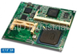
Kontron 18003-0000-26-1 CPU Board. AMD Geode GX1 | 266 MHz | Graphic | Sound | Ethernet | LVDS
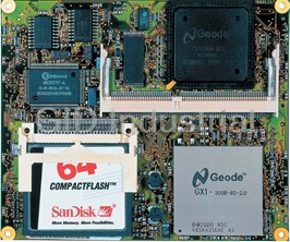
Kontron ETX-mgx 18003-0000-30-1 CPU Board with AMD Geode GX1 300 MHz processor, graphic, sound, Ethe...

Kontron 18003-0000-99-2 Accessory - KONTRON 18003-0000-99-2 Heatspreader is for the ETX-mgx

Kontron 18007-0000-10-3 CPU Board. ETX-P3m 10000 Intel Celeron 1.0 GHz (socket)
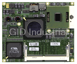
Kontron HSP-P3m ETX Single Board Computer - Intel Pentium III M/Celeron Support, Audio, Video, Seria...
Request a Quote

The quote request has been received
Close

Facing challenges or have inquiries? Feel free to contact us!
Call Us +1-469-283-2440
What they say about us
FANTASTIC RESOURCE
One of our top priorities is maintaining our business with precision, and we are constantly looking for affiliates that can help us achieve our goal. With the aid of GID Industrial, our obsolete product management has never been more efficient. They have been a great resource to our company, and have quickly become a go-to supplier on our list!
Bucher Emhart Glass
EXCELLENT SERVICE
With our strict fundamentals and high expectations, we were surprised when we came across GID Industrial and their competitive pricing. When we approached them with our issue, they were incredibly confident in being able to provide us with a seamless solution at the best price for us. GID Industrial quickly understood our needs and provided us with excellent service, as well as fully tested product to ensure what we received would be the right fit for our company.
Fuji
HARD TO FIND A BETTER PROVIDER
Our company provides services to aid in the manufacture of technological products, such as semiconductors and flat panel displays, and often searching for distributors of obsolete product we require can waste time and money. Finding GID Industrial proved to be a great asset to our company, with cost effective solutions and superior knowledge on all of their materials, it’d be hard to find a better provider of obsolete or hard to find products.
Applied Materials
CONSISTENTLY DELIVERS QUALITY SOLUTIONS
Over the years, the equipment used in our company becomes discontinued, but they’re still of great use to us and our customers. Once these products are no longer available through the manufacturer, finding a reliable, quick supplier is a necessity, and luckily for us, GID Industrial has provided the most trustworthy, quality solutions to our obsolete component needs.
Nidec Vamco
TERRIFIC RESOURCE
This company has been a terrific help to us (I work for Trican Well Service) in sourcing the Micron Ram Memory we needed for our Siemens computers. Great service! And great pricing! I know when the product is shipping and when it will arrive, all the way through the ordering process.
Trican Well Service
GO TO SOURCE
When I can't find an obsolete part, I first call GID and they'll come up with my parts every time. Great customer service and follow up as well. Scott emails me from time to time to touch base and see if we're having trouble finding something.....which is often with our 25 yr old equipment.
ConAgra Foods