

 Manufacturers
KEPCO RTW5-10KC

Description
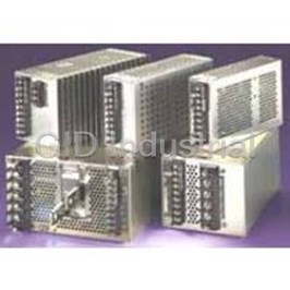
Kepco RTW5-10KC Power Supply with Enclosure
Part Number
RTW5-10KC
Price
Request Quote
Manufacturer
KEPCO
Lead Time
Request Quote
Category
PRODUCTS - R
Specifications
INPUT CURRENT
0.7A rms max. (100-120 Va-c input, 100% load); 0.4A rms max. (200-240 Va-c input, 100% load). 3.3V model: 0.6A rms max. (100-120 Va-c input, 100% load); 0.3A rms max. (200-240 Va-c input, 100% load).
INPUT PROTECTION AND SOFT START
A thermistor circuit reduces start-up surge. Units are protected against shorts by an input fuse. Fuse value 2A, 250V (Wickmann P/N C1-372-2.0A, Kepco P/N 541-0136).
INPUT SOURCE FREQUENCY
Nominal 50/60 Hz; Range 47-440 Hz (0 to 100% load, -10 to 71°C). (At 440 Hz the leakage current exceeds the VDE safety specification limit.)
INPUT SURGE
cold start 25 °C (First surge only, not including the current flow into the EMI filter) 14A typ. (100 V a-c, 100% load); 28A typ. (200 Va-c, 100% load)
INPUT VOLTAGE
Nominal 100-120V a-c, 220-240V a-c, range: 85-265V a-c (0 to 100% load, -10 to 71°C); d-c range: 120 -370V d-c; polarity insensitive. Safety agency approval applies only to a-c input operation.
Datasheet


Extracted Text
INSTRUCTION MANUAL An ISO 9001 Company. KEPCO RTW 50 WATT SINGLE OUTPUT, PFC, 50W OPEN FRAME POWER SUPPLIES I INTRODUCTION SCOPE OF MANUAL. This instruction manual covers the installation and operation of the Kepco RTW 50W Series of Open Frame PFC (Power Factor Corrected) RoHS (Reduction of Hazardous Substances) compliant Switching Power Supplies. DESCRIPTION. The Kepco RTW 50W Series consists of seven models of switching power supplies, with a single output as shown in Table 1. Units may be operated with a nominal 100 to 120V a-c and 220 to 240V a-c (input voltage range 85 to 265 Va-c), 50-60 Hz (input frequency range 47-440Hz.). They will also operate on 120V to 370V d-c input. The RTW 50W Series employs a forward converter with a fixed switching frequency of 190KHz. Power Factor Correction (PFC) is provided by a boost converter. Regulation is provided by pulse width modulation. A thermistor circuit prevents excessive turn-on current surge. Remote on-off and remote programming of output voltage using an external resis- tance can be implemented. Overvoltage and overcurrent protection is provided. Current limiting with automatic recovery from short circuit is featured. Units are convection cooled L-chassis construction. Models with a factory-installed steel cover are indicated by a C suffix following the model number (e.g., RTW 5-10KC). Section II contains specifications and operating limits of individual RTW 50W Series models (Table 1) as well as specifications and operating limits common to all RTW 50W Series Models. Section III describes installation and Section IV describes operation II SPECIFICATIONS The following specifications are at rated input voltages at 25°C unless otherwise specified. TABLE 1. OUTPUT RATINGS AND SPECIFICATIONS, RTW 50W SERIES (6) RTW 3.3-12K RTW 5-10K RTW 12-4.3K RTW 15-3.5K RTW 24-2.2K RTW 28-1.8K RTW 48-1.1K MODEL OUTPUT VOLTAGE SETTING, d-c 3.3 ±0.03V 5 ±0.05V 12 ±0.12V 15 ±0.15V 24 ±0.24V 28 ±0.28V 48 ±0.48V ADJUSTMENT RANGE, Vd-c 2.60-4.0 4.0-5.8 9.6-13.2 12-16.5 19.2-26.4 22.4-30.8 38.4-52.8 OUTPUT CURRENT, MAX (AMPS) 12.5 10 4.3 3.5 2.2 1.8 1.1 (3) OUTPUT POWER, MAX (WATTS) 41.2 50 51.6 52.5 52.8 50.4 52.8 (1) 4.2-5.2 6.0-6.9 13.7-15.7 17.0-19.0 27.0-30.5 32.0-35.0 55.0-60.0 OVP SETTING (VOLTS) (2) OVERCURRENT SETTING 10.5-12.5 10.5-12.5 4.5-5.4 3.68-4.38 2.3-2.75 1.9-2.25 1.15-1.38 (AMPERES) SHORT CIRCUIT CURRENT 15.5 13 5.6 4.5 3.0 2.5 1.7 (AMPERES) (typ) 100 Va-c 75% 80% 81% 82% 82% 82% 82% EFFICIENCY 200 Va-c 77% 82% 83% 85% 85% 85% 85% RIPPLE AND Switching ripple (typ) 80 80 100 100 150 150 200 (4) NOISE (4) (mV p-p) spike noise (typ) 120 120 150 150 200 200 300 (5) 250 Ohms 250 Ohms 500 Ohms 500 Ohms 1K Ohms 1K Ohms 2K Ohms External Potentiometer (1) An overvoltage shuts down the output. Recover by recycling a-c input (30 second delay required before resetting). (2) Square type. After the cause of overcurrent is removed, output voltage recovers automatically. (3) See Figure 2 for temperature and input voltage rating. (4) Bandwidth 100MHz. Ripple and noise will be approximately 1.5 times these values in the operating temperature range -10 ~ 0°C. The ripple and noise values tabulated are valid when the output is derated as shown in figure 2 from 40 ~ 71°C. (5) Used for remote programming of output voltage. See Section IV OPERATION, REMOTE VOLTAGE PROGRAMMING. (6) Specifications are identical for models either K or KC suffix INPUT VOLTAGE: Nominal 100-120V a-c, 220-240V a-c, range: 85-265V a-c (0 to 100% load, -10 to 71°C); d-c range: 120 -370V d-c; polarity insensitive. Safety agency approval applies only to a-c input operation. INPUT SOURCE FREQUENCY: Nominal 50/60 Hz; Range 47-440 Hz (0 to 100% load, -10 to 71°C). (At 440 Hz the leakage current exceeds the VDE safety specification limit.) INPUT CURRENT: 0.7A rms max. (100-120 Va-c input, 100% load); 0.4A rms max. (200-240 Va-c input, 100% load). 3.3V model: 0.6A rms max. (100-120 Va-c input, 100% load); 0.3A rms max. (200-240 Va-c input, 100% load). INPUT PROTECTION AND SOFT START: A thermistor circuit reduces start-up surge. Units are protected against shorts by an input fuse. Fuse value 2A, 250V (Wickmann P/N C1-372-2.0A, Kepco P/N 541-0136). INPUT SURGE: cold start 25 °C (First surge only, not including the current flow into the EMI filter) 14A typ. (100 V a-c, 100% load); 28A typ. (200 Va-c, 100% load). KEPCO, INC. � 131-38 SANFORD AVENUE � FLUSHING, NY. 11355 U.S.A. � TEL (718) 461-7000 � FAX (718) 767-1102 http://www.kepcopower.com � email: hq@kepcopower.com ©2010, KEPCO, INC 1 Data subject to change without notice 228-1510 REV 6 LEAKAGE CURRENT: WEIGHT: 8.82 oz. (250 grams) max 0.28mA typ, 0.45mA max at 120V a-c and 60 Hz (in conformance with Den-An), WARRANTY: One year. 0.38mA typ, 0.6mA max at 240V d-c and 60 Hz (in conformance with IEC 950 and UL1950). POWER FACTOR: 0.99 typ. at 100 Va-c, 0.94 typ. at 200 Va-c. STABILIZATION: Source Effect: (85 to 132Va-c, 170-265 Va-c) 0.1% typ., 0.2% max. Load Effect: (0% - 100% of rated output current) 0.2% typ., 0.4% max. Temperature effect: (-10 to 71°C) 0.5% typ., 1.0% max. Combined effect (source, load, temperature): 0.9% typ., 1.8% max. Time effect (drift): (1/2 to 8 hr. at 25°C) 0.2% typ., 0.5% max. TRANSIENT RECOVERY: A step load change from 50% to 100% of rated output current in 50 microseconds or more, produces no more than 4% output voltage excur- sion. Recovery time is 1ms maximum. ACCEPTABLE LOAD CAPACITANCE: 10,000µF max (start-up time is affected) OUTPUT HOLDING TIME: Upon input interruption, output maintained for 30ms typ. (20ms min.). 3.3V model: 55ms typ., 40ms min. 28V model: 35ms typ., 25ms min. START UP TIME: 400ms typ., 500ms max. at 100 Va-c; 200ms typ., 300ms max., at 240 Va-c. Between 0 and -20° C output may take 3 seconds to stabilize. OVERVOLTAGE PROTECTION: Fixed, factory set. See Table 1. The overvoltage circuit is set by Zener diode clamp, latching will occur. FIGURE 1. OUTPUT POWER VS. OVERCURRENT: Square type, output voltage returns to rated level upon removal TEMPERATURE, of cause of malfunction. K MODELS (WITHOUT COVER) OPERATING TEMPERATURE: -10 to 71°C (start up -20 to -10°C). See the der- ating, Figure 1 or 2. Do not allow the power supply to become dust covered because that will decrease the cooling efficiency of the unit and cause insulation to deteriorate. STORAGE TEMPERATURE: -30°C to + 75°C. COOLING: Natural convection. ORIENTATION: Vertical or horizontal (see Figure 5). HUMIDITY: Operating: 10% to 95% relative humidity, storage:10% to 95% relative humidity; noncondensing, wet bulb temperature < or = 35°C. WITHSTANDING VOLTAGE (at 15 to 35°C ambient, 10 to 85% relative humidity): Between input and output terminals, 3.0 KV a-c for 1 minute, cutout current 10 ma. Between input terminals and ground, 2.0 KV a-c for 1 minute, cutout current 10 ma. Between output terminals and ground, 500V a-c for 1 minute, cutout current 20 ma. INSULATION RESISTANCE: Between input and output, input and ground, output and ground, ±RC terminals and output, ±RC terminals and input: 100 megohms minimum (500V d-c, 15 to 35°C ambient, 10 to 85% relative humidity). VIBRATION: Three axes, one hour each, sweep time 10 min:, nonoperating 5-10 Hz., 10 mm amplitude. FIGURE 2. OUTPUT POWER VS. 2 10-200 Hz., 2G (19.6m/S ) acceleration. TEMPERATURE, 2 KC MODELS (WITH COVER) SHOCK: Three axes, 20G (196m/S ) when installed per Figure 5, method A; 60G 2 (588m/S ) when installed per Figure 5, method B or C, 11ms ±5 msec pulse dura- tion, three shocks each axis, nonoperating, 1/2 sine pulse. EMC - EMISSIONS: Radiated Noise 30MHZ to 1GHz: FCC Class B, VCCI-B, EN55011-B, EN55022-B Conducted Noise 0.15MHz to 30MHz: FCC Class B, VCCI-B, EN55011-B, EN55022-B Input Harmonics (on AC Mains) 0 to 2KHZ: EN 61000-3-2. EMC - IMMUNITY: Designed to meet EN 50082-2. ESD: EN 61000-4-2 Level 4, Normal operation. Radiated Field Noise: EN 61000-4-3 Level 3, Normal operation. Electrical Fast Transient/Burst (EFT): EN 61000-4-4 Level 3, Normal operation. Surge: EN 61000-4-5 Level 4, no damage. Conducted Noise: EN 61000-4-6 Level 3, Normal operation. FIGURE 3. COMPONENT LOCATIONS Power Frequency Magnetic Field: EN 61000-4-8 Level 4, Normal operation. Voltage Dips, Short Interruptions, Voltage Variation: EN 61000-4-11, Normal operation. SAFETY: All units designed to meet EN 60950:2001 Assistance for DEN-AN. U.S. UL 60950 First Edition.; Canada: CSA-22.2 No. 60950-1. (ambient temp. 50°C max.). RTW 50W units are CE marked per the Low Voltage Directive (LVD), EN60950 73/23/EEC AND 93/68/EEC. [The standards do not apply with DC input operation.] KEPCO, INC. � 131-38 SANFORD AVENUE � FLUSHING, NY. 11355 U.S.A. � TEL (718) 461-7000 � FAX (718) 767-1102 http://www.kepcopower.com � email: hq@kepcopower.com 2 228-1510 REV 6 051010 III INSTALLATION MOUNTING THE POWER SUPPLY: Refer to Figures 5 and 6. The unit may be mounted on one mounting surface. Note the restrictions for maximum penetration of mounting screws. The air temperature surrounding the power supply must not exceed the ambient values given in the graph in Figure 1. CONNECTIONS: Connect the load to the power supply as shown in Figure 4A, B or C. The unit is shipped with shorting links in place for Local sensing. The AC input power is applied via the terminal block. Make sure to connect the AC input Neutral, Line and Ground wires to the respective terminals of the terminal block (see Figure 3). Sensing (either Local or Remote) MUST be used. LOCAL/REMOTE SENSING: Figure 4C shows proper connection of multiple loads using either remote or local sensing. If local or remote sensing is not configured, the unit will not work properly. The unit is shipped with shorting links in place for Local sensing. For remote sensing, remove the shorting links and connect the +S and S terminals to the load. Remote sensing compensation is up to 0.4V per load wire (0.15V for RTW 3.3-12K, 0.25V for RTW 5-10K). Transient recovery specs may not be met when remote sensing is used. If oscil- lations set off overvoltage protection, install one electrolytic capacitor (470mF min) between +S and + and one between and S terminals. IV OPERATION When output voltage is available, the green LED is on. The Output Voltage Adjust trimmer (see Figure 3) allows adjustment of the output voltage within the range specified in Table 1. REMOTE ON OFF: Use ±RC terminals to set output on or off after setting the Remote On/Off switch to Y (see Figure 3). Output OFF requires no voltage, or short circuit, or 0 to 0.8V across ±RC terminals; Output ON requires 4.5 to 12.5V (or 12.5 to 24.5V through 1.5K Ohms) across ±RC terminals. ±RC terminals are isolated from AC input and DC output terminals. REMOTE VOLTAGE PROGRAMMING: In addition to the integral trimmer, output voltage can be also be adjusted via an external vari- able resistance (see Figure 4B). The variable resistance specified in Table 1 must be substituted for the shorting link between + and +S ter- minals. Note that load effect for RTW 50W is increased using this technique, and may exceed values listed above under STABILIZATION. SERIES OPERATION: When a number of power supplies are operating in series, the current rating is to be limited to the rating of the power supply with the lowest rating. A diode (Vr>2Σ Vo, If>2Io, Vf<< low) must be connected to the power supply output terminals to protect the unit from reverse voltage. A B C D FIGURE 4. LOAD CONNECTIONS KEPCO, INC. � 131-38 SANFORD AVENUE � FLUSHING, NY. 11355 U.S.A. � TEL (718) 461-7000 � FAX (718) 767-1102 http://www.kepcopower.com � email: hq@kepcopower.com 051010 228-1510 REV 6 3 FIGURE 5. POWER SUPPLY MOUNTING FIGURE 6. RTW 50W K MODELS (WITHOUT COVER) MECHANICAL OUTLINE DIAGRAM FIGURE 7. RTW 50W KC MODELS (WITH COVER) MECHANICAL OUTLINE DIAGRAM KEPCO, INC. � 131-38 SANFORD AVENUE � FLUSHING, NY. 11355 U.S.A. � TEL (718) 461-7000 � FAX (718) 767-1102 http://www.kepcopower.com � email: hq@kepcopower.com 4 228-1510 REV 6 051010
Frequently asked questions
What makes Elite.Parts unique?

What kind of warranty will the RTW5-10KC have?
Which carriers does Elite.Parts work with?
Will Elite.Parts sell to me even though I live outside the USA?
I have a preferred payment method. Will Elite.Parts accept it?
Why buy from GID?

Quality
We are industry veterans who take pride in our work

Protection
Avoid the dangers of risky trading in the gray market

Access
Our network of suppliers is ready and at your disposal

Savings
Maintain legacy systems to prevent costly downtime

Speed
Time is of the essence, and we are respectful of yours
Related Products
KEPCO-RAX 12-25K-300 Watt Single Output Module Din Rail Mountable
KEPCO-RAX 15-20K-300 Watt Single Output Module Din Rail Mountable
KEPCO-RAX 28-10K-300 Watt Single Output Module Din Rail Mountable
KEPCO-RAX 28-6.2K-175 Watt Single Output Module Din Rail Mountable


Request a Quote

The quote request has been received

Close

Facing challenges or have inquiries? Feel free to contact us!
Call Us +1-469-283-2440
What they say about us
FANTASTIC RESOURCE
One of our top priorities is maintaining our business with precision, and we are constantly looking for affiliates that can help us achieve our goal. With the aid of GID Industrial, our obsolete product management has never been more efficient. They have been a great resource to our company, and have quickly become a go-to supplier on our list!
Bucher Emhart Glass
EXCELLENT SERVICE
With our strict fundamentals and high expectations, we were surprised when we came across GID Industrial and their competitive pricing. When we approached them with our issue, they were incredibly confident in being able to provide us with a seamless solution at the best price for us. GID Industrial quickly understood our needs and provided us with excellent service, as well as fully tested product to ensure what we received would be the right fit for our company.
Fuji
HARD TO FIND A BETTER PROVIDER
Our company provides services to aid in the manufacture of technological products, such as semiconductors and flat panel displays, and often searching for distributors of obsolete product we require can waste time and money. Finding GID Industrial proved to be a great asset to our company, with cost effective solutions and superior knowledge on all of their materials, it’d be hard to find a better provider of obsolete or hard to find products.
Applied Materials
CONSISTENTLY DELIVERS QUALITY SOLUTIONS
Over the years, the equipment used in our company becomes discontinued, but they’re still of great use to us and our customers. Once these products are no longer available through the manufacturer, finding a reliable, quick supplier is a necessity, and luckily for us, GID Industrial has provided the most trustworthy, quality solutions to our obsolete component needs.
Nidec Vamco
TERRIFIC RESOURCE
This company has been a terrific help to us (I work for Trican Well Service) in sourcing the Micron Ram Memory we needed for our Siemens computers. Great service! And great pricing! I know when the product is shipping and when it will arrive, all the way through the ordering process.
Trican Well Service
GO TO SOURCE
When I can't find an obsolete part, I first call GID and they'll come up with my parts every time. Great customer service and follow up as well. Scott emails me from time to time to touch base and see if we're having trouble finding something.....which is often with our 25 yr old equipment.
ConAgra Foods