

 Manufacturers
ISTARUSA IS-400R8P
Description
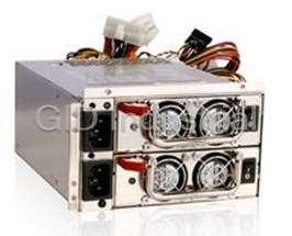
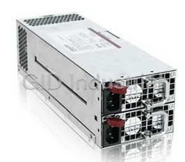
I-Star USA IS-400R8P Power Supply, 400W PS2 Mini Redundant Power Supply
Part Number
IS-400R8P
Price
Request Quote
Manufacturer
ISTARUSA
Lead Time
Request Quote
Category
PRODUCTS - I
Features
- Automatic Thermal Control (reduce Fan Speed)
- Backward Compatibility, -5V Available
- Efficiency: 74% at full load
- Industrial DIN-Connector for Reliability
- Industrial Japanese Components 40 deg.C
- OPP (Over Power Protection)
- OVP (Over Voltage Protection)
- Power Failure Alarm & Signals
- Remote Sensor on +5v & +3.3V
- Universal Input, Active PFC
Datasheet

Extracted Text
iStarUSA IS-400R8P IS -400R8P Redundant Switching Power Supply ( 4U- 400W+400W ) SPECIFICATION Revision: 1.0 727 , . Phillips Drive City of Industry. CA 91748. USA http:// www.istarusa.com TEL: 626-3038885 FAX: 626-3010588 TABLE OF CONTENTS 1. General..................................................................................................... 3 2. AC Input Specifications .......................................................................... 3 2.1 AC INPUT VOLTAGE, FREQUENCY AND CURRENT ( RATING: 100V-240VAC, 47-63HZ, 8-4A................ 3 2.2 AC INRUSH CURRENT ........................................................................................................... 3 2.3 INPUT POWER FACTOR CORRECTION ( ACTIVE PFC) ............................................................. 3 2.4 INPUT CURRENT HARMONICS ................................................................................................ 3 2.5 AC LINE DROPOUT ............................................................................................................... 3 3. DC Output Specification ......................................................................... 4 3.1 OUTPUT CURRENT / LOADING................................................................................................ 4 3.2 DC VOLTAGE REGULATION, RIPPLE AND NOISE ..................................................................... 4 3.3 TIMING REQUIREMENTS ........................................................................................................ 6 3.4 REMOTE ON/OFF CONTROL : PSON# ................................................................................... 6 3.5 EFFICIENCY .......................................................................................................................... 6 3.6 +5VSB (STANDBY) ............................................................................................................... 6 4. Protection ................................................................................................ 6 4.1 OVER POWER PROTECTION .................................................................................................. 7 4.2 OVER VOLTAGE PROTECTION................................................................................................ 7 4.3 OVER CURRENT PROTECTION................................................................................................ 7 4.3 SHORT CIRCUIT PROTECTION ................................................................................................ 7 5. Environmental Requirements ................................................................ 7 5.1 TEMPERATURE ..................................................................................................................... 7 5.2 HUMIDITY ............................................................................................................................. 7 6. Agency Requirements ............................................................................ 8 6.1 SAFETY CERTIFICATION. ....................................................................................................... 8 6.2 AC INPUT LEAKAGE CURRENT ............................................................................................... 8 7. Redundant Power Supply Function....................................................... 8 7.1 REDUNDANCY....................................................................................................................... 8 7.2 HOT SWAP REQUIREMENTS .................................................................................................. 8 7.3 LED INDICATORS ................................................................................................................. 8 8. Reliability ................................................................................................. 8 8.1 MEAN TIME BETWEEN FAILURES (MTBF) .............................................................................. 9 9. Physical Characteristics Size ................................................................10 9.1 POWER SUPPLY DIMENSION: 150 MM(W) X 85 MM(H) X 199 MM(D) ........................................10 2 1. General This is the specification of Model IS-400R8P; it is intended to describe the functions and performance of the subject power supply. This 400 watts Redundant Power Supply with Active PFC (Power Factor Correction) capability, meets EN61000-3-2 and equips Full Range Input features. 2. AC Input Specifications 2.1 AC Input Voltage, Frequency and Current ( Rating: 100V-240Vac, 47-63Hz, 8-4A ) The power supply must operate within all specified limits over the input voltage range in Table 1. Harmonics distortion of up to 10% THD must not cause the power supply to go out of specified limits. Parameter Minimum Norminal Maximum Max. Current Voltage (115V) 90 Vac 100-120Vac 132 Vac 8A Voltage (230V) 180Vac 200-240Vac 264 Vac 4A Frequency 47 Hz 50 / 60 Hz 63 Hz Table 1 – AC Input Voltage and Frequency 2.2 AC Inrush Current The power supply must meets inrush requirements of any rated AC voltage, during turn on at any phase of voltage, during a single cycle AC dropout condition, during repetitive On/Off cycling of AC, and over the specified temperature range. The peak inrush current shall be less than the rating of its critical components (including input fuse, bulk rectifiers, and surge limiting device). 2.3 Input Power Factor Correction ( Active PFC) The power factor at full load shall be ≥ 0.95 at nominal input voltage. 2.4 Input Current Harmonics When the power supply is operated in 90-264Vac of Sec. 2.1, the input harmonic current drawn on the power line shall not exceed the limits set by EN61000-3-2 class “D” standards. The power supply shall incorporate universal power input with active power factor correction. 2.5 AC Line Dropout An AC line dropout of 17mS or less shall not cause any tripping of control signals or protection circuits. If the AC dropout lasts longer than 17mS the power supply should recover and meet all turn on requirements. The power supply shall meet the regulation requirement over all rated AC voltages, frequencies, and output loading conditions. Any dropout of the AC line shall not cause damage to the power supply. An AC line dropout is defined as a drop in AC line to 0VAC at any phase of the AC line for any length of time. 3 3. DC Output Specification 3.1 Output Current / Loading The following table defines power and current rating. The power supply shall meet both static and dynamic voltage regulation requirements for minimum load condition. Output +5V +3.3V +12V -5V -12V +5VSB Voltage Max. Load 24A 24A 30A 0.5A 1A 2A Min. Load 2A 1A 2A 0A 0A 0.1A Max. Combined 150W Total Output 380W 2.5W 12W 10W Table 2– Output Loads Range 1: Note 1: Maximum continuous total DC output power should not exceed 400 W. 3.2 DC Voltage Regulation, Ripple and Noise The power supply output voltages must stay within the following voltage limits when operating at steady state and dynamic loading conditions. All outputs are measured with reference to the return remote sense (ReturnS) signal. The +5V,+3.3V, +12V, -5V,-12V and +5VSB outputs are measure at the power supply connectors references to ReturnS. The +5V and +3.3V is measured at its remote sense signal (+5VS, +3.3VS) located at the signal connector. Output Voltage +5V +3.3V +12V -5V -12V +5VSB Load Reg. +/-5% +/-5% +/-5% +/-10% +/-5% +/-5% ±1% Line Reg. ±1% ±1% ±1% ±1% ±1% Ripple & Noise 50mV 50mV 120mV 100mV 120mV 50mV Table 3 – Regulation, ripple and noise Ripple and Noise shall be measured using the following methods: a) Measurements made differentially to eliminate common-mode noise b) Ground lead length of oscilloscope probe shall be 0.25 inch. c) Measurements made where the cable connectors attach to the load. d) Outputs bypassed at the point of measurement with a parallel combination of 10uF tantalum capacitor in parallel with a 0.1uF ceramic capacitors. e) Oscilloscope bandwidth of 0 Hz to 20MHz. f) Measurements measured at locations where remote sense wires are connected. g) Regulation tolerance shall include temperature change, warm up drift and dynamic load 3.3 Timing Requirements These are the timing requirements for the power assembly operation. The output voltages must rise from 10% to within regulation limits (Tvout_rise) within 5 to 70mS. The +5V, +3.3V and +12V output voltages should start to rise at about the same time. All outputs must rise monotonically. The +5V output needs to be greater than the +3.3V output during any point of the voltage rise. The +5V output must never be greater than the +3.3V output by more than 2.25V. Each output voltage shall reach regulation within 50 mS (Tvout_on) of each other during turn on of the power supply. Each output voltage shall fall out of regulation within 400 mS (Tvout_off) of each other during turn off. Figure 1 and figure 2 show the turn On and turn Off timing requirement. In Figure 2, the timing is shown with both AC and 4 PSON# controlling the On/Off of the power supply. Item Description MIN MAX Units Tsb_on-delay Delay from AC being applied to +5VSB being within 1500 mS regulation. Tac_on-delay Delay from AC being applied to all output voltages being 2500 mS within regulation. Tvout_holdup All main output voltage stay within regulation after loss of 18 mS AC Tpwok_holdup Delay from loss of AC deassertion of PWOK. 17 mS Tpson_on_delay Delay from PSON# active to output voltage within 5 400 mS regulation limits. Tpson_pwok Delay from PSON# deactive to PWOK being deasserted. 50 mS Tpwok_on Delay from output voltage within regulation limits to PWOK 100 500 mS asserted at turn on. Tpwok_off Delay from PWOK deasserted to output voltages (+5V, 1 mS +3.3V, +12V) dropping out of regulation limits. Tpwok_low Duration of PWOK being in the deasserted state during an 100 mS off/on cycle using AC or the PSON# signal. . Tsb_vout Delay from +5VSB being in regulation to O/Ps being in 50 1000 mS regulation at AC turn on. Item Description MIN MAX Units Tvout_rise Output voltage rise time from each main output.(+5Vsb < 5 70 mS 70mS) Tvout_on All main output must be within regulation of each other 50 mS within this time. Tvout_off All main output must leave regulation within this time 400 mS Table 4 – Output Voltage Timing Vout V1 10% Vout V2 V3 V4 Tvout_on Tvout_off Tvout_rise Figure 1 : Output Voltage Timing Table 5 – Turn On/Off Timing 5 AC Input AC Off AC On Tvout_holdup Vout Tac_on-delay Tpwok_low Tsb_on-delay Tpwok_off Tpwok_off PWOK Tpwok_on Tpwok_holdup Tsb_on-delay Tpwok_on Tpson_pwok +5VSB Tsb_vout Tsb_holdup Min.>70mS Tpson_on_delay PSON# AC turn 0n/off cycle PSON turn on/off cycle Figure 2 : Turn On/Off Timing 3.4 Remote On/Off Control : PSON# The PSON# signal is required to remotely turn on/off the power supply. PSON# is an active low signal that turns on the +5V, +3.3V, +12V,-5V and –12V power rails. When this signal is not pulled low by the system, or left open, the outputs (except the +5VSB and V bias) turn off. This signal is pulled to a standby voltage by a pull-up resistor internal to the power supply. Signal Type Accepts an open collector/drain input from the system. Pull-up to VSB located in power supply. PSON# = Low Power ON PSON# = High Power OFF Table 6 – PWOK Signal Characteristic 3.5 Efficiency The efficiency is ʁ 74% at full loading condition to help reduce system power consumption at typical system loading conditions. . 3.6 +5VSB (Standby) The +5VSB output is always on (+5V Standby) when AC power is applied and power switch is turned on. The +5VSB line is capable of delivering at a maximum of 2A for PC board circuit to operate. 4. Protection Protection circuits inside the power supply shall cause only the power supply’s main outputs to shutdown. If the power supply latches off due to a protection circuit tripping, either a AC cycle OFF for 15 sec, or PSON# cycle HIGH for 1 sec must be able to restart the power supply. 6 4.1 Over Power Protection The OPP function shall work at 130%~270% of rating of output power, then all outputs shut down in a latch off mode. The latch shall be cleared by toggling the PSON# signal or by cycling the AC power. The power supply shall not be damaged from repeated power cycling in this condition. If only one module works inside the power supply, the OPP is at 110%~170% of rating of power supply. 4.2 Over Voltage Protection Each hot swap module has respective OVP circuit. Once any power supply module shut down in a latch off mode while the output voltage exceeds the over voltage limit shown in Table 7, the other modules should deliver the sufficient power to the device continually. Voltage Minimum Maximum Shutdown Mode +5V +5.7V +6.5V Latch Off +3.3V +3.9V +4.5V Latch Off +12V +13.3V +14.5V Latch Off 5VSB +5.7V +6.5V Auto recovery Table 7 –Over Voltage protection 4.3 Over Current Protection The power supply should contain the OCP function on each hot swap module. The power supply should be shut down in a latch off mode while the respective output current exceeds the limit as shown in Table 8. When the latch has been cleared by toggling the PSON# single or cycling the AC input power. The power supply module should not be damaged in this condition. Voltage Minimum Maximum Shutdown Mode +5V 110% 160% Latch Off +3.3V 110% 160% Latch Off +12V 110% 160% Latch Off Table 8 –Over Current protection 4.4 Short Circuit Protection The power supply shall shut down in a latch off mode when the output voltage is short circuit. 5. Environmental Requirements 5.1 Temperature Operating Temperature Range: 0°C ~ 50°C (32°F~ 104°F) Non-Operating Temperature Range: -40°C ~ 70°C (-40°F~ 158°F) 5.2 Humidity Operating Humidity Range: 20% ~ 90%RH non-condensing Non-Operating Humidity Range: 5% ~ 95%RH non-condensing 7 6. Agency Requirements 6.1 Safety Certification. rd Product Safety: UL 60950-1 2000Edition, IEC60950-1, 3 Edition EU Low Voltage Directive (73/23/EEC) (CB) TÜV RFI Emission: FCC Part15 ( Radiated & Conducted Emissions ) rd CISPR 22,3 Edition / EN55022: 1998 + A1: 2000) EN61000-3-2:2000 PFC Harmonic: EN61000-3-3: 1995 + A1: 2002 Flicker: EN55024: 1998 + A1: 2001 and A2: 2003 Immunity against: -IEC 61000-4-2 -Electrostatic discharge: -IEC 61000-4-3 -Radiated field strength: -IEC 61000-4-4 -Fast transients: -IEC 61000-4-5 -Surge voltage: -IEC 61000-4-6 -RF Conducted -IEC 61000-4-11 -Voltage Dips and Interruptions Table 8 –Safety Certification 6.2 AC Input Leakage Current Input leakage current from line to ground will be less than 3.5mA rms. Measurement will be made at 240 VAC and 60Hz. 7. Redundant Power Supply Function 7.1 Redundancy The redundant power supply is N+1=N (400W+400W=400W) function power supply, each one module is redundancy when any one module was failed. To be redundant each item must be in the Hot swap power supply module. 7.2 Hot Swap Requirements The redundant power supply modules shall be hot swappable. Hot swapping a power supply is the process of inserting and extracting a power supply from an operating. During this process the output voltage shall remain within the limits specified in Table 7 with the capacitive load specified Table 9. The Sub-system shall not exceed the maximum inrush current as specified in section 2.2. The power supply can be hot swapped by the following methods: AC connecting separately to each module. Up to two power supplies may be on a single AC power source. Extraction: The AC power will be disconnected from the power supply first and then the power supply is extracted from the sub-system. This could occur in standby mode or powered on mode. Insertion: The module is inserted into the cage and then AC power will be connected to the power supply module. 8 For power modules with AC docking at the same time as DC. Extraction: The module is extracted from the cage and both AC and DC disconnect at the same Time. This could occur in standby or power on mode. No damage or arcing shall occur to the DC or AC contacts which could cause damage. Insertion: The AC and DC connect at the same time as the module is inserted into the cage. No damage to the connector contacts shall occur. The module may power on or come up into standby mode. Many variations of the above are possible. Supplies need to be compatible with these different variations depending upon the sub-system construction. In general, a failed (off by internal latch or external control) supply may be removed, then replaced with a good power supply(must use the same model) , however, hot swap needs to work with operational as well as failed power supplies. The newly inserted power supply may get turned on by inserting the supply into the system or by system management recognizing an inserted supply and explicitly turning it on. 7.3 LED Indicators There shell be a single bi-color LED. The GREEN LED shall turn ON to indicate that all the power outputs are available. The Red LED shall turn ON to indicate that the power supply has failed, shutdown due to over current, or shutdown due to component failure.The LED(s) shall be visible on the power supply’s exterior face. The LED location shall meet ESD requirements. LED shall be securely mounted in such a way that incidental pressure on the LED shall not cause it to become displaced. 8. Reliability 8.1 Mean Time Between Failures (MTBF) The MTBF of the power supply shall be calculated utilizing the Part-Stress Analysis method of MIL217F or Bell core RPP. The calculated MTBF of the power supply shall be greater than 100,000 hours under the following conditions: Full rated load 120V AC input Ground Benign 25°C Technical information in this specification is subject to change without notice. The revision of specification will be marked on the cover. 9 9. Physical Characteristics Size 9.1 Power Supply Dimension: 150mm(W) x 85mm(H) x 199 mm(D) Mechanical drawing: 10
Frequently asked questions
What makes Elite.Parts unique?

What kind of warranty will the IS-400R8P have?
Which carriers does Elite.Parts work with?
Will Elite.Parts sell to me even though I live outside the USA?
I have a preferred payment method. Will Elite.Parts accept it?


What they say about us
FANTASTIC RESOURCE
One of our top priorities is maintaining our business with precision, and we are constantly looking for affiliates that can help us achieve our goal. With the aid of GID Industrial, our obsolete product management has never been more efficient. They have been a great resource to our company, and have quickly become a go-to supplier on our list!
Bucher Emhart Glass
EXCELLENT SERVICE
With our strict fundamentals and high expectations, we were surprised when we came across GID Industrial and their competitive pricing. When we approached them with our issue, they were incredibly confident in being able to provide us with a seamless solution at the best price for us. GID Industrial quickly understood our needs and provided us with excellent service, as well as fully tested product to ensure what we received would be the right fit for our company.
Fuji
HARD TO FIND A BETTER PROVIDER
Our company provides services to aid in the manufacture of technological products, such as semiconductors and flat panel displays, and often searching for distributors of obsolete product we require can waste time and money. Finding GID Industrial proved to be a great asset to our company, with cost effective solutions and superior knowledge on all of their materials, it’d be hard to find a better provider of obsolete or hard to find products.
Applied Materials
CONSISTENTLY DELIVERS QUALITY SOLUTIONS
Over the years, the equipment used in our company becomes discontinued, but they’re still of great use to us and our customers. Once these products are no longer available through the manufacturer, finding a reliable, quick supplier is a necessity, and luckily for us, GID Industrial has provided the most trustworthy, quality solutions to our obsolete component needs.
Nidec Vamco
TERRIFIC RESOURCE
This company has been a terrific help to us (I work for Trican Well Service) in sourcing the Micron Ram Memory we needed for our Siemens computers. Great service! And great pricing! I know when the product is shipping and when it will arrive, all the way through the ordering process.
Trican Well Service
GO TO SOURCE
When I can't find an obsolete part, I first call GID and they'll come up with my parts every time. Great customer service and follow up as well. Scott emails me from time to time to touch base and see if we're having trouble finding something.....which is often with our 25 yr old equipment.
ConAgra Foods