

 Manufacturers
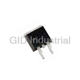
INTERNATIONAL RECTIFIER IRF7328TR

Description
HEXFET DUAL P 30V 8A SO-8
Part Number
IRF7328TR
Price
Request Quote
Manufacturer
INTERNATIONAL RECTIFIER
Lead Time
Request Quote
Category
PRODUCTS - I
Datasheet


Extracted Text
PD -94000 IRF7328 ® HEXFET Power MOSFET � Trench Technology V R max I DSS DS(on) D � Ultra Low On-Resistance -30V 21mΩ@V = -10V -8.0A GS � Dual P-Channel MOSFET 32mΩ@V = -4.5V -6.8A GS � Available in Tape & Reel Description 1 ® 8 New trench HEXFET Power MOSFETs from S1 D1 International Rectifier utilize advanced processing 2 7 G1 D1 techniques to achieve extremely low on-resistance 3 6 per silicon area. This benefit, combined with the S2 D2 ruggedized device design that HEXFET power 4 5 G2 D2 MOSFETs are well known for, provides the designer with an extremely efficient and reliable device for use SO-8 in battery and load management applications. Top V iew Absolute Maximum Ratings Parameter Max. Units V Drain-Source Voltage -30 V DS I @ T = 25°C Continuous Drain Current, V @ -10V -8.0 D A GS I @ T = 70°C Continuous Drain Current, V @ -10V -6.4 A D A GS I Pulsed Drain Current� -32 DM P @T = 25°C Maximum Power Dissipation� 2.0 W D A P @T = 70°C Maximum Power Dissipation� 1.3 W D A Linear Derating Factor 16 mW/°C V Gate-to-Source Voltage ± 20 V GS T , T Junction and Storage Temperature Range -55 to + 150 °C J STG Thermal Resistance Parameter Max. Units R Maximum Junction-to-Ambient � 62.5 °C/W θJA www.irf.com 1 10/04/00 IRF7328 Electrical Characteristics @ T = 25°C (unless otherwise specified) J Parameter Min. Typ. Max. Units Conditions V Drain-to-Source Breakdown Voltage -30 ––– ––– V V = 0V, I = -250μA (BR)DSS GS D ΔV /ΔT Breakdown Voltage Temp. Coefficient ––– -0.018 ––– V/°C Reference to 25°C, I = -1mA (BR)DSS J D ––– 17 21 V = -10V, I = -8.0A � GS D R Static Drain-to-Source On-Resistance DS(on) mΩ ––– 26.8 32 V = -4.5V, I = -6.8A � GS D V Gate Threshold Voltage -1.0 ––– -2.5 V V = V , I = -250μA GS(th) DS GS D g Forward Transconductance 12 ––– ––– S V = -10V, I = -8.0A fs DS D ––– ––– -15 V = -24V, V = 0V DS GS I Drain-to-Source Leakage Current DSS μA ––– ––– -25 V = -24V, V = 0V, T = 70°C DS GS J Gate-to-Source Forward Leakage ––– ––– -100 V = -20V GS I nA GSS Gate-to-Source Reverse Leakage ––– ––– 100 V = 20V GS Q Total Gate Charge ––– 52 78 I = -8.0A g D Q Gate-to-Source Charge ––– 9.8 ––– nC V = -15V gs DS Q Gate-to-Drain ("Miller") Charge ––– 8.3 ––– V = -10V gd GS t Turn-On Delay Time ––– 13 20 V = -15V, V = -10.0V d(on) DD GS t Rise Time ––– 15 23 I = -1.0A r D ns t Turn-Off Delay Time ––– 198 297 R = 6.0Ω d(off) G t Fall Time ––– 98 147 R = 15Ω � f D C Input Capacitance ––– 2675 ––– V = 0V iss GS C Output Capacitance ––– 409 ––– pF V = -25V oss DS C Reverse Transfer Capacitance ––– 262 ––– ƒ = 1.0MHz rss Source-Drain Ratings and Characteristics Parameter Min. Typ. Max. Units Conditions D I Continuous Source Current MOSFET symbol S ––– ––– -2.0 (Body Diode) showing the A G I Pulsed Source Current integral reverse SM ––– ––– -32 (Body Diode) � p-n junction diode. S V Diode Forward Voltage ––– ––– -1.2 V T = 25°C, I = -2.0A, V = 0V � SD J S GS t Reverse Recovery Time ––– 37 56 ns T = 25°C, I = -2.0A rr J F Q Reverse Recovery Charge ––– 36 54 nC di/dt = -100A/μs� rr Notes: � Repetitive rating; pulse width limited by � Surface mounted on FR-4 board, t ≤ 10sec. max. junction temperature. � Pulse width ≤ 400μs; duty cycle ≤ 2%. 2 www.irf.com IRF7328 100 100 VGS VGS TOP -10.0V TOP -10.0V -5.0V -5.0V -4.5V -4.5V -4.0V -4.0V -3.5V -3.5V -3.3V -3.3V 10 10 -3.0V -3.0V BOTTOM -2.7V BOTTOM -2.7V -2.7V 1 1 -2.7V 20μs PULSE WIDTH 20μs PULSE WIDTH Tj = 150°C Tj = 25°C 0.1 0.1 0.1 1 10 100 0.1 1 10 100 -V , Drain-to-Source Voltage (V) -V , Drain-to-Source Voltage (V) DS DS Fig 1. Typical Output Characteristics Fig 2. Typical Output Characteristics 100 2.0 -8.0A I = D 1.5 ° T = 150 C 10 J 1.0 ° T = 25 C J 1 0.5 V = -15V DS V = -10V 20μs PULSE WIDTH GS 0.1 0.0 2.0 3.0 4.0 5.0 6.0 -60 -40 -20 0 20 40 60 80 100 120 140 160 ° -V , Gate-to-Source Voltage (V) T , Junction Temperature ( C) GS J Fig 4. Normalized On-Resistance Fig 3. Typical Transfer Characteristics Vs. Temperature www.irf.com 3 -I , Drain-to-Source Current (A) D R , Drain-to-Source On Resistance DS(on) (Normalized) -I , Drain-to-Source Current (A) D -I , Drain-to-Source Current (A) D IRF7328 4000 14 V = 0V, f = 1MHz I = -8A GS D C = C + C C SHORTED iss gs gd , ds V =-24V DS C = C rss gd 12 V =-15V DS C = C + C oss ds gd 3000 C 10 iss 8 2000 6 4 1000 C oss 2 C rss 0 0 1 10 100 0 10 20 30 40 50 60 -V , Drain-to-Source Voltage (V) Q , Total Gate Charge (nC) DS G Fig 6. Typical Gate Charge Vs. Fig 5. Typical Capacitance Vs. Gate-to-Source Voltage Drain-to-Source Voltage 1000 100 OPERATION IN THIS AREA LIMITED BY R DS(on) ° T = 150 C J 10 100 ° T = 25 C J 100us 1 10 1ms T = 25 C ° C T = 150 C ° J 10ms V = 0 V GS Single Pulse 0.1 1 0.2 0.4 0.6 0.8 1.0 1.2 1.4 1.6 0.1 1 10 100 -V ,Source-to-Drain Voltage (V) -V , Drain-to-Source Voltage (V) SD DS Fig 7. Typical Source-Drain Diode Fig 8. Maximum Safe Operating Area Forward Voltage 4 www.irf.com C, Capacitance (pF) -I , Reverse Drain Current (A) SD -V , Gate-to-Source Voltage (V) -I , Drain Current (A) I , Drain Current (A) GS D IRF7328 10.0 R D V DS V GS 8.0 D.U.T. R G - + V DD 6.0 V GS Pulse Width ≤ 1 μs Duty Factor ≤ 0.1 % 4.0 Fig 10a. Switching Time Test Circuit 2.0 t t t t d(on) r d(off) f V GS 10% 0.0 25 50 75 100 125 150 ° T , Case Temperature ( C) C 90% Fig 9. Maximum Drain Current Vs. V DS Case Temperature Fig 10b. Switching Time Waveforms 1000 100 D = 0.50 0.20 10 0.10 P 0.05 DM 0.02 t 1 0.01 1 t 2 SINGLE PULSE Notes: (THERMAL RESPONSE) 1. Duty factor D = t / t 1 2 2. Peak T =P x Z + T J DM thJA A 0.1 0.0001 0.001 0.01 0.1 1 10 100 1000 t , Rectangular Pulse Duration (sec) 1 Fig 11. Maximum Effective Transient Thermal Impedance, Junction-to-Ambient www.irf.com 5 Thermal Response (Z ) -I , Drain Current (A) thJA D IRF7328 0.060 0.100 0.050 0.075 0.040 I = -8.0A 0.030 D 0.050 VGS = -4.5V 0.020 0.025 VGS = -10V 0.010 0.000 0.000 3.0 4.0 5.0 6.0 7.0 8.0 9.0 10.0 0 10 203040 506070 -V Gate -to -Source Voltage (V) GS, -I , Drain Current ( A ) D Fig 12. Typical On-Resistance Vs. Fig 13. Typical On-Resistance Vs. Gate Voltage Drain Current Current Regulator Same Type as D.U.T. 50KΩ .2μF 12V .3μF Q G - V + DS 10 V D.U.T. Q Q GS GD V GS -3mA V G I I G D Current Sampling Resistors Charge Fig 14a. Basic Gate Charge Waveform Fig 14b. Gate Charge Test Circuit 6 www.irf.com R , Drain-to-Source On Resistance ( Ω ) DS ( on ) R , Drain-to -Source On Resistance ( Ω) DS(on) IRF7328 SO-8 Package Details INCH ES M ILLIM ET ERS DIM D M IN M AX M IN M AX 5 - B - A .0532 .0688 1.35 1.75 A1 .0040 .0098 0.10 0.25 8 7 6 5 5 B .014 .018 0.36 0.46 E H C .0075 .0098 0.19 0.25 - A - 0.25 (.010) M A M 1 2 3 4 D .189 .196 4.80 4.98 E .150 .157 3.81 3.99 e e .050 BASIC 1.27 BASIC K x 45° θ 6X e1 e1 .025 BASIC 0.635 BASIC θ H .2284 .2440 5.80 6.20 A K .011 .019 0.28 0.48 - C - 0.10 (.004) 6 C L L 0.16 .050 0.41 1.27 A1 8X 8X B 8X θ 0° 8° 0° 8° 0.25 (.010) M C A S B S RECOM MENDED F OOTPRINT NOTES: 0.72 (.028 ) 1. DIM ENSIONING AND TOLERANCING PER ANSI Y14.5M-1982. 8X 2. CONTROLLING DIM ENSION : INCH. 3. DIM ENSIONS ARE SHOW N IN MILLIMETERS (INCHES). 4. OUTLINE CONF ORM S TO JEDEC OUTLINE MS-012AA. 6.46 ( .255 ) 1.78 (.070) 5 DIMENSION DOES NOT INCLUDE M OLD PROTRUSIONS 8X MOLD PROTRUSIONS NOT TO EXCEED 0.25 (.006). D 6 IMENSIONS IS THE LENGTH OF LEAD FOR SOLDERING TO A SUBSTRATE.. 1.27 ( .050 ) 3X Part Marking www.irf.com 7 IRF7328 Tape and Reel T ER M IN AL N U M B E R 1 12.3 ( .484 ) 11.7 ( .461 ) 8 .1 ( .318 ) 7 .9 ( .312 ) F E ED DIREC TIO N N O TES: 1 . CONTRO LLING D IM E NS IO N : M ILLIM E TE R. 2 . ALL D IM E N S IO N S AR E SH O W N IN M ILLIM E TE R S (IN C H ES). 3 . O U T L IN E C O N F O R M S T O E IA -481 & E IA -541. 330.00 (12.992) M AX. 14.40 ( .566 ) 12.40 ( .488 ) NO TES : 1. CO NT RO LLING DIME N SIO N : M ILL IM ETER. 2. OU TL IN E C O N F O R M S TO EIA -481 & E IA -541. IR WORLD HEADQUARTERS: 233 Kansas St., El Segundo, California 90245, USA Tel: (310) 252-7105 IR EUROPEAN REGIONAL CENTRE: 439/445 Godstone Rd, Whyteleafe, Surrey CR3 OBL, UK Tel: ++ 44 (0)20 8645 8000 IR CANADA: 15 Lincoln Court, Brampton, Ontario L6T3Z2, Tel: (905) 453 2200 IR GERMANY: Saalburgstrasse 157, 61350 Bad Homburg Tel: ++ 49 (0) 6172 96590 IR ITALY: Via Liguria 49, 10071 Borgaro, Torino Tel: ++ 39 011 451 0111 IR JAPAN: K&H Bldg., 2F, 30-4 Nishi-Ikebukuro 3-Chome, Toshima-Ku, Tokyo 171 Tel: 81 (0)3 3983 0086 IR SOUTHEAST ASIA: 1 Kim Seng Promenade, Great World City West Tower, 13-11, Singapore 237994 Tel: ++ 65 (0)838 4630 IR TAIWAN:16 Fl. Suite D. 207, Sec. 2, Tun Haw South Road, Taipei, 10673 Tel: 886-(0)2 2377 9936 Data and specifications subject to change without notice. 10/00 8 www.irf.com
Frequently asked questions
What makes Elite.Parts unique?

What kind of warranty will the IRF7328TR have?
Which carriers does Elite.Parts work with?
Will Elite.Parts sell to me even though I live outside the USA?
I have a preferred payment method. Will Elite.Parts accept it?









What they say about us
FANTASTIC RESOURCE
One of our top priorities is maintaining our business with precision, and we are constantly looking for affiliates that can help us achieve our goal. With the aid of GID Industrial, our obsolete product management has never been more efficient. They have been a great resource to our company, and have quickly become a go-to supplier on our list!
Bucher Emhart Glass
EXCELLENT SERVICE
With our strict fundamentals and high expectations, we were surprised when we came across GID Industrial and their competitive pricing. When we approached them with our issue, they were incredibly confident in being able to provide us with a seamless solution at the best price for us. GID Industrial quickly understood our needs and provided us with excellent service, as well as fully tested product to ensure what we received would be the right fit for our company.
Fuji
HARD TO FIND A BETTER PROVIDER
Our company provides services to aid in the manufacture of technological products, such as semiconductors and flat panel displays, and often searching for distributors of obsolete product we require can waste time and money. Finding GID Industrial proved to be a great asset to our company, with cost effective solutions and superior knowledge on all of their materials, it’d be hard to find a better provider of obsolete or hard to find products.
Applied Materials
CONSISTENTLY DELIVERS QUALITY SOLUTIONS
Over the years, the equipment used in our company becomes discontinued, but they’re still of great use to us and our customers. Once these products are no longer available through the manufacturer, finding a reliable, quick supplier is a necessity, and luckily for us, GID Industrial has provided the most trustworthy, quality solutions to our obsolete component needs.
Nidec Vamco
TERRIFIC RESOURCE
This company has been a terrific help to us (I work for Trican Well Service) in sourcing the Micron Ram Memory we needed for our Siemens computers. Great service! And great pricing! I know when the product is shipping and when it will arrive, all the way through the ordering process.
Trican Well Service
GO TO SOURCE
When I can't find an obsolete part, I first call GID and they'll come up with my parts every time. Great customer service and follow up as well. Scott emails me from time to time to touch base and see if we're having trouble finding something.....which is often with our 25 yr old equipment.
ConAgra Foods