

 Manufacturers
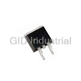
INTERNATIONAL RECTIFIER IR53HD420

Description
IR53HD420
Part Number
IR53HD420
Price
Request Quote
Manufacturer
INTERNATIONAL RECTIFIER
Lead Time
Request Quote
Category
PRODUCTS - I
Datasheet


Extracted Text
Preliminary Data Sheet No. PD60140-K IR53H(D)420 SELF-OSCILLATING HALF BRIDGE Features Product Summary • • • • • Output power MOSFETs in half-bridge configuration • • • High side gate drive designed for bootstrap operation • • V (max) • • • • • Bootstrap diode integrated into package (HD type) IN 500V • • • • • Tighter initial deadtime control • • • • • Low temperature coefficient deadtime Duty Cycle 50% • • • 15.6V zener clamped Vcc for offline operation • • Deadtime (type.) 1.2µs • • • • • Half-bridge output is out of phase with R T • • • True micropower startup • • R 3.0Ω ds(on) • • • • • Shutdown feature (1/6th V ) on C lead CC T o • • • • • Increased undervoltage lockout hysteresis (1Volt) P (T = 25 C) 2.0W or 3.0W D A • • • • • Lower power level-shifting circuit • • • Lower di/dt gate drive for better noise immunity • • • • • • • Excellent latch immunity on all inputs and outputs Package • • • • • ESD protection on all leads • • • • • Constant V pulse width at startup O • • • Heatsink package version (P2 type) • • Description The IR53H(D)420 are complete high voltage, high speed, self- oscillating half-bridge circuits. Proprietary HVIC and latch im- ® mune CMOS technologies, along with the HEXFET power 7-Lead SIP MOSFET technology, enable ruggedized single package con- struction. The front-end features a programmable oscillator which functions similar to the CMOS 555 timer. The supply to the control circuit has a zener clamp to simplify offline operation. The output features two HEXFETs in a half-bridge configuration with an internally set deadtime designed for minimum cross-conduction in the half-bridge. Propa- gation delays for the high and low side power MOSFETs are matched to simplify use in 50% duty cycle applications. The device can operate up to the V (max) rating. IN Typical Connection HV DC Bus IR53H(D)420 VIN D1 External 1 6 Vcc V B Fast recovery diode D1 is not required for HD type 2 9 R V T IN R T 3 7 C VO T C T 4 TO, COM LOAD COM www.irf.com 1 IR53H(D)420 Absolute Maximum Ratings Absolute maximum ratings indicate sustained limits beyond which damage to the device may occur. All volt- age parameters are absolute voltages referenced to COM, unless stated otherwise. All currents are defined positive into any lead. The thermal resistance and power dissipation ratings are measured under board mounted and still air conditions. Symbol Definition Minimum Maximum Units V High voltage supply - 0.3 500 IN V High side floating supply V - 0.3 V + 25 B o o V V Half-bridge output -0.3 V + 0.3 O IN V R voltage - 0.3 V + 0.3 RT T cc V C voltage - 0.3 V + 0.3 CT T cc I Supply current (note 1) — 25 cc mA I R output current - 5 5 RT T dV/dt Peak diode recovery — 3.50 V/ns P Package power dissipation @ T ≤ +25°C — 2 D A W -P2 — 3 Rth Thermal resistance, junction to ambient — 60 JA -P2 — 40 o C/W Rth Thermal resistance, junction to case -P2 — 20 JC (heatsink) T Junction temperature -55 150 J T Storage temperature -55 150 °C S T Lead temperature (soldering, 10 seconds) — 300 L NOTE 1: This IC contains a zener clamp structure between V and COM which has a nominal breakdown voltage of 15.6V. CC Please note that this supply pin should not be driven by a DC, low impedance power source greater than the V CLAMP specified in the Electrical Characteristics Section 2 www.irf.com IR53H(D)420 Recommended Component Values Symbol Definition Minimum Maximum Units R Timing resistor value 10 — kΩ T C C pin capacitor value 330 — pF T T IR53H(D)420 RT vs Frequency IR2153 RT vs Frequency 1000000 100000 10000 330pf 470pF 1nF CT Values 1000 2.2nF 4.7nF 10nF 100 10 10 100 1000 10000 100000 1000000 RT (ohms) www.irf.com 3 Frequency (Hz) IR53H(D)420 Recommended Operating Conditions The input/output logic timing diagram is shown in figure 1. For proper operation, the device should be used within the recommended conditions. Symbol Definition Minimum Maximum Units V High side floating supply absolute voltage V + 10 V + V B o o clamp V High voltage supply — 500 V IN V Half-bridge output voltage -3.0 (note 3) 500 O I Continuous drain current (T = 25°C) — D A 0.7 -P2 — 0.85 (T = 85°C) A A — 0.5 -P2 — 0.6 (T = 25°C) C -P2 — 1.2 I Supply current 5mA CC (note 3) T Ambient temperature -40 125 °C A NOTE 2: Care should be taken to avoid switching conditions where the V node flies inductively below ground by more than 5V. S NOTE 3: Enough current should be supplied to the V lead of the IC to keep the internal 15.6V zener diode clamping the CC voltage at this lead. Electrical Characteristics V (V , V ) = 12V, C = 1 nF and T = 25°C unless otherwise specified. The V , V and I parameters are BIAS CC BS T A IN TH IN referenced to COM. MOSFET Characteristics Symbol Definition Min. Typ. Max. Units Test Conditions t Reverse recovery time (MOSFET body diode) — 240 rr — di/dt = µC Q Reverse recovery charge (MOSFET body diode) rr — 0.5 — 100 I =700mA F R Static drain-to-source on resistance — 3.0 — Ω ds(on) A/µs V Diode forward voltage — 0.8 — V SD Dynamic Characteristics Symbol Definition Min. Typ. Max. Units Test Conditions D RT duty cycle 50 % fosc = 20 kHz — — tsd Shutdown propagation delay — 660 — nsec 4 www.irf.com IR53H(D)420 Electrical Characteristics V (V , V ) = 12V, C = 1 nF and T = 25°C unless otherwise specified. The V , V and I parameters are BIAS CC BS T A IN TH IN referenced to COM. Low Voltage Supply Characteristics Symbol Definition Min. Typ. Max. Units Test Conditions V Rising V undervoltage lockout threshold 8.1 9.0 9.9 CCUV+ CC V Falling V undervoltage lockout threshold 7.2 8.0 8.8 V CCUV- CC V V undervoltage lockout Hysteresis 0.5 1.0 1.5 CCUVH CC I Micropower startup V supply current — 75 150 V ≤ V QCCUV CC CC CCUV- µA I Quiescent V supply current — 500 950 QCC CC VCLAMP VCC zener clamp voltage 14.4 15.6 16.8 V ICC = 5mA Floating Supply Characteristics Symbol Definition Min. Typ. Max. Units Test Conditions I Micropower startup V supply current — 0 10 V ≤ V QBSUV BS CC CCUV- µA I Quiescent VBS supply current — 30 50 QBS V Minimum required V voltage for proper — 4.0 5.0 V V =V + 0.1V BSMIN BS CC CCUV+ functionality from R to HO T I Offset supply leakage current — — 50 µAV = V = 600V OS B S VF Bootstrap diode forward voltage (IR2153D) 0.5 — 1.0 V IF = 250mA Oscillator I/O Characteristics Symbol Definition Min. Typ. Max. Units Test Conditions f Oscillator frequency 19.4 20 20.6 R = 36.9kΩ osc T kHz 94 100 106 RT = 7.43kΩ d R pin duty cycle 48 50 52 % fo < 100kHz T I C pin current — 0.001 1.0 uA T CT I UV-mode C pin pulldown current 0.30 0.70 1.2 mA V = 7V T CTUV CC V Upper C ramp voltage threshold — 8.0 — CT+ T V V Lower C ramp voltage threshold — 4.0 — CT- T V C voltage shutdown threshold 1.8 2.1 2.4 CTSD T V High-level R output voltage, V - V — 10 50 I = 100µA T CC RT RT RT+ — 100 300 I = 1mA RT V Low-level R output voltage — 10 50 I = 100µA RT- T RT — 100 300 I = 1mA RT mV — 0 100 V ≤ V V UV-mode R output voltage RTUV T CC CCUV- V SD-Mode R output voltage, V - V — 10 50 I = 100µA, RTSD T CC RT RT V = 0V CT — 10 300 I = 1mA, RT V = 0V CT www.irf.com 5 IR53H(D)420 Functional Block Diagram V VIN B D1 6 9 1 Vcc IRFCXXX H O IR2153C 2 V 7 S R VO T L O 3 IRFCXXX C T 4 COM Fast recovery diode D1 is incorporated in IR53HDXXX only 6 www.irf.com IR53H(D)420 Lead Assignments 1 V 6 V cc B 2R 7 VO T 3C 9 V T IN 4 COM 9 7 6 4 3 2 9 Lead SIP without Leads 5 and 8 1 Lead Definitions Symbol Lead Description V Logic and internal gate drive supply voltage. CC R Oscillator timing resistor output T C Oscillator timing capacitor input T V High side gate drive floating supply. B V High voltage supply IN VO Half Bridge output COM Logic and low side of half bridge return Vccuv+ V CLAMP Vcc R T C T V+ VO 0 Figure 1. Input/Output Timing Diagram www.irf.com 7 IR53H(D)420 Case Outline - 7 pin 4X 5.08 (.100) 2X 16.89 (.665) 16.63 (.655) 3.18 (.125) 2.92 (.115) NOTES: 1. Dimensioning and tolerancing per ANSI Y14.5M-1982 2. Controlling dimension: Inch 3. Dimensions are shown in millimeters (inches) WORLD HEADQUARTERS: 233 Kansas St., El Segundo, California 90245 Tel: (310) 252-7105 http://www.irf.com Data and specifications subject to change without notice. 8/19/2003 8 www.irf.com
Frequently asked questions
What makes Elite.Parts unique?

What kind of warranty will the IR53HD420 have?
Which carriers does Elite.Parts work with?
Will Elite.Parts sell to me even though I live outside the USA?
I have a preferred payment method. Will Elite.Parts accept it?









What they say about us
FANTASTIC RESOURCE
One of our top priorities is maintaining our business with precision, and we are constantly looking for affiliates that can help us achieve our goal. With the aid of GID Industrial, our obsolete product management has never been more efficient. They have been a great resource to our company, and have quickly become a go-to supplier on our list!
Bucher Emhart Glass
EXCELLENT SERVICE
With our strict fundamentals and high expectations, we were surprised when we came across GID Industrial and their competitive pricing. When we approached them with our issue, they were incredibly confident in being able to provide us with a seamless solution at the best price for us. GID Industrial quickly understood our needs and provided us with excellent service, as well as fully tested product to ensure what we received would be the right fit for our company.
Fuji
HARD TO FIND A BETTER PROVIDER
Our company provides services to aid in the manufacture of technological products, such as semiconductors and flat panel displays, and often searching for distributors of obsolete product we require can waste time and money. Finding GID Industrial proved to be a great asset to our company, with cost effective solutions and superior knowledge on all of their materials, it’d be hard to find a better provider of obsolete or hard to find products.
Applied Materials
CONSISTENTLY DELIVERS QUALITY SOLUTIONS
Over the years, the equipment used in our company becomes discontinued, but they’re still of great use to us and our customers. Once these products are no longer available through the manufacturer, finding a reliable, quick supplier is a necessity, and luckily for us, GID Industrial has provided the most trustworthy, quality solutions to our obsolete component needs.
Nidec Vamco
TERRIFIC RESOURCE
This company has been a terrific help to us (I work for Trican Well Service) in sourcing the Micron Ram Memory we needed for our Siemens computers. Great service! And great pricing! I know when the product is shipping and when it will arrive, all the way through the ordering process.
Trican Well Service
GO TO SOURCE
When I can't find an obsolete part, I first call GID and they'll come up with my parts every time. Great customer service and follow up as well. Scott emails me from time to time to touch base and see if we're having trouble finding something.....which is often with our 25 yr old equipment.
ConAgra Foods