

 Manufacturers
INTEL S5000VCL
Description
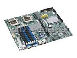
Intel S5000VCL CPU Board with DUAL 51XX Series(Woodcrest) Only SATA 5000VS FBDIMM Dual GBE
Part Number
S5000VCL
Price
Request Quote
Manufacturer
INTEL
Lead Time
Request Quote
Category
PRODUCTS - S
Specifications
Audio Output Type
None
BIOS Features
ACPI support, APM support, DMI support, IPMI support, SMBIOS support
Cables Included
2 x Serial ATA cable
Chipset Type
Intel 5000V
CPU Socket Type
LGA771 Socket
CPU Type
Dual-Core Xeon
Data Bus Speed
1333 MHz
Depth
30.5 cm
Form Factor
SSI CEB
Graphics Controller
ATI ES1000
Hardware Features
Chassis intrusion detection
Hardware Monitoring
CPU core temperature, CPU fan tachometer, chassis fan tachometer, chassis temperature, system voltage
Installed Qty (Max Supported)
2
Interfaces
1 x display / video - VGA - 15 pin HD D-Sub (HD-15), 1 x keyboard - generic - 6 pin mini-DIN (PS/2 style), 1 x mouse - generic - 6 pin mini-DIN (PS/2 style), 1 x serial - RS-232 - 9 pin D-Sub (DB-9), 2 x Hi-Speed USB - 4 pin USB Type A, 2 x network - Ethernet 10Base-T/100Base-TX/1000Base-T - RJ-45
Manufacturer
Intel
Model
S5000VCL
MPN
S5000VCL
Processor
Intel Xeon
Product Type
Motherboard
Software Included
Drivers & utilities
Storage Controllers
ATA-100, Serial ATA-300 (RAID)
Storage Interfaces
SATA-300 - connector(s): 6 x 7pin Serial ATA - 6 device(s) - RAID 0 / RAID 1 / RAID 10 ¦ ATA-100 - connector(s): 1 x 40pin IDC - 1 device(s)
Supported RAM Integrity Check
ECC
Supported RAM Technology
DDR2 SDRAM
UPC
0007358581830, 0027242712621, 0675900813403, 0735858183000
Width
26.7 cm
Features
- ATI ES1000
- Dual-Core Xeon
- Intel 5000V
- LGA771 Socket
Datasheet

Extracted Text
®
Intel Server Board S5000VCL
Technical Product Specification
Intel order number: D64569-007
Revision 2.3
May 2007
Enterprise Platforms and Services Division - Marketing
®
Revision History Intel Server Board S5000VCL TPS
Revision History
Date Revision Modifications
Number
September 2006 1.0 Initial release.
November 2006 2.0 Added technical updates and SAS board information.
January 2007 2.1 Removed processor that is not supported by board; added Post-Code Diagnostic
LED information.
September 2007 2.2 Updated product codes and processor information.
May 2010 2.3 Deleted CCC and CNCA.
Disclaimers
®
Information in this document is provided in connection with Intel products. No license, express or implied, by
estoppel or otherwise, to any intellectual property rights is granted by this document. Except as provided in Intel's
Terms and Conditions of Sale for such products, Intel assumes no liability whatsoever, and Intel disclaims any
express or implied warranty, relating to sale and/or use of Intel products including liability or warranties relating to
fitness for a particular purpose, merchantability, or infringement of any patent, copyright or other intellectual property
right. Intel products are not intended for use in medical, life saving, or life sustaining applications. Intel may make
changes to specifications and product descriptions at any time, without notice.
Designers must not rely on the absence or characteristics of any features or instructions marked "reserved" or
"undefined." Intel reserves these for future definition and shall have no responsibility whatsoever for conflicts or
incompatibilities arising from future changes to them.
®
The Intel Server Board S5000VCL may contain design defects or errors known as errata which may cause the
product to deviate from published specifications. Current characterized errata are available on request.
Intel Corporation server baseboards support peripheral components and contain a number of high-density VLSI and
power delivery components that need adequate airflow to cool. Intel’s own chassis are designed and tested to meet
the intended thermal requirements of these components when the fully integrated system is used together. It is the
responsibility of the system integrator that chooses not to use Intel developed server building blocks to consult vendor
datasheets and operating parameters to determine the amount of air flow required for their specific application and
environmental conditions. Intel Corporation can not be held responsible if components fail or the server board does
not operate correctly when used outside any of their published operating or non-operating limits.
Intel, Pentium, Itanium, and Xeon are trademarks or registered trademarks of Intel Corporation.
*Other brands and names may be claimed as the property of others.
Copyright © Intel Corporation 2010.
ii Revision 2.3
Intel order number: D64569-007
®
Intel Server Board S5000VCL TPS Table of Contents
Table of Contents
1 Introduction ..........................................................................................................................1
1.1 Server Board Use Disclaimer ..................................................................................1
2. Product Overview.................................................................................................................2
2.1 Feature Set ..............................................................................................................2
2.2 Server Board Layout................................................................................................3
®
2.2.1 Intel Light-Guided Diagnostics LED Locations.......................................................4
2.2.2 External I/O Connector Locations............................................................................5
3. Functional Architecture .......................................................................................................6
®
3.1 Intel 5000V Memory Controller Hub (MCH) ...........................................................8
3.1.1 System Bus Interface...............................................................................................8
3.1.2 Processor Support ...................................................................................................8
3.1.3 Memory Sub-system..............................................................................................10
®
3.2 Intel 6321ESB I/O Controller Hub ........................................................................12
3.2.1 PCI Sub-system.....................................................................................................13
3.2.2 Serial ATA Support ................................................................................................13
3.2.3 Parallel ATA (PATA) Support ................................................................................14
3.2.4 USB 2.0 Support....................................................................................................14
3.3 Video Support ........................................................................................................14
3.4 Network Interface Controller (NIC) ........................................................................15
®
3.4.1 Intel I/O Acceleration Technolgy ..........................................................................16
3.5 Super I/O ...............................................................................................................16
4. Platform Management........................................................................................................19
5. Connector/Header Locations and Pin-outs .....................................................................20
5.1 Board Connectors..................................................................................................20
5.2 Power Connectors .................................................................................................21
5.3 Riser Card Slots.....................................................................................................22
5.4 SSI Control Panel Connector.................................................................................22
5.5 I/O Connector Pinout Definition .............................................................................23
5.5.1 VGA Connector......................................................................................................23
5.5.2 NIC Connectors .....................................................................................................23
5.5.3 IDE Connector .......................................................................................................24
5.5.4 SATA Connectors ..................................................................................................25
5.5.5 Serial Port Connectors...........................................................................................26
5.5.6 Keyboard and Mouse Connector ...........................................................................26
5.5.7 USB Connector......................................................................................................27
5.6 Fan Headers ..........................................................................................................28
6. Jumper Block Settings ......................................................................................................29
6.1 Recovery Jumper Blocks .......................................................................................29
6.1.1 CMOS Clear and Password Reset Usage Procedure ...........................................30
Revision 2.3 iii
Intel order number: D64569-007
®
Table of Contents Intel Server Board S5000VCL TPS
6.1.2 BMC Force Update Procedure ..............................................................................30
6.2 BIOS Select Jumper ..............................................................................................31
6.3 PCI Express* Select Jumper .................................................................................31
®
7. Intel Light Guided Diagnostics........................................................................................32
7.1 5-Volt Standby System Status/Fault LED ..............................................................32
7.2 DIMM LEDs ...........................................................................................................34
7.3 Post Code Diagnostic LEDs ..................................................................................35
8. Power and Environmental Specifications........................................................................36
®
8.1 Intel Server Board S5000VCL Design Specifications ..........................................36
8.2 Baseboard Power Requirements...........................................................................37
8.2.1 Processor Power Support......................................................................................37
8.2.2 Power Supply Output Requirements .....................................................................37
8.2.3 Turn On No Load Operation ..................................................................................38
8.2.4 Grounding ..............................................................................................................39
8.2.5 Standby Outputs ....................................................................................................39
8.2.6 Remote Sense .......................................................................................................39
8.2.7 Voltage Regulation ................................................................................................39
8.2.8 Dynamic Loading ...................................................................................................40
8.2.9 Capacitive Loading ................................................................................................40
8.2.10 Closed-Loop Stability.............................................................................................40
8.2.11 Common Mode Noise ............................................................................................40
8.2.12 Ripple/Noise ..........................................................................................................41
8.2.13 Soft Starting ...........................................................................................................41
8.2.14 Timing Requirements.............................................................................................41
8.2.15 Residual Voltage Immunity in Standby Mode ........................................................43
9. Regulatory and Certification Information.........................................................................44
9.1 Product Regulatory Compliance ............................................................................44
9.1.1 Product Safety Compliance ...................................................................................44
9.1.2 Product EMC Compliance – Class A Compliance .................................................45
9.1.3 Certifications/Registrations/Declarations ...............................................................45
9.2 Product Regulatory Compliance Markings ............................................................46
9.3 Electromagnetic Compatibility Notices ..................................................................47
9.3.1 FCC Verification Statement (USA) ........................................................................47
9.3.2 ICES-003 (Canada) ...............................................................................................48
9.3.3 Europe (CE Declaration of Conformity) .................................................................48
9.3.4 VCCI (Japan) .........................................................................................................48
9.3.5 BSMI (Taiwan) .......................................................................................................48
9.3.6 RRL (Korea)...........................................................................................................49
9.4 Restriction of Hazardous Substances (RoHS) Compliance...................................49
Appendix A: Integration and Usage Tips................................................................................50
Appendix B: Sensor Tables .....................................................................................................51
iv Revision 2.3
Intel order number: D64569-007
®
Intel Server Board S5000VCL TPS Table of Contents
Appendix C: POST Error Messages and Handling ................................................................53
Appendix D: POST Code Diagnostic LED Decoder ...............................................................56
®
Appendix E: Supported Intel Server Chassis.......................................................................60
Glossary.....................................................................................................................................62
Reference Documents ..............................................................................................................65
Revision 2.3 v
Intel order number: D64569-007
®
List of Figures Intel Server Board S5000VCL TPS
List of Figures
Figure 1. Components and Connector Location Diagram.............................................................3
®
Figure 2. Intel Light-Guided Diagnostics LED Locations.............................................................4
Figure 3. ATX I/O Layout ..............................................................................................................5
Figure 4. Functional Block Diagram..............................................................................................7
Figure 5. CEK Processor Mounting ............................................................................................10
Figure 6. Memory Layout ............................................................................................................10
Figure 7. SMBUS Block Diagram................................................................................................19
Figure 8. Recovery Jumper Blocks (J3A1, J1C2, J1C4).............................................................29
Figure 9. System Status/Fault LED Location ..............................................................................32
Figure 10. DIMM LED Locations.................................................................................................34
Figure 11. POST Code Diagnostic LED Location .......................................................................35
Figure 12. Output Voltage Timing ...............................................................................................42
Figure 13. Turn On/Off Timing (Power Supply Signals)..............................................................43
Figure 14. Diagnostic LED Placement Diagram .........................................................................56
®
Figure 15. Intel Server System SR1530CL/SR1530CLR..........................................................60
®
Figure 16. Intel Server System SR1530HCL/SR1530HCLR.....................................................61
vi Revision 2.3
Intel order number: D64569-007
®
Intel Server Board S5000VCL TPS List of Tables
List of Tables
Table 1. Processor Support Matrix ...............................................................................................9
2
Table 2. I C Addresses for Memory Module SMB ......................................................................11
Table 3. Maximum Six-DIMM System Memory Configuration – x4 Single Rank ........................11
Table 4. Maximum Six-DIMM System Memory Configuration – x8 Dual Rank...........................11
Table 5. PCI Bus Segment Characteristics.................................................................................13
Table 6. Video Modes .................................................................................................................15
Table 7. NIC2 Status LED...........................................................................................................16
Table 8. Serial A Port Header Pin-out (External DB9) ................................................................17
Table 9. Internal Serial B Port Header Pin-out............................................................................17
Table 10. Board Connector Matrix ..............................................................................................20
Table 11. Power Connector Pin-out (J3K3) ................................................................................21
Table 12. 12V Power Connector Pin-out (J9E1).........................................................................21
Table 13. Power Supply Signal Connector Pin-out (J9C1) .........................................................22
Table 14. Front Panel SSI Standard 24-pin Connector Pin-out (J2K2) ......................................22
Table 15. VGA Connector Pin-out (J7A1)...................................................................................23
Table 16. RJ-45 10/100/1000 NIC Connector Pin-out (JA6A1, JA5A1)......................................23
Table 17. 44-pin IDE Connector Pin-out (J2K5) .........................................................................24
Table 18. SATA Connector Pin-out (J1J2, J1J1) ........................................................................25
Table 19. SATA/SAS Connector Pin-out (J1G2, J1G1, J1F1, J1E4)..........................................25
Table 20. 9-pin Serial Header Pin-out (J8A1, J1A1)...................................................................26
Table 21. Stacked PS/2 Keyboard and Mouse Port Pin-out (J9A2) ...........................................26
Table 22. External USB Connector Pin-out (J9A2).....................................................................27
Table 23. Internal USB Connector Pin-out (J3K1) ......................................................................27
Table 24. CPU Fan Connector Pin-out (J2K3, J2K4) .................................................................28
Table 25. PCI Fan Connector Pin-out (J1K1) .............................................................................28
Table 26. Recovery Jumpers (J3A1, J1C1, J1C2)......................................................................29
Table 27. BIOS Select Jumper (J3A2) .......................................................................................31
Table 28. PCI Express* x4/x8 Select Jumper (J1E1) .................................................................31
Table 29. 5V Standby System Status LED Indicators.................................................................33
Table 30. Server Board Design Specifications ...........................................................................36
® ® ® ®
Table 31. Dual-Core Intel Xeon processor 5100 series and Quad-Core Intel Xeon processor
5300 series TDP Guidelines.................................................................................................37
Table 32. 400W Load Ratings ....................................................................................................38
Table 33. No-load Operating Range ...........................................................................................38
Table 34. Voltage Regulation Limits ...........................................................................................39
Table 35. Transient Load Requirements.....................................................................................40
Table 36. Capacitive Loading Conditions ...................................................................................40
Table 37. Ripple and Noise.........................................................................................................41
Table 38. Output Voltage Timing ................................................................................................41
Revision 2.3 vii
Intel order number: D64569-007
®
List of Tables Intel Server Board S5000VCL TPS
Table 39. Turn On/Off Timing .....................................................................................................42
Table 40. POST Error Messages and Handling..........................................................................53
Table 41. POST Error Beep Codes ............................................................................................55
Table 42. BMC Beep Codes .......................................................................................................55
Table 43. Example POST Progress Code LED ..........................................................................56
Table 44. Diagnostic LED POST Code Decoder ........................................................................57
viii Revision 2.3
Intel order number: D64569-007
®
Intel Server Board S5000VCL TPS List of Tables
< This page intentionally left blank. >
Revision 2.3 ix
Intel order number: D64569-007
®
Intel Server Board S5000VCL TPS Introduction
1 Introduction
This Technical Product Specification (TPS) provides board-specific information about the
®
features, functionality, and high-level architecture of the Intel Server Board S5000VCL. See the
®
Intel 5000 Series Chipsets Server Board Family Datasheet more information about board sub-
systems, including chipset, BIOS, system management, and system management software.
There are four product codes of the Intel Server Board S5000VCL:
SS5000VCL
S5000VCLSASBB
BBS5000VCLR
BBS5000VCLSASR
®
All references to the Intel Server Board S5000VCL refer to all product codes listed above,
unless noted otherwise.
1.1 Server Board Use Disclaimer
Intel Corporation server boards support add-in peripherals and contain high-density VLSI and
power delivery components that need adequate airflow to cool. Intel ensures through its own
chassis development and testing that when Intel server building blocks are used together, the
fully integrated system will meet the intended thermal requirements of these components. It is
the responsibility of the system integrator who chooses not to use Intel developed server
building blocks to consult vendor datasheets and operating parameters to determine the amount
of air flow required for their specific application and environmental conditions. Intel Corporation
cannot be held responsible if components fail or the server board does not operate correctly
when used outside any of their published operating or non-operating limits.
Revision 2.3 1
Intel order number: D64569-007
®
Product Overview Intel Server Board S5000VCL TPS
2. Product Overview
®
The Intel Server Board S5000VCL is a monolithic printed circuit boards that support the high-
density 1U server market.
2.1 Feature Set
Feature Description
® ®
Processors 771-pin LGA sockets supporting one or two Dual-Core Intel Xeon processors 5100
® ®
series and low-voltage Quad-Core Xeon processors 5300 series, with system bus
speeds of 1066 MHz or 1333 MHz.
For a complete list of supported processors, see the following link:
http://support.intel.com/support/motherboards/server/S5000VCL
Memory Six keyed DIMM slots support fully buffered DIMM technology (FBDIMM) memory. 240-
pin DDR2-677 FBDIMMs must be used.
®
Chipset Intel 5000V Chipset family, which includes the following components:
®
Intel 5000V Memory Controller Hub
®
Intel 6321ESB I/O Controller Hub
On-board External connections:
Connectors/Headers
Stacked PS/2* ports for keyboard and mouse
Two RJ45 NIC connectors for 10/100/1000 Mb connections
Two USB 2.0 ports
Video connector
Com 1 or Serial A (DB9)
Internal connectors/headers:
One USB port header, capable of providing two USB 2.0 ports
One DH10 Serial B header
®
Six SATA ports or four SAS ports via the Intel 6321ESB I/O Controller Hub.
These ports support 3Gb/s and integrated SW RAID 0 or 1
One 40-pin (power + I/O) ATA/100 connector for optical drive support
SSI-compliant 24-pin control panel header
SSI-compliant 24-pin main power connector support the ATX-12 V standard on
the first 20 pins
8-pin +12 V processor power connector
Add-in PCI, PCI-X*, PCI One PCI super-slot that will support one 1U riser card with one PCI-X* and one PCI
Express* Cards Express* connectors
On-board Video ATI* ES1000 video controller with 16 MB DDR SDRAM
On-board Hard Drive Six 3 Gb/s SATA ports, or four SAS ports
®
Controller
Intel Embedded Server RAID Technology II with RAID levels 0, 1, 10
®
LAN
Two 10/100/1000 NICs supporting Intel I/O Acceleration Technology
System Fans Two CPU 4-pin fan headers supporting two system blowers and one 3-pin fan header
supporting a system fan
®
System Management
Support for Intel System Management Software
2 Revision 2.3
Intel order number: D64569-007
®
Intel Server Board S5000VCL TPS Product Overview
2.2 Server Board Layout
A B C D E
Z
Y
F
G
X
H
W
V
U
I
T
S
R
Q
P
O
N M L K J
AF002052
Figure 1. Components and Connector Location Diagram
Description Description
A Post code Diagnostic LEDs O System Fan Header
B System Fault/Status LED P SATA 0
C Speaker Q SATA 1
D Super Slot (Slot 6) R SSI 24-pin Control Panel Header
E External IO Connectors S CPU 1 Fan Header
F Main Power Connector T SATA 2/SAS 0
G Power Supply Auxiliary Connector U SATA 3/SAS 1
H CPU Power Connector V SATA 4/SAS 2
I FBDIMM Slots W SATA 5/SAS 3
J CPU Socket 1 X Battery
K CPU Socket 2 Y SATA SGPIO
L CPU 2 Fan Header Z Serial B Port Header
M Dual Port USB 2.0 Header Not shown SAS GPIO (SAS version of the server board only)
N Primary IDE Connector
Revision 2.3 3
Intel order number: D64569-007
®
Product Overview Intel Server Board S5000VCL TPS
®
2.2.1 Intel Light-Guided Diagnostics LED Locations
A B
D
H G F E C
AF002053
Description Description
A Post-Code Diagonstic LEDs E CPU 2 Fan Fault LED
B System Fault/Status LED F CPU 1 Fan Fault LED
C CPU 1 Fault LED G System Fan Fault LED
D DIMM Fault LEDs H 5 VSB LED
E CPU 2 Fault LED
®
Figure 2. Intel Light-Guided Diagnostics LED Locations
4 Revision 2.3
Intel order number: D64569-007
®
Intel Server Board S5000VCL TPS Product Overview
2.2.2 External I/O Connector Locations
A
C
D E F G
NIC1 NIC2
Serial A
B
10/100/ 10/100/
1000 Mb 1000 Mb
USB
0-1
Network
AF001640
Figure 3. ATX I/O Layout
Revision 2.3 5
Intel order number: D64569-007
®
Functional Architecture Intel Server Board S5000VCL TPS
3. Functional Architecture
® ®
The architecture and design of the Intel Server Board S5000VCL is based on the Intel 5000V
® ®
Chipset. The chipset is for systems based on the Dual-Core Intel Xeon processor 5100 series
® ®
and low-voltage Quad-Core Intel Xeon processor 5300 series with system bus speeds of
1067 MHz and 1333 MHz.
®
The chipset has two main components: the Intel 5000V Memory Controller Hub (MCH) for the
®
host bridge and the Intel 6321ESB I/O Controller Hub for the I/O subsystem.
This chapter provides a high-level description of the functionality associated with each chipset
component and the architectural blocks that make up this server board. For in depth information
®
on each of the chipset components and each of the functional architecture blocks, see the Intel
5000 Series Chipsets Server Board Family Datasheet.
6 Revision 2.3
Intel order number: D64569-007
®
Intel Server Board S5000VCL TPS Functional Architecture
1333 MT/s
Super Slot
Serial Port B (Internal)
Serial Port A (Back Panel)
PCI-X* 64-bit/133 MHz
PCI-Express x4 (ESB2, Port 1)
PCI-Express x4 (ESB2, Port 2)
PATA
ATI*
ES1000
Video
GBE PCI-X x4
LSI* 1064E
SATA0 SATA2 / SAS0
SATA1 SATA3 / SAS1
SATA4 / SAS2
SATA5 / SAS3
Figure 4. Functional Block Diagram
Revision 2.3 7
Intel order number: D64569-007
®
Functional Architecture Intel Server Board S5000VCL TPS
®
3.1 Intel 5000V Memory Controller Hub (MCH)
The memory controller hub (MCH) is a single 1432 pin FCBGA package that includes these
core platform functions:
System bus interface for the processor sub-system
Memory controller
PCI Express* ports including the enterprise south bridge interface (ESI)
FBD thermal management
SMBUS interface
3.1.1 System Bus Interface
The MCH is configured for symmetric multi-processing across two independent front side bus
interfaces that connect to the processors. Each front side bus on the MCH uses a 64-bit wide
1066- or 1333-MHz data bus. The 1333-MHz data bus can transfer data at up to 10.66 GB/s.
The MCH supports a 36-bit wide address bus, capable of addressing up to 64 GB of memory.
The MCH is the priority agent for both front side bus interfaces, and is optimized for one
processor on each bus.
3.1.2 Processor Support
® ®
The server board supports one or two Dual-Core Intel Xeon processors 5100 series or low
® ®
voltage Quad-Core Intel Xeon processor 5300 series, with system bus speeds of 1066 MHz,
®
and 1333 MHz, and core frequencies starting at 1.6 GHz. Previous generations of the Intel
®
Xeon processor are not supported.
For a complete list of supported processors, see the following link:
http://support.intel.com/support/motherboards/server/S5000VCL
® ® ®
Note: Only Dual-Core Intel Xeon processors 5100 series or low-voltage Quad-Core Intel
®
Xeon processor 5300 series, that support system bus speeds of 1066 MHz, and 1333 MHz are
supported.
8 Revision 2.3
Intel order number: D64569-007
®
Intel Server Board S5000VCL TPS Functional Architecture
Table 1. Processor Support Matrix
System Bus Speed Core Frequency Support
533 MHz All No
® ®
Intel Xeon
800 Mhz All No
processor
667 MHz All No
1066 MHz 1.60 GHz Yes
1066 MHz 1.86 GHz Yes
®
Dual-Core Intel
1333 MHz 2.00 GHz Yes
®
Xeon processor
1333 MHz 2.33 GHz Yes
5100 series
Yes
1333 MHz 2.66 GHz
1333 MHz 3.00 GHz Yes
1.60 GHz Yes
1066 MHz
Low-Voltage Quad-
® ®
1.86 GHz Yes
Core Intel Xeon 1066 MHz
processor 5300
1333 MHz 2.00 GHz
Yes
series
1333 MHz 2.33 GHz
Yes
3.1.2.1 Processor Population Rules
When two processors are installed, both must be of identical revision, core voltage, and
bus/core speed. When only one processor is installed, it must be in the socket labeled CPU1.
The other socket must be empty.
The board provides up to 90A max, 70A TDC per processor. Processors with higher current
requirements are not supported.
3.1.2.2 Common Enabling Kit (CEK) Design Support
The server board complies with Intel’s common enabling kit (CEK) processor mounting and heat
sink retention solution. The server board ships with a CEK spring snapped onto the underside of
the server board, beneath each processor socket. The heat sink attaches to the CEK, over the
top of the processor and the thermal interface material (TIM). See the figure below for the
stacking order of the chassis, CEK spring, server board, TIM, and heat sink.
The CEK spring is removable, allowing for the use of non-Intel heat sink retention solutions.
Revision 2.3 9
Intel order number: D64569-007
®
Functional Architecture Intel Server Board S5000VCL TPS
Heatsink assembly
Thermal Interface
Material (TIM)
TP02091
Server Board
CEK Spring
Chassis
AF001010
Figure 5. CEK Processor Mounting
3.1.3 Memory Sub-system
The MCH masters two fully buffered DIMM (FBDIMM) memory channels. FBDIMM memory
utilizes a narrow high-speed frame-oriented interface referred to as a channel. The two
channels are routed to six DIMM slots and support registered DDR2-667 FBDIMM memory
(stacked or unstacked). Peak FBDIMM memory data bandwidth in dual channel mode is
8.0GB/s (2x4.0 GB/s) with DDR2-667/PC2-5300 (3.0 ns at CL5).
Channel A
Channel B
AF001011
Figure 6. Memory Layout
10 Revision 2.3
Intel order number: D64569-007
DIMM A1
DIMM A2
DIMM A3
DIMM B1
DIMM B2
DIMM B3
®
Intel Server Board S5000VCL TPS Functional Architecture
2
To boot the system, the system BIOS uses a dedicated I C bus to retrieve DIMM information
needed to program the MCH memory registers.
2
Table 2. I C Addresses for Memory Module SMB
Device Address
DIMM A1 0xA0
DIMM A2 0xA2
DIMM A3 A4
DIMM B1 A0
DIMM B2 A2
DIMM B3 A4
3.1.3.1 Supported Memory
Up to six DDR2-667 fully-buffered DIMMs (FBD memory) can be installed.
Table 3. Maximum Six-DIMM System Memory Configuration – x4 Single Rank
DRAM Technology x4 Single Rank Maximum Capacity Non-Mirrored Mode
256 Mb 1.5 GB
512 Mb 3 GB
1024 Mb 6 GB
2048 Mb 12 GB
Table 4. Maximum Six-DIMM System Memory Configuration – x8 Dual Rank
DRAM Technology x8 Dual Rank Maximum Capacity Non-Mirrored Mode
256 Mb 1.5 GB
512 Mb 3 GB
1024 Mb 6 GB
2048 Mb 12 GB
®
Note: DDR2 DIMMs that are not fully buffered are NOT supported. See the Intel Server Board
S5000VCL Tested Memory List for a list of supported memory.
Revision 2.3 11
Intel order number: D64569-007
®
Functional Architecture Intel Server Board S5000VCL TPS
3.1.3.2 DIMM Population Rules and Supported DIMM Configurations
DIMM population rules depend on the operating mode of the memory controller. The operating
mode is determined by the number of DIMMs installed. DIMMs must be populated in pairs in
DIMM slot order: A1 & B1, A2 & B2. DIMMs within a pair must be identical with respect to size,
speed, and organization, but DIMM capacities can be different across different DIMM pairs.
Note: The server board supports single DIMM mode operation. Intel will only validate and
support this configuration with a single 512 MB x8 FBDIMM installed in DIMM slot A1.
®
3.2 Intel 6321ESB I/O Controller Hub
®
The Intel 6321ESB I/O Controller Hub is a multi-function device that provides four distinct
functions: an IO Controller, a PCI-X* Bridge, a GB Ethernet Controller, and a baseboard
management controller (BMC). Each function within the controller hub has its own set of
configuration registers. Once configured, each appears to the system as a distinct hardware
controller.
The controller hub provides the gateway to all PC-compatible I/O devices and features. The
®
server board uses these Intel 6321ESB I/O Controller Hub features:
1. PCI-X* bus interface
2. Six channel SATA interface w/SATA busy and fault LED control
3. Dual GbE MAC
4. Baseboard management controller (BMC)
5. Single ATA interface, with Ultra DMA 100 capability
6. Universal Serial Bus 2.0 (USB) interface
7. Removable media drives
8. LPC bus interface
9. PC-compatible timer/counter and DMA controllers
10. APIC and 8259 interrupt controller
11. Power management
12. System RTC
13. VT technology
14. General purpose I/O
®
For additional information, see the Intel 5000 Series Chipsets Server Board Family Datasheet.
12 Revision 2.3
Intel order number: D64569-007
®
Intel Server Board S5000VCL TPS Functional Architecture
3.2.1 PCI Sub-system
The primary I/O buses support one Super Slot connector, which supports one PCI riser
assembly that supports two PCI slots: one low-profile PCI Express* x8, and either a mid-height
PCI-X* 133, or one low-profile PCI Express*x4 and one mid-height PCI Express x4. The PCI
bus complies with the PCI Local Bus Specification, Revision 2.3. The PCI-X bus complies with
PCI-X Local BUS Specification, Revision 2.0, the PCI Express ports comply with the PCI
Express Base Specification, Revision 1.0a. PCI 32 supports the VGA ATI* ES1000 video
controller.
Table 5. PCI Bus Segment Characteristics
PCI Bus Segment Voltage Width Speed Type On-board Device Support
PXA 3.3V/5.0V 64 bit 133 MHz PCI-X* Full-height riser slot
6321ESB
PE1, PE2 3.3V x8 20 Gb/S PCI Low-profile riser slot
Express*
BNB PCI Express*
Ports 4, 5
3.2.1.1 PXA: 64-bit, 133MHz PCI Subsystem
One 64-bit PCI-X* bus segment is directed through the 6321ESB ICH6. This PCI-X segment,
PXA, supports up to three PCI add-in cards on the full-height riser card.
3.2.1.2 PE2: One x4 PCI Express* Bus Segment
One x4 PCI Express* bus segment is directed through the 6321ESB. This PCI Express
segment, PE2, supports one x8 PCI Express segment to the proprietary I/O module mezzanine
connector.
3.2.1.3 PCI Riser Slot
The primary I/O buses for this server board supports one Super Slot connector which supports
one PCI riser assembly supporting two PCI slots:
One low-profile PCI Express* x8 and one mid-height PCI-X* 133.
Or one low-profile PCI Express*x4 and one mid-height PCI Express* x4.
3.2.2 Serial ATA Support
®
The Intel 6321ESB I/O Controller Hub has an integrated Serial ATA (SATA) controller that
supports independent DMA operation on six ports and supports data transfer rates of up to
3.0 Gb/s. The six SATA ports on the server board are numbered SATA-0 thru SATA-5. The
SATA ports can be enabled/disabled and/or configured through the BIOS Setup Utility.
®
3.2.2.1 Intel Embedded Server RAID Technology Support
®
The embedded Intel Embedded Server RAID Technology solution offers data stripping (RAID
Level 0) and data mirroring (RAID Level 1). For higher performance, data stripping alleviates
disk bottlenecks by taking advantage of the dual independent DMA engines that each SATA
port offers.
Revision 2.3 13
Intel order number: D64569-007
®
Functional Architecture Intel Server Board S5000VCL TPS
Data mirroring is for data security. If a disk fails, a mirrored copied of the failed disk is brought
on-line. There is no loss of either PCI resources (request/grant pair) or add-in card slots.
®
Intel Embedded Server RAID Technology functionality requires these items:
®
Intel 6321ESB I/O Controller Hub
®
Intel Embedded Server RAID Technology Option ROM
®
Intel Application Accelerator RAID edition drivers, most recent revision
At least two SATA hard disk drives
®
Intel Embedded Server RAID Technology is not available in these configurations:
The SATA controller in compatible mode
®
Intel Embedded Server RAID Technology has been disabled
3.2.3 Parallel ATA (PATA) Support
The integrated IDE controller of the 6321ESB ICH6 provides one IDE channel. It redefines
signals on the IDE cable to allow both host and target throttling of data and transfer rates of up
to 100 MB/s. The IDE channel provides optical drive support. The BIOS initializes and supports
ATAPI devices such as LS-120/240, CD-ROM, CD-RW and DVD-ROM. The IDE channel is
accessed through a high-density 40-pin connector ((J2K5) that provides I/O signals. The ATA
channel can be configured and enabled or disabled through the BIOS Setup Utility.
3.2.4 USB 2.0 Support
The USB controller functionality integrated into the 6321ESB provides the interface for up to
four USB 2.0 ports. Two external connectors are located on the back edge of the server board
and one internal 2x5 header supports two optional USB 2.0 ports.
3.3 Video Support
An ATI* ES1000 PCI graphics accelerator with 16 MB of video DDR SDRAM and support
circuitry for an embedded SVGA video sub-system is provided. The ATI ES1000 chip contains
an SVGA video controller, clock generator, 2D engine, and RAMDAC in a 359-pin BGA. One
4M x 16 x 4 bank DDR SDRAM chip provides 16 MB of video memory.
The SVGA sub-system supports modes up to 1024 x 768 resolution in 8/16/32 bpp modes
under 2D. It also supports both CRT and LCD monitors up to a 100 Hz vertical refresh rate.
Video is accessed using a standard 15-pin VGA connector found on the back edge of the server
board. Video signals are also made available through the 120-pin bridge-board connector that
provides signals for an optional video connector on the control panel. Video is routed to both the
rear video connector and a control panel video connector. Video is present at both connectors
simultaneously and cannot be disabled at either connector individually. Video monitors can be
hot-plugged.
14 Revision 2.3
Intel order number: D64569-007
®
Intel Server Board S5000VCL TPS Functional Architecture
3.3.1.1 Video Modes
The ATI* ES1000 chip supports all standard IBM* VGA modes. The table shows the 2D modes
supported for both CRT and LCD.
Table 6. Video Modes
2D Video Mode Support
2D Mode Refresh Rate (Hz)
8 bpp 16 bpp 32 bpp
640x480 60, 72, 75, 85, 90, 100, Supported Supported Supported
120, 160, 200
800x600 60, 70, 72, 75, 85, 90, Supported Supported Supported
100, 120, 160
1024x768 60, 70, 72, 75, 85, 90, Supported Supported Supported
100
1152x864 43, 47, 60, 70, 75, 80, Supported Supported Supported
85
1280x1024 60, 70, 74, 75 Supported Supported Supported
1600x1200 52 Supported Supported Supported
3.3.1.2 Video Memory Interface
The memory controller sub-system of the ES1000 arbitrates requests from the direct memory
interface, the VGA graphics controller, the drawing co-processor, the display controller, the
video scalar, and the hardware cursor. Requests are serviced in a manner that ensures display
integrity and maximum CPU/co-processor drawing performance.
The server board supports a 16 MB (4 Meg x 16-bit x four banks) DDR SDRAM device for video
memory.
3.4 Network Interface Controller (NIC)
Network interface support is provided from the built in Dual GbE MAC features of the 6321ESB
®
in conjunction with the Intel 82563EB compact Physical Layer Transceiver (PHY). Together,
they provide support for dual LAN ports designed for 10/100/1000 Mbps operation.
The 82563EB device is based upon proven PHY technology integrated into Intel’s gigabit
Ethernet controllers. The physical layer circuitry provides a standard IEEE 802.3 Ethernet
interface for 1000BASE-T, 100BASE-TX, and 10BASE-T applications (802.3, 802.3u, and
802.3ab). The 82563EB device can transmit and receive data at rates of 1000 Mbps, 100 Mbps,
or 10 Mbps.
Revision 2.3 15
Intel order number: D64569-007
®
Functional Architecture Intel Server Board S5000VCL TPS
Each network interface controller (NIC) drives two LEDs located on each network interface
connector. The link/activity LED at the right of the connector indicates network connection when
on, and Transmit/Receive activity when blinking. The speed LED at the left indicates 1000-Mbps
operation when amber, 100-Mbps operation when green, and 10-Mbps when off.
Table 7. NIC2 Status LED
LED Color LED State NIC State
Off 10 Mbps
Green/Amber (Left)
Green 100 Mbps
Amber 1000 Mbps
On Active Connection
Green (Right)
Blinking Transmit/Receive activity
®
3.4.1 Intel I/O Acceleration Technolgy
® ® ®
Intel I/O Acceleration Technology moves network data efficiently through Intel Xeon
processor-based servers for improved application responsiveness across diverse operating
systems and virtualized environments.
® ®
Intel I/OAT improves network application responsiveness by unleashing the power of Intel
®
Xeon processors through efficient network data movement and reduced system overhead. Intel
multi-port network adapters with Intel I/OAT provide high-performance I/O for server
consolidation and virtualization via stateless network acceleration that seamlessly scales across
multiple ports and virtual machines. Intel I/OAT provides safe and flexible network acceleration
through tight integration into popular operating systems and virtual machine monitors, avoiding
the support risks of third-party network stacks and preserving existing network requirements
such as teaming and failover.
3.5 Super I/O
Legacy I/O support is provided by a National Semiconductor* PC87427 Super I/O device. This
chip contains the necessary circuitry to support these functions:
GPIOs
Serial ports
Keyboard and mouse support
Wake up control
System health support
16 Revision 2.3
Intel order number: D64569-007
®
Intel Server Board S5000VCL TPS Functional Architecture
3.5.1.1 Serial Ports
The server board provides an external DB9 serial port and an internal serial header.
Table 8. Serial A Port Header Pin-out (External DB9)
RJ45 Signal Abbreviation DB9
1 Request to Send RTS 7
2 Data Terminal Ready DTR 4
3 Transmitted Data TD 3
4 Signal Ground SGND 5
5 Ring Indicator RI 9
6 Received Data RD 2
7 DCD or DSR DCD/DSR 1 or 6 (see note)
8 Clear To Send CTS 8
Table 9. Internal Serial B Port Header Pin-out
Pin Signal Name Serial Port A Header Pin-out
1 DCD
2 DSR
3 RX
4 RTS
5 TX
6 CTS
7 DTR
8 RI
9 GND
Note: The RJ45-to-DB9 adapter should match the configuration of the serial device used. One
of two pin-out configurations is used, depending on whether the serial device requires a DSR or
DCD signal. The final adapter configuration should also match the desired pin-out of the RJ45
connector, as it can also be configured to support either DSR or DCD.
3.5.1.2 Floppy Disk Controller
The server board does not support a floppy disk controller (FDC) interface, but the system BIOS
recognizes USB floppy devices.
Revision 2.3 17
Intel order number: D64569-007
®
Functional Architecture Intel Server Board S5000VCL TPS
3.5.1.3 Keyboard and Mouse Support
Dual stacked PS/2 ports on the back edge of the server board support a keyboard and mouse.
Either port can support a mouse or keyboard. Neither port supports hot plugging.
3.5.1.4 Wake-up Control
The super I/O contains functionality allows events to power-on and power-off the system.
3.5.1.5 System Health Support
The super I/O provides an interface via GPIOs for BIOS and system management firmware to
activate the diagnostic LEDs, the FRU fault indicator LEDs for processors, FBDIMMS, fans, and
the system status LED. See section 7 to locate the LEDs.
18 Revision 2.3
Intel order number: D64569-007
®
Intel Server Board S5000VCL TPS Platform Management
4. Platform Management
The platform management sub-system is based on the integrated baseboard management
®
controller (BMC) features of the Intel 6321ESB I/O Controller Hub. The onboard platform
management subsystem consists of communication buses, sensors, system BIOS, and system
management firmware.
See Appendix B for onboard sensor data. For additional platform management information see
®
the Intel 5000 Series Chipsets Server Board Family Datasheet.
LM4
Figure 7. SMBUS Block Diagram
Revision 2.3 19
Intel order number: D64569-007
®
Connector/Header Locations and Pin-outs Intel Server Board S5000VCL TPS
5. Connector/Header Locations and Pin-outs
5.1 Board Connectors
Table 10. Board Connector Matrix
Connector Quantity Server Board Reference Designators Connector Type Pin Count
Power supply 3 J9E1 CPU Power 8
J9B1 Main Power 24
J9C1 P/S Aux 5
CPU 2 J8H1, J5H1 CPU Sockets 771
Main Memory 8 J7A2, J7A3, J7A4, J7A5, J8A2, J8A3 DIMM Sockets 240
Super Slot 1 J4B2 Card Edge 98
IDE 1 J2K5 Shrouded Header 40
CPU Blowers #1 2 J2K3, J2K4 Header 4
and #2
System Fan 2 J1K1 Header 3
Battery 1 XBT3E1 Battery Holder 3
Keyboard/Mouse 1 J9A2 PS2, stacked 12
Rear USB 2 J9A2 External 4
Serial Port A 1 J8A1 External 9
Serial Port B 1 J1A1 Header 9
Video connector 1 J7A1 External, D-Sub 15
LAN connector 2 JA6A1, JA5A1 External LAN connector 14
10/100/1000 with built-in magnetic
SSI Control Panel 1 J2K2 Header 24
Internal USB 1 J3K1 Header 10
Serial ATA (SATA) 2 J1J1, J1J2 Header 7
SATA/SAS 4 J1G2, J1G1, J1F1, J1E4 Header 7
System Recovery 4 J1C2, J1C4 Jumper 3
Setting Jumpers
20 Revision 2.3
Intel order number: D64569-007
®
Intel Server Board S5000VCL TPS Connector/Header Locations and Pin-outs
5.2 Power Connectors
The main power supply connection is obtained using an SSI compliant 2x12 pin connector
(J9B1). Two additional power related connectors; one SSI compliant 2x4 pin power connector
2
(J9E1) supports additional 12V. One SSI compliant 1x5 pin connector (J9C1) provides I C
monitors the power supply.
Table 11. Power Connector Pin-out (J3K3)
Pin Signal Color Pin Signal Color
1 +3.3Vdc Orange 13 +3.3Vdc Orange
2 +3.3Vdc Orange 14 -12Vdc Blue
3 GND Black 15 GND Black
4 +5Vdc Red 16 PS_On# Green
5 GND Black 17 GND Black
6 +5Vdc Red 18 GND Black
7 GND Black 19 GND Black
8 PWR_OK Gray 20 RSVD_(-5V) White
9 5VSB Purple 21 +5Vdc Red
10 +12Vdc Yellow 22 +5Vdc Red
11 +12Vdc Yellow 23 +5Vdc Red
12 +3.3Vdc Orange 24 GND Black
Table 12. 12V Power Connector Pin-out (J9E1)
Pin Signal Color
1 GND Black
2 GND Black
3 GND Black
4 GND Black
5 +12Vdc Yellow/Black
6 +12Vdc Yellow/Black
7 +12Vdc Yellow/Black
8 +12Vdc Yellow/Black
Revision 2.3 21
Intel order number: D64569-007
®
Connector/Header Locations and Pin-outs Intel Server Board S5000VCL TPS
Table 13. Power Supply Signal Connector Pin-out (J9C1)
Pin Signal Color
1 SMB_CLK_ESB_FP_PWR_R Orange
2 SMB_DAT_ESB_FP_PWR_R Black
3 SMB_ALRT_3_ESB_R Red
4 3.3V SENSE- Yellow
5 3.3V SENSE+ Green
5.3 Riser Card Slots
The server board has one riser card slot. The riser card slot is capable of supporting one riser
card that supports one PCI-X* 133 full-height/mid-length add-in card and one low-profile PCI
Express* x8 add-in-card.
5.4 SSI Control Panel Connector
The server board provides a 24-pin SSI control panel connector (J2K2) for use with non-Intel
chassis. The following table provides the pin-out for this connector.
Table 14. Front Panel SSI Standard 24-pin Connector Pin-out (J2K2)
Pin Signal Name Control Panel Pin-out Pin Signal Name
1 P3V3_STBY 2 P3V3_STBY
O O
3 Key 4 P5V_STBY
Power
O
5 FP_PWR_LED_L 6 FP_ID_LED_L
LED Cool Fault
O O
7 P3V3 8 FP_STATUS_LED1_R
HDD System
O O
9 HDD_LED_ACT_R 10 FP_STATUS_LED2_R
LED Fault
O O
11 FP_PWR_BTN_L 12 LAN_ACT_A_L
Power
O O LAN A
Button
13 GND Link / Act 14 LAN_LINKA_L
O O
15 Reset Button Reset 16 PS_I2C_3VSB_SDA
O O
SMBus
Button
17 GND O O 18 PS_I2C_3VSB_SCL
Intruder
Sleep
O O
19 FP_ID_BTN_L 20 FP_CHASSIS_INTRU
Button
LAN B
O O
21 TEMP_SENSOR 22 LAN_ACT_B_L
Link / Act
NMI O O
23 FP_NMI_BTN_L 24 LAN_LINKB_L
O O
ID LED
O O
O O
ID Button
O O
22 Revision 2.3
Intel order number: D64569-007
®
Intel Server Board S5000VCL TPS Connector/Header Locations and Pin-outs
5.5 I/O Connector Pinout Definition
5.5.1 VGA Connector
The following table details the pin-out of the VGA connector (J7A1).
Table 15. VGA Connector Pin-out (J7A1)
Pin Signal Name Description
1 V_IO_R_COnN Red (analog color signal R)
2 V_IO_G_COnN Green (analog color signal G)
3 V_IO_B_COnN Blue (analog color signal B)
4 TP_VID_COnN_B4 No connection
5 GND Ground
6 GND Ground
7 GND Ground
8 GND Ground
9 TP_VID_COnN_B9 No Connection
10 GND Ground
11 TP_VID_COnN_B11 No connection
12 V_IO_DDCDAT DDCDAT
13 V_IO_HSYNC_COnN HSYNC (horizontal sync)
14 V_IO_VSYNC_COnN VSYNC (vertical sync)
15 V_IO_DDCCLK DDCCLK
5.5.2 NIC Connectors
The server board provides two RJ45 NIC connectors oriented side-by-side on the back edge of
the board (JA6A1, JA5A1). The pin-out for each connector is identical.
Table 16. RJ-45 10/100/1000 NIC Connector Pin-out (JA6A1, JA5A1)
Pin Signal Name Pin Signal Name
1 GND 9 NIC_A_MDI0P
2 P1V8_NIC 10 NIC_A_MDI0N
3 NIC_A_MDI3P 11 (D1) NIC_LINKA_1000_N (LED
4 NIC_A_MDI3N 12 (D2) NIC_LINKA_100_N (LED)
5 NIC_A_MDI2P 13 (D3) NIC_ACT_LED_N
6 NIC_A_MDI2N 14 NIC_LINK_LED_N
7 NIC_A_MDI1P 15 GND
8 NIC_A_MDI1N 16 GND
Revision 2.3 23
Intel order number: D64569-007
®
Connector/Header Locations and Pin-outs Intel Server Board S5000VCL TPS
5.5.3 IDE Connector
The server board includes an IDE connector that supports a single slimline optical drive such as
a CD-ROM or DVD-ROM drive. The connector has 44 pins providing support for both power and
I/O singles.
Table 17. 44-pin IDE Connector Pin-out (J2K5)
Pin Signal Name Pin Signal Name
1 ESB_PLT_RST_IDE_N 2 GND
3 RIDE_DD_7 4 RIDE_DD_8
5 RIDE_DD_6 6 RIDE_DD_9
7 RIDE_DD_5 8 RIDE_DD_10
9 RIDE_DD_4 10 RIDE_DD_11
11 RIDE_DD_3 12 RIDE_DD_12
13 RIDE_DD_2 14 RIDE_DD_13
15 RIDE_DD_1 16 RIDE_DD_14
17 RIDE_DD_0 18 RIDE_DD_15
19 GND 20 KEY
21 RIDE_DDREQ 22 GND
23 RIDE_DIOW_N 24 GND
25 RIDE_DIOR_N 26 GND
27 RIDE_PIORDY 28 GND
29 RIDE_DDACK_N 30 GND
31 IRQ_IDE 32 TP_PIDE_32
33 RIDE_DA1 34 IDE_PRI_CBLSNS
35 RIDE_DA0 36 RIDE_DA2
37 RIDE_DCS1_N 38 RIDE_DCS3_N
39 LED_IDE_N 40 GND
24 Revision 2.3
Intel order number: D64569-007
®
Intel Server Board S5000VCL TPS Connector/Header Locations and Pin-outs
5.5.4 SATA Connectors
The server board provides two SATA (Serial ATA) connectors: SATA-0 (J1J2), SATA-1 (J1J1),
and four SATA (Serial ATA)/SAS (serial-attached SCSI) connectors: SATA-2/SAS-0 (J1G2),
SATA-3/SAS-1 (J1G1), SATA-4/SAS-2 (J1F1), and SATA-5/SAS-3 (J1E4).
Table 18. SATA Connector Pin-out (J1J2, J1J1)
Pin Signal Name Description
1 GND GND1
2 SATA#_TX_P_C Positive side of transmit differential pair
3 SATA#_TX_N_C Negative side of transmit differential pair
4 GND GND2
5 SATA#_RX_N_C Negative side of Receive differential pair
6 SATA#_RX_P_C Positive side of Receive differential pair
7 GND GND3
Table 19. SATA/SAS Connector Pin-out (J1G2, J1G1, J1F1, J1E4)
Pin Signal Name Description
1 GND GND1
2 SATA#_TX_P_C Positive side of transmit differential pair
3 SATA#_TX_N_C Negative side of transmit differential pair
4 GND GND2
5 SATA#_RX_N_C Negative side of Receive differential pair
6 SATA#_RX_P_C Positive side of Receive differential pair
7 GND GND3
Revision 2.3 25
Intel order number: D64569-007
®
Connector/Header Locations and Pin-outs Intel Server Board S5000VCL TPS
5.5.5 Serial Port Connectors
The server board provides one external 9-pin Serial ‘A’ port (J8A1) and one internal 9-pin Serial
B port header (J1A1). The following tables define the pin-outs for each.
Table 20. 9-pin Serial Header Pin-out (J8A1, J1A1)
Pin Signal Name Description
1 SPA_DCD DCD (carrier detect)
2 SPA_DSR DSR (data set ready)
3 SPA_SIN RXD (receive data)
4 SPA_CTS CTS (clear to send)
5 TP_SPA_RI RI (Ring Indicate)
6 SPA_RTS RTS (request to send)
7 SPA_SOUT SOUT (serial out)
8 SPA_DTR DTR (Data terminal ready)
9 GND Ground
5.5.6 Keyboard and Mouse Connector
Two stacked PS/2 ports (J9A2) are support both a keyboard and a mouse. Either PS/2 port can
support a mouse or a keyboard. The following table details the pin-out of the PS/2 connector.
Table 21. Stacked PS/2 Keyboard and Mouse Port Pin-out (J9A2)
Pin Signal Name Description
1 KB_DATA_F Keyboard Data
2 NC No Connect
3 GND Ground
4 P5V_KB_F Keyboard/mouse power
5 KB_CLK_F Keyboard Clock
6 NC No Connect
7 MS_DATA_F Mouse Data
8 NC No Connect
9 GND Ground
10 P5V_KB_F Keyboard/mouse power
11 MS_CLK_F Mouse Clock
12 NC No Connect
13 GND Ground
14 GND Ground
15 GND Ground
16 GND Ground
17 GND Ground
26 Revision 2.3
Intel order number: D64569-007
®
Intel Server Board S5000VCL TPS Connector/Header Locations and Pin-outs
5.5.7 USB Connector
The following table details the pin-out of the external USB connectors (J9A2) found on the back
edge of the server board.
Table 22. External USB Connector Pin-out (J9A2)
Pin Signal Name Description
1 USB_OC1_LAN USB_Power
2 USB_P1N_LAN DATAL1 (Differential data line paired with DATAH1)
3 USB_P1P_LAN DATAH1 (Differential data line paired with DATAL1)
4 GND Ground
5 USB_OC0_LAN USB_Power
6 USB_P0N_LAN DATAH0 (Differential data line paired with DATAL0)
7 USB_P0P_LAN DATAH0 (Differential data line paired with DATAL0)
8 GND Ground
One 2x5 connector on the server board (J3K1) provides an option to support an additional USB
2.0 port.
Table 23. Internal USB Connector Pin-out (J3K1)
Pin Signal Name Description
1 P5V USB Power
2 P5V USB Power
3 USB_ESB_P5N USB Port 5 Negative Signal
4 USB_ESB_P4N USB Port 4 Negative Signal
5 USB_ESB_P5P USB Port 5 Positive Signal
6 USB_ESB_P4P USB Port 4 Positive Signal
7 Ground Ground
8 Ground Ground
9 -- No Pin
10 NC No Conncet
Revision 2.3 27
Intel order number: D64569-007
®
Connector/Header Locations and Pin-outs Intel Server Board S5000VCL TPS
5.6 Fan Headers
The server board incorporates a system fan circuit that supports two SSI compliant 4-pin fan
connectors and one 3-pin connector. The 3-pin connector (J1K1) is for system cooling fans. The
two 4-pin fan connectors are for processor cooling fans: CPU1 fan (J2K3) and CPU2 fan (J2K4).
The 4-pin connectors can support CPU fans that draw a maximum of 1.2 amps each. The
system fan connectors can be found towards the front edge of the server board, CPU1 fan
(J2K3), CPU2 fan (J2K4) and system fan (J1K1). These connectors support a maximum fan
®
load of 3.5 Amps each. With the proper sensor data record (SDR) installed, Intel System
Management Software can monitor all system fans in use.
The pin configuration for each fan connector is identical.
Table 24. CPU Fan Connector Pin-out (J2K3, J2K4)
Pin Signal Name Type Description
1 Ground GND GROUND is the power supply ground
2 12V Power Power supply 12V
3 Fan Tach Out FAN_TACH signal is connected to the BMC to monitor the fan speed
4 Fan PWM In FAN_PWM signal to control fan speed
Table 25. PCI Fan Connector Pin-out (J1K1)
Pin Signal Name Type Description
1 Ground GND GROUND is the power supply ground
2 12V Power Power supply 12V
3 Fan Tach Out FAN_TACH signal is connected to the BMC to monitor the fan speed
Note: Intel Corporation server baseboards support peripheral components and contain a
number of high-density VLSI and power delivery components that need adequate airflow to
cool. Intel’s own chassis are designed and tested to meet the intended thermal requirements of
these components when the fully integrated system is used together. It is the responsibility of
the system integrator that chooses not to use Intel developed server building blocks to consult
vendor datasheets and operating parameters to determine the amount of air flow required for
their specific application and environmental conditions. Intel Corporation can not be held
responsible if components fail or the server board does not operate correctly when used outside
any of their published operating or non-operating limits.
28 Revision 2.3
Intel order number: D64569-007
®
Intel Server Board S5000VCL TPS Jumper Block Settings
6. Jumper Block Settings
The server board has several 3-pin jumper blocks that can be used to configure, protect, or
recover specific features of the server board. Pin 1 on each jumper block is denoted by “▼”.
6.1 Recovery Jumper Blocks
Table 26. Recovery Jumpers (J3A1, J1C1, J1C2)
Jumper Name Pins What happens at system reset…
J3A1: BMC Force BMC Firmware Force Update Mode – Disabled (Default)
1-2
Update
2-3 BMC Firmware Force Update Mode – Enabled
J1C4: Password These pins should have a jumper in place for normal system operation. (Default)
1-2
Clear
2-3 If these pins are jumpered, administrator and user passwords will be cleared on the next
reset. These pins should not be jumpered for normal operation.
J1C2: CMOS These pins should have a jumper in place for normal system operation. (Default)
1-2
Clear
2-3 If these pins are jumpered, the CMOS settings will be cleared on the next reset. These
pins should not be jumpered for normal operation
Force Update
J3A1
33
1-2: Disabled 2-3: Enabled
CMOS CLR
J1C2
1-2: Normal
Operation (Default)
3
2-3: CLEAR CMOS
3
PASSWORD CLR
J1C4
1-2: Normal
Operation (Default)
3
2-3: CLEAR
PASSWORD
3
AF001016
Figure 8. Recovery Jumper Blocks (J3A1, J1C2, J1C4)
Revision 2.3 29
Intel order number: D64569-007
®
Jumper Block Settings Intel Server Board S5000VCL TPS
6.1.1 CMOS Clear and Password Reset Usage Procedure
The CMOS Clear and Password Reset recovery features are designed for minimal system down
time. The usage procedure for these two features has changed from previous generation Intel
server boards. The following procedure outlines the new usage model:
1. Power down and remove AC power.
2. Open server.
3. Move jumper from the Default operating position (Pins1-2) to the Reset/Clear position
(Pins 2-3).
4. Wait 5 seconds.
5. Move jumper back to default position (Pins 1-2).
6. Close the server chassis.
7. Reconnect AC and power up the server.
The password and/or CMOS is cleared and can be reset in BIOS setup.
6.1.2 BMC Force Update Procedure
When performing a standard BMC firmware update procedure, the update utility places the
BMC into an update mode, allowing the firmware to load safely onto the flash device. In the
unlikely event that the BMC firmware update process fails due to the BMC not being in the
proper update state, the server board provides a BMC Force Update jumper which will force the
BMC into the proper update state. The following procedure should be following in the event the
standard BMC firmware update process fails:
1. Power down and remove AC power.
2. Open the server.
3. Move jumper from the Default operating position (pins1-2) to the Enabled position (pins
2-3).
4. Close the server chassis.
5. Reconnect AC and power up the server.
6. Perform the BMC firmware update procedure that is documented in README.TXT file
that is included in the given BMC Firmware Update package.
7. After successful completion of the firmware update process, the firmware update utility
may generate an error stating that the BMC is still in update mode.
8. Power down and remove the AC power.
9. Open the server.
10. Move the jumper from the Enabled position (pins 2-3) to the Disabled position (pins 1-2).
11. Close the server chassis.
12. Reconnect AC and power up the server.
30 Revision 2.3
Intel order number: D64569-007
®
Intel Server Board S5000VCL TPS Jumper Block Settings
Note: Normal BMC functionality is disabled with the Force BMC Update jumper set to the
“Enabled” position. The server should never be run with the BMC Force Update jumper set in
this position and should only be used when the standard firmware update process fails. This
jumper should remain in the Default – Disabled position when the server is running normally.
6.2 BIOS Select Jumper
The jumper block located at J3A2, is used to select which BIOS image the system will boot to.
Pin 1 on the jumper is identified by ‘▼’. This jumper should only be moved to force the BIOS to
boot to the secondary bank, which may hold a different version of BIOS.
The rolling BIOS feature of the server board will automatically alternate the Boot BIOS to the
secondary bank if the BIOS image in the primary bank is corrupted and cannot boot.
Table 27. BIOS Select Jumper (J3A2)
Pins What happens at system reset…
1-2 Force BIOS to bank 2
2-3 System is configured for normal operation (bank 1) (Default)
6.3 PCI Express* Select Jumper
The jumper block located at J1E1 is used to select which PCI Express* speed to use. Pin 1 on
the jumper is identified by ‘▼’. This jumper will need to be moved to support the PCI Express*
speed.
Table 28. PCI Express* x4/x8 Select Jumper (J1E1)
Pins Description
1-2 PCI Express* two x4
PCI Express one x8 (Default)
2-3
Revision 2.3 31
Intel order number: D64569-007
®
Intel® Light Guided Diagnostics Intel Server Board S5000VCL TPS
®
7. Intel Light Guided Diagnostics
The server board has several on-board diagnostic LEDs to assist in troubleshooting board-level
issues. This section shows the location of each LED and provides a high level-usage
description. For a more detailed description of what drives the diagnostic LED operation, see
®
the Intel 5000 Series Chipsets Server Board Family Datasheet.
7.1 5-Volt Standby System Status/Fault LED
Several system management features of this server board require that 5-volt standby voltage be
supplied from the power supply. The BMC within the 6321ESB, and onboard NICs require this
voltage be present when the system is off. The 5-volt Standby System Status LED is illuminated
when AC power is applied to the platform and 5-volt standby voltage is supplied to the server
board by the power supply. See the figure below to locate this LED.
System Status /
Fault LED
AF001642
Figure 9. System Status/Fault LED Location
32 Revision 2.3
Intel order number: D64569-007
®
Intel Server Board S5000VCL TPS Intel® Light Guided Diagnostics
When the AC power is first applied to the system and 5-volt standby is present, the BMC on the
server board requires 15-20 seconds to initialize. During this time, the system status LED blinks
amber and green, and the power button functionality is disabled, preventing the server from
powering up. Once BMC initialization has completed, the status LED will stop blinking and the
power button functionality is restored and can be used to turn on the server.
The bi-color 5V Standby System Status LED operates as follows:
Table 29. 5V Standby System Status LED Indicators
Color State Criticality Description
Off N/A Not ready AC power off
Green/Amber Alternating Not ready Pre-DC power on – 15-20 second BMC initialization when AC is
Blink applied to the server. Control Panel buttons are disabled until the
BMC initialization is complete.
Green Solid on System OK System booted and ready.
Green Blink Degraded System degraded
Unable to use all of the installed memory (more than one
DIMM installed).
Correctable errors over a threshold of 10 and migrating to a
spare DIMM (memory sparing). This indicates that the user
no longer has spared DIMMs indicating a redundancy lost
condition. Corresponding DIMM LED should light up.
In mirrored configuration, when memory mirroring takes
place and system loses memory redundancy. This is not
covered by the bullet above.
Redundancy loss such as power-supply or fan. This does
not apply to non-redundant sub-systems.
PCI-e link errors
CPU failure/disabled – if there are two processors and one
of them fails
Fan alarm – Fan failure. Number of operational fans should
be more than minimum number needed to cool the system
Non-critical threshold crossed – Temperature and voltage
Amber Blink Non-critical Non-fatal alarm – system is likely to fail
Critical voltage threshold crossed
VRD hot asserted
Minimum number of fans to cool the system not present or
failed
In non-sparing and non-mirroring mode if the threshold of
ten correctable errors is crossed within the window
Amber Solid on Critical, non- Fatal alarm – system has failed or shutdown
recoverable
DIMM failure when there is one DIMM present, no good
memory present
Run-time memory uncorrectable error in non-redundant
mode
IERR signal asserted
Processor 1 missing
Temperature (CPU ThermTrip, memory TempHi, critical
threshold crossed)
No power good – power fault
Processor configuration error (for instance, processor
stepping mismatch)
Revision 2.3 33
Intel order number: D64569-007
®
Intel® Light Guided Diagnostics Intel Server Board S5000VCL TPS
7.2 DIMM LEDs
The server board provides a memory fault LED for each DIMM slot. The DIMM fault LED is
illuminated when the system BIOS disables the specified DIMM after it reaches a specified
®
number of given failures or if specific critical DIMM failures are detected. See the Intel 5000
Series Chipsets Server Board Family Datasheet.
A
AF001525
Figure 10. DIMM LED Locations
34 Revision 2.3
Intel order number: D64569-007
®
Intel Server Board S5000VCL TPS Intel® Light Guided Diagnostics
7.3 Post Code Diagnostic LEDs
During the system boot process, BIOS executes a number of platform configuration processes,
each of which is assigned a specific hex POST code number. As each configuration routine is
started, BIOS will display the given POST code to the POST Code Diagnostic LEDs found on
the back edge of the server board. To assist in troubleshooting a system hang during the POST
process, the Diagnostic LEDs can be used to identify the last POST process to be executed.
See Appendix C for a complete description of how these LEDs are read, and for a list of all
supported POST codes.
TP02312
Figure 11. POST Code Diagnostic LED Location
Revision 2.3 35
Intel order number: D64569-007
®
Power and Environmental Specifications Intel Server Board S5000VCL TPS
8. Power and Environmental Specifications
®
8.1 Intel Server Board S5000VCL Design Specifications
Operating the server board at conditions beyond those shown in the table may cause
permanent damage to the system. Exposure to absolute maximum rating conditions for
extended periods may affect system reliability.
Table 30. Server Board Design Specifications
1
Operating Temperature 0º C to 55º C (32º F to 131º F)
Non-Operating Temperature -40º C to 70º C (-40º F to 158º F)
DC Voltage ± 5% of all nominal voltages
Shock (Unpackaged) Trapezoidal, 50 g, 170 inches/sec
Shock (Packaged)
< 20 lbs 36 inches
≥ 20 to < 40 30 inches
≥ 40 to < 80 24 inches
≥ 80 to < 100 18 inches
≥100 to < 120 12 inches
≥120 9 inches
Vibration (Unpackaged) 5 Hz to 500 Hz 3.13 g RMS random
1
Operating Temperature 5º C to 50º C (32º F to 131º F)
Non-Operating Temperature -40º C to 70º C (-40º F to 158º F)
DC Voltage ± 5% of all nominal voltages
Shock (Unpackaged) Trapezoidal, 50 g, 170 inches/sec
Shock (Packaged) (≥ 40 lbs to < 80 lbs) 24 inches
Vibration (Unpackaged) 5 Hz to 500 Hz 3.13 g RMS random
Note:
1 ® ®
The chassis design must provide proper airflow to avoid exceeding the Dual-Core Intel Xeon processor
® ®
5100 series or Quad-Core Intel Xeon processor 5300 series maximum case temperature.
Disclaimer Note: Intel Corporation server boards support add-in peripherals and contain a
number of high-density VLSI and power delivery components that need adequate airflow to
cool. Intel ensures through its own chassis development and testing that when Intel server
building blocks are used together, the fully integrated system will meet the intended thermal
requirements of these components. It is the responsibility of the system integrator who chooses
not to use Intel developed server building blocks to consult vendor datasheets and operating
parameters to determine the amount of air flow required for their specific application and
environmental conditions. Intel Corporation cannot be held responsible, if components fail or the
server board does not operate correctly when used outside any of their published operating or
non-operating limits.
36 Revision 2.3
Intel order number: D64569-007
®
Intel Server Board S5000VCL TPS Power and Environmental Specifications
8.2 Baseboard Power Requirements
®
This section provides power supply design guidelines for a system using the Intel Server Board
S5000VCL, including voltage and current specifications and power supply on/off sequencing
characteristics.
8.2.1 Processor Power Support
® ®
The server board supports the Thermal Design Point (TDP) guideline for Dual-Core Intel Xeon
® ®
processors 5100 series and Quad-Core Intel Xeon processor 5300 series. The Flexible
Motherboard Guidelines (FMB) has also been followed to help determine the suggested thermal
and current design values for anticipating future processor needs. The following table provides
® ®
maximum values for Icc, TDP power and T for the Dual-Core Intel Xeon processor 5100
CASE
® ®
series family and Quad-Core Intel Xeon processor 5300 series family.
® ® ® ®
Table 31. Dual-Core Intel Xeon processor 5100 series and Quad-Core Intel Xeon processor
5300 series TDP Guidelines
TDP Power Max TCASE Icc MAX
108 W 70º C 90 A
® ®
Note: These values are for reference only. The Dual-Core Intel Xeon processor 5100 series
® ®
and Quad-Core Intel Xeon processor 5300 series Datasheet contains the actual specifications
® ®
for the processor. If the values found in the Dual-Core Intel Xeon processor 5100 series
® ®
Datasheet are different than those published here, the Dual-Core Intel Xeon processor 5100
series Datasheet values will supersede these, and should be used.
8.2.2 Power Supply Output Requirements
This section is for reference purposes only. Its intent is to provide guidance to system designers
for determining a proper power supply for use with this server board. The contents of this
section specify the power supply requirements Intel used to develop a power supply for its 1U
server system.
The following table defines power and current ratings for this 400 W power supplies. The
combined output power of all outputs shall not exceed the rated output power. The power
supply must meet both static and dynamic voltage regulation requirements for the minimum
loading conditions.
Revision 2.3 37
Intel order number: D64569-007
®
Power and Environmental Specifications Intel Server Board S5000VCL TPS
Table 32. 400W Load Ratings
Voltage Minimum Continuous Maximum Continuous Peak
1
+3.3 V 1.5 A 10 A
1
+5 V 1.0 A 20 A
2
+12 V 0.5 A 16 A 18 A
3
+12 V 0.5 A 16 A 18 A
4
+12 V 0.5 A 16 A
5
+12 V 0.5 A 16 A
-12 V 0 A 0.5 A
+5 VSB 0.1 A 3.0 A 3.5 A
Notes:
1. Combined 3.3 V and 5 V power shall not exceed 100 W.
2. Maximum continuous total DC output power should not exceed 400 W.
3. Peak load on the combined 12 V output shall not exceed 49 A.
4. Maximum continuous load on the combined 12 V output shall not exceed 44 A.
5. Peak total DC output power should not exceed 650 W.
6. Peak power and current loading shall be supported for a minimum of 12 seconds.
8.2.3 Turn On No Load Operation
At power on the system shall present a no load condition to the power supply. In this no load
state the voltage regulation limits for the 3.3V and 5V are relaxed to +/-10% and the +12V rails
relaxed to +10/-8%. When operating loads are applied the voltages must regulated to there
normal limits.
Table 33. No-load Operating Range
Voltage Minimum Continuous Maximum Continuous Peak
+3.3 V 0 A 7 A
+5 V 0 A 5 A
1
+12 V 0 A 5 A 7 A
2
+12 V 0 A 5 A 7 A
3
+12 V 0 A 6 A
4
+12 V 0 A 5 A
-12 V 0 A 0.5 A
+5 VSB 0.1 A 3.0 A 3.5 A
Notes:
1. Maximum continuous total DC output power should not exceed 400 W.
2. Peak load on the combined 12 V output shall not exceed 49 A.
3. Maximum continuous load on the combined 12 V output shall not exceed 44 A.
4. Peak total DC output power should not exceed 650 W.
38 Revision 2.3
Intel order number: D64569-007
®
Intel Server Board S5000VCL TPS Power and Environmental Specifications
8.2.4 Grounding
The grounds of the pins of the power supply output connector provide the power return path.
The output connector ground pins shall be connected to safety ground (power supply
enclosure). This grounding should be well designed to ensure passing the maximum
allowed common mode noise levels.
The power supply shall be provided with a reliable protective earth ground. All secondary
circuits shall be connected to protective earth ground. Resistance of the ground returns to
chassis shall not exceed 1.0 m . This path may be used to carry DC current.
8.2.5 Standby Outputs
The 5 VSB output shall be present when an AC input greater than the power supply turn on
voltage is applied.
8.2.6 Remote Sense
The power supply has remote sense return (ReturnS) to regulate out ground drops for all output
voltages: +3.3 V, +5 V, +12 V1, +12 V2, +12 V3, -12 V, and 5 VSB. The power supply uses
remote sense (3.3 VS) to regulate out drops in the system for the +3.3 V output. The +5 V, +12
V1, +12 V2, +12 V3, –12 V and 5 VSB outputs only use remote sense referenced to the
ReturnS signal.
The remote sense input impedance to the power supply must be greater than 200 on 3.3 VS
and 5 VS; this is the value of the resistor connecting the remote sense to the output voltage
internal to the power supply. Remote sense must be able to regulate out a minimum of a
200 mV drop on the +3.3 V output.
The remote sense return (ReturnS) must be able to regulate out a minimum of a 200 mV drop in
the power ground return. The current in any remote sense line shall be less than 5 mA to
prevent voltage sensing errors. The power supply must operate within specification over the full
range of voltage drops from the power supply’s output connector to the remote sense points.
8.2.7 Voltage Regulation
The power supply output voltages must stay within the following voltage limits when operating at
steady state and dynamic loading conditions. These limits include the peak-peak ripple/noise.
Table 34. Voltage Regulation Limits
Parameter Tolerance Minimum Nominal Maximum Units
+ 3.3V - 5%/+5% +3.14 +3.30 +3.46 V
rms
+ 5V - 5%/+5% +4.75 +5.00 +5.25 V
rms
+ 12V - 5%/+5% +11.40 +12.00 +12.60 V
rms
- 12V - 5%/+9% -11.40 -12.00 -13.08 V
rms
+ 5VSB - 5%/+5% +4.75 +5.00 +5.25 V
rms
Revision 2.3 39
Intel order number: D64569-007
®
Power and Environmental Specifications Intel Server Board S5000VCL TPS
8.2.8 Dynamic Loading
The output voltages shall remain within limits for the step loading and capacitive loading
specified in the table below. The load transient repetition rate shall be tested between 50 Hz
and 5 kHz at duty cycles ranging from 10%-90%. The load transient repetition rate is only a test
specification. The step load may occur anywhere within the MIN load to the MAX load
conditions.
Table 35. Transient Load Requirements
Output Step Load Size (See note 2) Load Slew Rate Test Capacitive Load
+3.3 V 6.0 A
0.25 A/ sec 250 F
+5 V 4.0 A
0.25 A/ sec 400 F
1, 2
12 V 18.0 A 0.25 A/ sec 2200 F
+5 VSB 0.5 A
0.25 A/ sec 20 F
Notes:
1. Step loads on each 12 V output may happen simultaneously.
2. The +12 V should be tested with 2200 F evenly split between the four +12 V rails.
8.2.9 Capacitive Loading
The power supply shall be stable and meet all requirements with the following capacitive loading
ranges.
Table 36. Capacitive Loading Conditions
Output Minimum Maximum Units
+3.3 V 250 6,800
F
+5 V 400 4,700
F
+12 V 500 each 11,000
F
-12 V 1 350 F
+5 VSB 20 350
F
8.2.10 Closed-Loop Stability
The power supply shall be unconditionally stable under all line/load/transient load conditions
including capacitive load ranges. A minimum of: 45 degrees phase margin and -10 dB gain
margin is required. The power supply manufacturer shall provide proof of the unit’s closed-loop
stability with local sensing through the submission of bode plots. Closed-loop stability must be
ensured at the maximum and minimum loads as applicable.
8.2.11 Common Mode Noise
The common mode noise on any output shall not exceed 350 mV pk-pk over the frequency
band of 10 Hz to 30 MHz.
40 Revision 2.3
Intel order number: D64569-007
®
Intel Server Board S5000VCL TPS Power and Environmental Specifications
The measurement shall be made across a 100 Ω resistor between each of the DC
outputs, including ground, at the DC power connector and chassis ground (power
subsystem enclosure).
The test set-up shall use an FET probe such as Tektronix* model P6046 or equivalent.
8.2.12 Ripple/Noise
The maximum allowed ripple/noise output of the power supply is defined in the following table.
This is measured over a bandwidth of 0 Hz to 20 MHz at the power supply output connectors. A
10 F tantalum capacitor in parallel with a 0.1 F ceramic capacitor are placed at the point of
measurement.
Table 37. Ripple and Noise
+3.3 V +5 V +12 V -12 V +5 VSB
50mVp-p 50mVp-p 120mVp-p 120mVp-p 50mVp-p
8.2.13 Soft Starting
The power supply shall contain a control circuit which provides a monotonic soft start for its
outputs without overstress of the AC line or any power supply components at any specified AC
line or load conditions. There is no requirement for rise time on the 5 V standby, but the turn
on/off shall be monotonic.
8.2.14 Timing Requirements
These are the timing requirements for the power supply operation. The output voltages must
rise from 10% to within regulation limits (T ) within 5 to 70 ms, except for 5VSB; it is
vout_rise
allowed to rise from 1.0 to 25 ms. All outputs must rise monotonically. Each output voltage
shall reach regulation within 50 ms (T ) of each other during turn on of the power supply.
vout_on
Each output voltage shall fall out of regulation within 400 msec (T ) of each other during
vout_off
turn off. The following diagrams show the timing requirements for the power supply being turned
on and off via the AC input with PSOn held low, and the PSOn signal with the AC input applied.
Table 38. Output Voltage Timing
Item Description Minimum Maximum Units
T Output voltage rise time from each main output. 5.0 * 70 * msec
vout_rise
T All main outputs must be within regulation of each other 50 msec
vout_on
within this time.
T All main outputs must leave regulation within this time. 400 msec
vout_off
*The 5 VSB output voltage rise time shall be from 1.0 ms to 25.0 ms
Revision 2.3 41
Intel order number: D64569-007
®
Power and Environmental Specifications Intel Server Board S5000VCL TPS
V out
10% V out
V1
V2
V3
V4
T
vout_off
T
vout_rise
T
vout_on
AF001023
Figure 12. Output Voltage Timing
Table 39. Turn On/Off Timing
Item Description Minimum Maximum Units
T Delay from AC being applied to 5VSB being within regulation. 1500 msec
sb_on_delay
T Delay from AC being applied to all output voltages being msec
ac_on_delay
2500
within regulation.
T Time all output voltages stay within regulation after loss of msec
vout_holdup
21
AC. Measured at 75% of maximum load.
T Delay from loss of AC to de-assertion of PWOK. Measured at msec
pwok_holdup
20
75% of maximum load.
#
T Delay from PSOn active to output voltages within regulation msec
pson_on_delay
5 400
limits.
#
T Delay from PSOn deactive to PWOK being de-asserted. 50 msec
pson_pwok
T Delay from output voltages within regulation limits to PWOK msec
pwok_on
100 500
asserted at turn on.
T Delay from PWOK de-asserted to output voltages (3.3V, 5V, msec
pwok_off
1
12V, -12V) dropping out of regulation limits.
T Duration of PWOK being in the de-asserted state during an msec
pwok_low
100
off/on cycle using AC or the PSOn signal.
T Delay from 5VSB being in regulation to O/Ps being in msec
sb_vout
50 1000
regulation at AC turn on.
T Time the 5VSB output voltage stays within regulation after msec
5VSB_holdup
70
loss of AC.
42 Revision 2.3
Intel order number: D64569-007
®
Intel Server Board S5000VCL TPS Power and Environmental Specifications
AC Input
T
vout_holdup
V out
T
pwok_low
T
AC_on_delay
T
sb_on_delay T
T T T T
pwok_off
pwok_on pwok_off sb_on_delay pwok_on
T
PWOK T pson_pwok
pwok_holdup
T
5VSB_holdup
T
sb_vout
5 VSB
T
pson_on_delay
PSON
AC turn on/off cycle PSON turn on/off cycle
AF001024
Figure 13. Turn On/Off Timing (Power Supply Signals)
8.2.15 Residual Voltage Immunity in Standby Mode
The power supply shall be immune to any residual voltage placed on its outputs (typically a
leakage voltage through the system from standby output) up to 500 mV. There shall be no
additional heat generated, nor stress of any internal components with this voltage applied to any
individual output, and all outputs simultaneously. It also should not trip the power supply
protection circuits during turn on.
Residual voltage at the power supply outputs for a no load condition shall not exceed 100 mV
when AC voltage is applied and the PSOn# signal is de-asserted.
Revision 2.3 43
Intel order number: D64569-007
®
Regulatory and Certification Information Intel Server Board S5000VCL TPS
9. Regulatory and Certification Information
WARNING
To ensure regulatory compliance, you must adhere to the assembly instructions in this guide to
ensure and maintain compliance with existing product certifications and approvals. Use only the
described, regulated components specified in this guide. Use of other products/components will
void the UL listing and other regulatory approvals of the product and will most likely result in
noncompliance with product regulations in the region(s) in which the product is sold.
To help ensure EMC compliance with your local regional rules and regulations, before computer
integration, make sure that the chassis, power supply, and other modules have passed EMC
testing using a server board with a microprocessor from the same family (or higher) and
operating at the same (or higher) speed as the microprocessor used on this server board. The
final configuration of your end system product may require additional EMC compliance testing.
For more information please contact your local Intel Representative.
This is an FCC Class A device. Integration of it into a Class B chassis does not result in a Class
B device.
9.1 Product Regulatory Compliance
Intended Application – This product was evaluated as Information Technology Equipment
(ITE), which may be installed in offices, schools, computer rooms, and similar commercial type
locations. The suitability of this product for other product categories and environments (such as:
medical, industrial, telecommunications, NEBS, residential, alarm systems, test equipment,
etc.), other than an ITE application, may require further evaluation. This is an FCC Class A
device. Integration of it into a Class B chassis does not result in a Class B device.
9.1.1 Product Safety Compliance
UL60950 – CSA 60950 (USA/Canada)
EN60950 (Europe)
IEC60950 (International)
CB Certificate & Report, IEC60950 (report to include all country national deviations)
GOST R 50377-92 – Listed on one System License (Russia)
Belarus License – Listed on System License (Belarus)
CE - Low Voltage Directive 73/23/EEE (Europe)
IRAM Certification (Argentina)
44 Revision 2.3
Intel order number: D64569-007
®
Intel Server Board S5000VCL TPS Regulatory and Certification Information
9.1.2 Product EMC Compliance – Class A Compliance
FCC /ICES-003 - Emissions (USA/Canada) Verification
CISPR 22 – Emissions (International)
EN55022 - Emissions (Europe)
EN55024 - Immunity (Europe)
CE – EMC Directive 89/336/EEC (Europe)
VCCI Emissions (Japan)
AS/NZS 3548 Emissions (Australia/New Zealand)
BSMI CNS13438 Emissions (Taiwan)
GOST R 29216-91 Emissions - Listed on one System License (Russia)
GOST R 50628-95 Immunity –Listed on one System License (Russia)
Belarus License – Listed on one System License (Belarus)
RRL MIC Notice No. 1997-41 (EMC) & 1997-42 (EMI) (Korea)
9.1.3 Certifications/Registrations/Declarations
UL Certification or NRTL (US/Canada)
CE Declaration of Conformity (CENELEC Europe)
FCC/ICES-003 Class A Attestation (USA/Canada)
C-Tick Declaration of Conformity (Australia)
MED Declaration of Conformity (New Zealand)
BSMI Certification (Taiwan)
GOST – Listed on one System License (Russia)
Belarus – Listed on one System License (Belarus)
RRL Certification (Korea)
Ecology Declaration (International)
Revision 2.3 45
Intel order number: D64569-007
®
Regulatory and Certification Information Intel Server Board S5000VCL TPS
9.2 Product Regulatory Compliance Markings
The server board is provided with the following regulatory marks:
Regulatory Compliance Region Marking
UL Mark USA/Canada
CE Mark Europe
EMC Marking (Class A) Canada CANADA ICES-003 CLASS A
CANADA NMB-003 CLASSE A
BSMI Marking (Class A) Taiwan
C-tick Marking Australia/New Zealand
RRL MIC Mark Korea
Country of Origin Exporting Requirements MADE IN xxxxx (Provided by label, not silk
screen)
®
Model Designation Regulatory Identification Examples (Intel Server Board S5000VCL) for
boxed type boards; or Board PB number for non-
boxed boards (typically high-end boards)
46 Revision 2.3
Intel order number: D64569-007
®
Intel Server Board S5000VCL TPS Regulatory and Certification Information
9.3 Electromagnetic Compatibility Notices
9.3.1 FCC Verification Statement (USA)
This device complies with Part 15 of the FCC Rules. Operation is subject to two conditions: (1)
This device may not cause harmful interference, and (2) this device must accept any
interference received, including interference that may cause undesired operation.
Intel Corporation
5200 N.E. Elam Young Parkway
Hillsboro, OR 97124-6497
Phone: 1-800-628-8686
This equipment has been tested and found to comply with the limits for a Class B digital device,
pursuant to Part 15 of the FCC Rules. These limits are designed to provide reasonable
protection against harmful interference in a residential installation. This equipment generates,
uses, and can radiate radio frequency energy and, if not installed and used in accordance with
the instructions, may cause harmful interference to radio communications. However, there is no
guarantee that interference will not occur in a particular installation. If this equipment does
cause harmful interference to radio or television reception, which can be determined by turning
the equipment off and on, the user is encouraged to try to correct the interference by one or
more of these measures:
Reorient or relocate the receiving antenna.
Increase the separation between the equipment and the receiver.
Connect the equipment into an outlet on a circuit different from that to which the receiver
is connected.
Consult the dealer or an experienced radio/TV technician for help.
Any changes or modifications not expressly approved by the grantee of this device could void
the user’s authority to operate the equipment. The customer is responsible for ensuring
compliance of the modified product.
All cables used to connect to peripherals must be shielded and grounded. Operation with
cables, connected to peripherals that are not shielded and grounded may result in interference
to radio and TV reception.
Revision 2.3 47
Intel order number: D64569-007
®
Regulatory and Certification Information Intel Server Board S5000VCL TPS
9.3.2 ICES-003 (Canada)
Cet appareil numérique respecte les limites bruits radioélectriques applicables aux
appareils numériques de Classe B prescrites dans la norme sur le matériel brouilleur:
“Appareils Numériques”, NMB-003 édictée par le Ministre Canadian des Communications.
English translation of the notice above:
This digital apparatus does not exceed the Class B limits for radio noise emissions from digital
apparatus set out in the interference-causing equipment standard entitled “Digital Apparatus,”
ICES-003 of the Canadian Department of Communications.
9.3.3 Europe (CE Declaration of Conformity)
This product has been tested in accordance too, and complies with the Low Voltage Directive
(73/23/EEC) and EMC Directive (89/336/EEC). The product has been marked with the CE Mark
to illustrate its compliance.
9.3.4 VCCI (Japan)
English translation of the notice above:
This is a Class B product based on the standard of the Voluntary Control Council for
Interference (VCCI) from Information Technology Equipment. If this is used near a radio or
television receiver in a domestic environment, it may cause radio interference. Install and use
the equipment according to the instruction manual.
9.3.5 BSMI (Taiwan)
The BSMI Certification Marking and EMC warning is located on the outside rear area of the
product.
48 Revision 2.3
Intel order number: D64569-007
®
Intel Server Board S5000VCL TPS Regulatory and Certification Information
9.3.6 RRL (Korea)
Following is the RRL certification information for Korea.
English translation of the notice above:
1. Type of Equipment (Model Name): On License and Product
2. Certification No.: On RRL certificate. Obtain certificate from local Intel representative
3. Name of Certification Recipient: Intel Corporation
4. Date of Manufacturer: Refer to date code on product
5. Manufacturer/Nation: Intel Corporation/Refer to country of origin marked on product
9.4 Restriction of Hazardous Substances (RoHS) Compliance
Intel has a system in place to restrict the use of banned substances in accordance with the
European Directive 2002/95/EC. Compliance is based on declaration that materials banned in
the RoHS Directive are either (1) below all applicable substance threshold limits or (2) an
approved/pending RoHS exemption applies.
Note: RoHS implementing details are not fully defined and may change.
Threshold limits and banned substances are noted below.
Quantity limit of 0.1% by mass (1000 PPM) for:
- Lead
- Mercury
- Hexavalent Chromium
- Polybrominated Biphenyls Diphenyl Ethers (PBDE)
Quantity limit of 0.01% by mass (100 PPM) for:
- Cadmium
Revision 2.3 49
Intel order number: D64569-007
®
Reference Documents Intel Server Board S5000VCL TPS
Appendix A: Integration and Usage Tips
When adding or removing components or peripherals from the server board, AC power
must be removed. With AC power plugged into the server board, 5-volt standby is still
present even though the server board is powered off.
When two processors are installed, both must be of identical revision, core voltage, and
bus/core speed. Mixed processor steppings is supported. However, the stepping of one
processor can not be greater then one stepping back of the other.
Processors must be installed in order. CPU 1 is located near the edge of the server
board and must be populated to operate the board.
Only fully buffered DIMMs (FBD) are supported on this server board. For a list of
®
supported memory for this server board, see the Intel Server Board S5000VCL Tested
Memory List.
For a list of Intel supported operating systems, add-in cards, and peripherals for this
®
server board, see the Intel Server Board S5000VCL Tested Hardware and OS List.
® ® ®
Only Dual-Core Intel Xeon processors 5100 series or low- voltage Quad-Core Intel
®
Xeon processor 5300 series, with system bus speeds of 1066, or 1333 MHz are
® ®
supported on this server board. Previous generation Intel Xeon processors are not
supported.
For a complete list of supported processors, see the following link:
http://support.intel.com/support/motherboards/server/S5000VCL
Removing AC power before performing the CMOS clear operation will cause the system
to automatically power up and immediately power down after the procedure is followed
and AC power is re-applied. If this happens remove the AC power cord again, wait 30
seconds, and then reconnect the AC power cord. Power up the system and proceed to
the
Frequently asked questions
What makes Elite.Parts unique?

What kind of warranty will the S5000VCL have?
Which carriers does Elite.Parts work with?
Will Elite.Parts sell to me even though I live outside the USA?
I have a preferred payment method. Will Elite.Parts accept it?
Why buy from GID?

Quality
We are industry veterans who take pride in our work

Protection
Avoid the dangers of risky trading in the gray market

Access
Our network of suppliers is ready and at your disposal

Savings
Maintain legacy systems to prevent costly downtime

Speed
Time is of the essence, and we are respectful of yours
Related Products
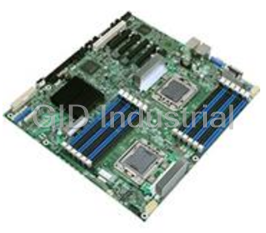
INTEL MB S5000PAL CPU BOARD - DUAL XEON 5000 5100 5300 SERIES 8-FBDIMMS SAS SATA
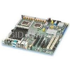
INTEL S5000PSLSAS CPU Boards-DUAL XEON 5000 5100 5300 SERIES W INTERGRATED 4-PORT SAS
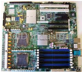
INTEL MB S5000PSLSATA CPU BOARD - DUAL XEON 5000 5100 SERIES 8-FBDIMMS 6SATA 3GBPS PORTS
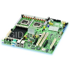
INTEL MB S5000VSA4DIMM PU BOARD - XEON 5000 5300 SERIES 4 FBDIMM SLOTS 6SATA PORTS
Request a Quote

The quote request has been received
Close

Facing challenges or have inquiries? Feel free to contact us!
Call Us +1-469-283-2440
What they say about us
FANTASTIC RESOURCE
One of our top priorities is maintaining our business with precision, and we are constantly looking for affiliates that can help us achieve our goal. With the aid of GID Industrial, our obsolete product management has never been more efficient. They have been a great resource to our company, and have quickly become a go-to supplier on our list!
Bucher Emhart Glass
EXCELLENT SERVICE
With our strict fundamentals and high expectations, we were surprised when we came across GID Industrial and their competitive pricing. When we approached them with our issue, they were incredibly confident in being able to provide us with a seamless solution at the best price for us. GID Industrial quickly understood our needs and provided us with excellent service, as well as fully tested product to ensure what we received would be the right fit for our company.
Fuji
HARD TO FIND A BETTER PROVIDER
Our company provides services to aid in the manufacture of technological products, such as semiconductors and flat panel displays, and often searching for distributors of obsolete product we require can waste time and money. Finding GID Industrial proved to be a great asset to our company, with cost effective solutions and superior knowledge on all of their materials, it’d be hard to find a better provider of obsolete or hard to find products.
Applied Materials
CONSISTENTLY DELIVERS QUALITY SOLUTIONS
Over the years, the equipment used in our company becomes discontinued, but they’re still of great use to us and our customers. Once these products are no longer available through the manufacturer, finding a reliable, quick supplier is a necessity, and luckily for us, GID Industrial has provided the most trustworthy, quality solutions to our obsolete component needs.
Nidec Vamco
TERRIFIC RESOURCE
This company has been a terrific help to us (I work for Trican Well Service) in sourcing the Micron Ram Memory we needed for our Siemens computers. Great service! And great pricing! I know when the product is shipping and when it will arrive, all the way through the ordering process.
Trican Well Service
GO TO SOURCE
When I can't find an obsolete part, I first call GID and they'll come up with my parts every time. Great customer service and follow up as well. Scott emails me from time to time to touch base and see if we're having trouble finding something.....which is often with our 25 yr old equipment.
ConAgra Foods