

 Manufacturers
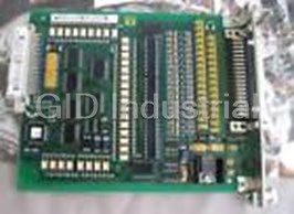
INDRAMAT DEA04.1
Description
Indramat DEA04.1 - Input / Output Interface
Part Number
DEA04.1
Price
Request Quote
Manufacturer
INDRAMAT
Lead Time
Request Quote
Category
PRODUCTS - D
Specifications
Input Channel
15
Output Channel
16
Datasheet

Extracted Text
engineering mannesmann Rexroth DIAX02 DDS02.1/03.1 Drive Controller - Basic Unit Project Planning Manual DOK-DIAX02-DDS02.1/3.1-PRJ1-EN-P 274262 Indramat DDS02.1/03.1 Title DIAX02 DDS02.1/03.1 Drive Controller - Basic Unit Type of documentation Project Planning Manual Document code DOK-DIAX02-DDS02.1/3.1-PRJ1-EN-E1,44 • 04.97 Internal file reference • Mappe 11a • DDS_1-PJ.pdf • 209-0069-4317-02 Reference This electronic document based on the hardcopy document with docu- ment desig.: DOK-DIAX02-DDS02.1/3.1-PRJ1-EN-P. Editing sequence Document designation of previous edi- Status Comments tions 209-0069-4317-01 EN/12.93 Dec. 93 1st edition DDS02.1 209-0069-4362-00 EN/01.94 Jan. 94 1st edition DDS03.1 DOK-DIAX02-DDS02.1/3.1-PRJ1-EN-P Jan. 97 rev. edition DDS02.1/03.1 DOK-DIAX02-DDS02.1/3.1-PRJ1-EN-E1,44 Apr. 97 E-Doc Release Copyright INDRAMAT GmbH, 1993 Copying this document, and giving it to others and the use or communi- cation of the contents thereof without express authority are forbidden. Offenders are liable for the payment of damages. All rights are reserved in the event of the grant of a patent or the registration of a utility model or design (DIN 34-1). The electronic documentation (E-doc) may be copied as often as needed if such are to be used by the consumer for the purpose intended. Published by INDRAMAT GmbH • Bgm.-Dr.-Nebel-Str. 2 • D-97816 Lohr a. Main Telefon 09352/40-0 • Tx 689421 • Fax 09352/40-4885 Abt. ENA (JH) Service-Hotline: Tel. 0172 - 660 040 6 or 0171 - 333 882 6 Validity All rights are reserved with respect to the content of this documentation and the availability of the product. DOK-DIAX02-DDS02.1/3.1-PRJ1-EN-E1,44 • 04.97 DDS02.1/03.1 Contents 1 Introducing the System 1-1 1.1 Individual components of the digital AC servo drive.............................................................................1-2 1.2 Supply units for DDS02.1/03.1 drive controllers...................................................................................1-2 2 Safety guidelines for electrical drives 2-1 2.1 General information..............................................................................................................................2-1 2.2 Guidelines for protection against contact with electrical parts .............................................................2-1 2.3 Guidelines on "protective low voltages" ...........................................................................................2-3 2.4 Guidelines for protection against dangerous movements....................................................................2-3 2.5 Guidelines for protection when handling and installing ........................................................................2-5 3 DDS02.1/03.1 drive controllers 3-1 3.1 Configured drive controllers .................................................................................................................3-1 3.2 Drive controller, basic unit....................................................................................................................3-4 Cooling methods............................................................................................................................3-4 Motor feedback..............................................................................................................................3-4 3.3 Software module ..................................................................................................................................3-7 Firmware........................................................................................................................................3-7 3.4 Firmware configuration.........................................................................................................................3-9 3.5 Plugin module.....................................................................................................................................3-10 3.6 Configuration rating plate ...................................................................................................................3-12 3.7 Summary of components fitted in a configuration..............................................................................3-13 4 Technical data 4-1 4.1 Power section.......................................................................................................................................4-1 4.2 Current consumed during signal processing........................................................................................4-2 4.3 Ambient and environmental conditions ................................................................................................4-4 4.4 Drive controller energy loss..................................................................................................................4-5 Energy loss in the DDS02.1-W......................................................................................................4-5 Energy loss in the DDS02.1-A.......................................................................................................4-6 Energy loss in the DDS02.1-F... ....................................................................................................4-7 Energy loss in the DDS03.1-W......................................................................................................4-8 4.5 Weight ..................................................................................................................................................4-8 5 Planning the construction of the control cabinet 5-1 5.1 Mounting the DDS02.1-W... drive controller.........................................................................................5-4 5.2 Mounting the DDS02.1-A... drive controller..........................................................................................5-5 5.3 Mounting the DDS02.1-F... drive controller........................................................................................5-10 5.4 Mounting the DDS03.1-W...-. drive controller ....................................................................................5-12 DOK-DIAX02-DDS02.1/3.1-PRJ1-EN-E1,44 • 04.97 Contents I DDS02.1/03.1 5.5 Interference suppression and EMC....................................................................................................5-13 5.6 Using heat-exchanger units in control cabinets .................................................................................5-13 6 Electrical connections of the drive controller 6-1 6.1 General notes.......................................................................................................................................6-1 6.2 Connecting the basic unit.....................................................................................................................6-2 � Chassis earth connections to the supply unit ............................................................................6-4 ��� Connecting the motor power cable to the drive controller...................................................6-4 � Connector X6: Holding brake, motor temperature monitoring..................................................6-7 � DC bus voltage connection........................................................................................................6-7 � Connector X1: Bus connections ................................................................................................6-8 � Connector X3.............................................................................................................................6-9 � Connector X2: interface RS232...............................................................................................6-11 � Connector X4: Motor feedback................................................................................................6-12 � Connectors X13, X14a, X14b: heatsink blower only with DDS02.1-A.....................................6-14 Summary terminal diagram .........................................................................................................6-15 6.3 Connecting the plugin module............................................................................................................6-16 7 Accessories 7-1 7.1 Electrical connecting kit E..-DDS 2.......................................................................................................7-2 7.2 Electrical accessories kit E..-DDS 3.....................................................................................................7-4 7.3 Connector kit for various configurations...............................................................................................7-6 7.4 Service cable - IKS0391.......................................................................................................................7-7 7.5 Selecting the fiber optic cable connections ..........................................................................................7-7 7.6 Mechanical accessories for DDS02.1-A***-*........................................................................................7-8 7.7 Mechanical accessories for DDS02.1-F***-* drive controllers (with liquid cooling) ..............................7-9 8 Powering up the power sections via charging resistors 8-1 9 Condition at delivery 9-1 10 Identifying the merchandise 10-1 11 Storage and transportation 11-1 12 Index 12-1 DOK-DIAX02-DDS02.1/3.1-PRJ1-EN-E1,44 • 04.97 Contents II DDS02.1/03.1 1 Introducing the System Inductance linear motor LAF Inductance linear motor LAR Synchronous motor MKD Synchronous motor MDD UBERSICH.WMF Fig. 1-1: A digital drive system with DDS The modular concept makes it possible to flexibly combine AC servo and main drives to create one compact drive package which uses one supply unit. In conjunction with the MDD, MKD and LAR AC motors, the DDS drive controller is a rapid-response drive. These drives are particularly well suited for use in machine tool, textile, printing and packaging machinery as well as robotics and handling machines. DOK-DIAX02-DDS02.1/3.1-PRJ1-EN-E1,44 • 04.97 Introducing the System 1-1 X8 S1 A1 A2 A3 L- L+ X1 1 11 DDS02.1/03.1 1.1 Individual components of the digital AC servo drive electrical connect access. plugin module configured drive controller Motor feedback cable Motor power cable AC motor EKdig Fig. 1-2: Individual components of the digital AC drive 1.2 Supply units for DDS02.1/03.1 drive controllers DDS drive controllers can be connected to all INDRAMAT supply units with a regulated DC 24V voltage. Note: Do not operate the DDS with a TVM 1.2 supply unit. The DC 24V of the TVM 1.2 is not regulated. If TVM 2.1, TVM 2.4 supply units or a KDV 1.3 are used with a DDS drive controller, then note the information in Section 8 when powering up the power section via charging resistors. The application descriptions for each individual supply units must also be noted. DOK-DIAX02-DDS02.1/3.1-PRJ1-EN-E1,44 • 04.97 Introducing the System 1-2 DDS02.1/03.1 2 Safety guidelines for electrical drives Prior to using the units, please note the following guidelines on personnel safety. 2.1 General information • The safety instructions in these user guidelines must be observed at all times. Improper use of this equipment and disregarding the war- nings given here can lead to property damage, cause bodily injury or, in extreme cases, lead to death. INDRAMAT is not liable for damages resulting from non-observance of the warnings given in these operating instructions. • Documentation in the local language must be obtained prior to com- missioning, if the language of the documentation at hand is not un- derstood. • Proper transport, correct storage, assembly and installation as well as careful operation are the prerequisites for optimal and safe operation of this equipment. • Qualified personnel: Only appropriately qualified personnel may work on this equipment or within its vicinity. Personnel are qualified if they have sufficient know- ledge of the assembly, installation and operation of the product as well as of all warnings and safety measures in these operating instructions. Furthermore, they should be trained, instructed or qualified to switch electrical circuits and equipment on and off, to earth and label them according to engineering regulations on safety. They should have ade- quate safety equipment and be trained in first aid. • Only use spare parts approved by the manufacturer. • The safety instructions and regulations for the application must be ob- served. • The equipment is designed for installation in machines which are in- tended for commercial use. • Start-up is only permitted once it is sure that the machine in which the products are installed complies with EC directive 89/392/EWG (machine directives). • Operation is only permitted if the national EMC directives for the spe- cific application permit it. Within the EU, EMC directive 89/336/EWG applies. Guidelines for EMC compliant installation are outlined in the document "EMC for AC drives and controls“. Maintaining the national standards is the responsibility of the manu- facturer of the machine or plant. • Technical data, connection and installation conditions are outlined in the respective product documentation and must be maintained. 2.2 Guidelines for protection against contact with electrical parts If live parts with voltages exceeding 50 volts are in any way open to con- tact, then this could lead to bodily injury. To operate electrical equipment it is necessary to apply certain parts of it with such dangerous voltages. DOK-DIAX02-DDS02.1/3.1-PRJ1-EN-E1,44 • 04.97 Safety guidelines for electrical drives 2-1 DDS02.1/03.1 High electrical voltages! Danger to life and risk of injury! ⇒ Observe the general construction and safety guideli- nes for work on electrial power installations. DANGER ⇒ After installation, check that the earth wire is perma- nently connected to all electrical units as specified in the connection diagram. ⇒ Operation, even for brief measuring and test purpo- ses, is only permitted when the earth wire is perma- nently connected to all electrical components. ⇒ Disconnect the equipment from the mains or the vol- tage source before working on electrical parts with voltages exceeding 50 volts. Secure the equipment against being switched back on again. ⇒ Wait five minutes after powering down before starting work on the equipment. This is due to the capacitors fitted in the equipment. ⇒ Do not touch the electrical connecting points of a component while it is switched on. ⇒ Cover live parts properly before switching the equip- ment on so that no contact is possible. ⇒ Provide protection against indirect contact (as per DIN EN 50178/ ed. 11/94, section 5.3.2.3). High discharge current! Danger to life and risk of serious injury! ⇒ All units and the motor are to be connected to the earth wire at the earthable point or they must be eart- WARNING hed first before switching on. ⇒ The discharge current exceeds 3.5 mA. A permanent connection to the supply system is thus required for all units (as per DIN EN 50178/ ed. 11.94, sect. 5.3.2.3). ⇒ Always connect earth wire before starting up even when just testing. High voltages could otherwise be applied to the housing. DOK-DIAX02-DDS02.1/3.1-PRJ1-EN-E1,44 • 04.97 Safety guidelines for electrical drives 2-2 DDS02.1/03.1 2.3 Guidelines on "protective low voltages" The connections on the drive components and interfaces for the signal voltages range from 5 to 30 volts. These electrical circuits belong to the safely isolated electrical circuits (protective low voltages). High electrical voltages from incorrect connections! Danger of life and limb or serious bodily injury! ⇒ Only those units, electrical components or cables WARNING which have, as per the standards, sufficient and safe isolation of connected electrical circuits may be atta- ched to the signal voltages (per DIN EN 50178/ ed. 11.94, sect. 5.3.2.3). 2.4 Guidelines for protection against dangerous movements Dangerous movements can occur for various reasons: • as a result of an incorrect velocity command, • a software error, • physical component problems, • faulty wiring or cable, • an error in the value or signal encoder and • incorrect use of components. These errors can occur just after the equipment is turned on or after an indefinite period of time. DOK-DIAX02-DDS02.1/3.1-PRJ1-EN-E1,44 • 04.97 Safety guidelines for electrical drives 2-3 DDS02.1/03.1 Dangerous movements! Danger to life and risk of injury or of property damage! ⇒ The drive components monitoring devices make mal- functions in the connected drives almost impossible. DANGER In view of operator safety, however, this cannot be solely relied upon. An incorrect movement, the size of which depends on the kind of malfunction and opera- ting status, must in any case be anticipated before the built-in monitoring devices are activated. Operator safety must thus be ensured with the use of monito- ring devices or measures taken which are superordi- nate on the plant side. These are provided according to the specific conditions of the plant after a danger and error analysis by the plant constructor has been completed. The safety requirements which apply to the plant are included here. ⇒ Keep clear of the machine in that area in which mo- vements could occur. Possible measures to take to prevent access are: - protective fences - protective railings - covers - light curtains ⇒ Fences and coverings should have sufficient strength to withstand the maximum possible momentum. ⇒ E-stop switches must be mounted in the immediate vicinity of an operator for easy reach. Check to make sure it is functional before starting up. ⇒ Isolate the drive power connection via an emergency stop circuit or use a starting lockout to protect against unintentional start ups. ⇒ Make sure that the drives are standing still before ac- cessing or entering the danger zone. ⇒ De-energize electrical equipment using the master switch and secure against switching on again for: - maintenance and repair work - cleaning work - or prior to long breaks in operation ⇒ Avoid operating high-frequency, remote control and radio equipment near the equipment electronics and supply leads. If use of such a unit cannot be avoided, check the system and the plant for possible malfuncti- ons at all positions of normal use before the first star- tup. If necesesary, carry out a special EMC test on the plant. DOK-DIAX02-DDS02.1/3.1-PRJ1-EN-E1,44 • 04.97 Safety guidelines for electrical drives 2-4 DDS02.1/03.1 2.5 Guidelines for protection when handling and installing Risk of injury during handling! Bodily injury caused by cruhsing, shearing, cutting and thrusting movements! CAUTION ⇒ Observe the general construction and safety regulati- ons for handling and installation. ⇒ Use suitable installation and transport equipment in a proper fashion. If necessary, use special tools. ⇒ Take suitable precautions to prevent pinching and crushing. ⇒ If necessary, wear suitable protective clothing, for ex- ample, protective eyewear, shoes or gloves. ⇒ Do not stand under suspended loads. ⇒ Wipe up liquids spilled onto the floor to prevent slip- ping. DOK-DIAX02-DDS02.1/3.1-PRJ1-EN-E1,44 • 04.97 Safety guidelines for electrical drives 2-5 7 7 6 6 5 5 4 4 3 3 DDS02.1/03.1 3 DDS02.1/03.1 drive controllers 3.1 Configured drive controllers The drive controllers are modular in design. The basic unit is adapted to different functions with the use of various modules. The drive controllers are delivered by INDRAMAT already configured in terms of the desired function. A configured drive controller is made up of both hardware and firmware. The firmware fixes the functions of the drive controller. A configured drive controller is made up of: • basic unit of the drive controller • plugin modules • software modules Configured DDS02.1-****-****-**- • firmware (in the software and plugin modules) FW drive controller Drive controller basic unit 1 Firmware configuration rating plate 6 S1 A1 H1 FWA-DIAX02-SSE-02VRS-MS 269236 K42/96 SN269236-02328 RS U5 SYSTEMCONFIGURATION DDS02.1-W100-DS04-03-FW L+ DDS02.1-W100-D U X5 DSS01.3 1 U DLF01.1 2 DDS 02.1-W025-D rating plate K16/96 U COVER 3 basic unit SN263498-24321 A01 X1 U COVER 4 U DSM02.1-FW 5 U1 U2 U3 U4 269973 K47/96 ATTENTION Achtung X3 THE CONFIGURATION Hier muß das TYPE STICKER, WHICH korrekte IS IN ACCORDANCE Typenschild 1 WITH THE CONFIGU- gemäß RATION SHEET, MUST Konfigurationsblatt aufgeklebt sein BE PLACED HERE. 11 X4 Hardware configuration rating plate EKkonfDD Fig. 3-1: The components of the configured DDS02.1-*** drive controller DOK-DIAX02-DDS02.1/3.1-PRJ1-EN-E1,44 • 04.97 DDS02.1/03.1 drive controllers 3-1 U5 Soft- ware- modul 2 2 command communi- cation module U1 U2 U3 U4 aux. plugin module 1 1 0 0 9 9 8 8 7 7 6 6 5 5 4 4 3 3 DDS02.1/03.1 Configured DDS03.1-****-****-**- FW drive controller Drive controller basic unit 1 X6 Firmware configuration rating plate U5 6 S1 H1 FWA-DIAX02-SSE-02VRS-MS 269236 K42/96 X5a SN269236-02328 RS SYSTEMCONFIGURATION DDS03.1-W030-DS01-02-FW L- DDS03.1-W030-D U DSS 1.3 L+ 1 U COVER 2 U COVER 3 X5b U rating plate COVER 4 U basic unit DSM02.1-FW 5 DDS 3.1-W030-D K30/95 269973 K47/96 X1 SN263508-04604 A00 U1 U2 ATTENTION Achtung THE CONFIGURATION Hier muß das TYPE STICKER, WHICH korrekte X2 IS IN ACCORDANCE Typenschild WITH THE CONFIGU- gemäß RATION SHEET, MUST Konfigurationsblatt BE PLACED HERE. aufgeklebt sein X3 Hardware X4 configuration rating plate ekkonfd3 Fig. 3-2: The components of the configured DDS03.1-*** drive controller DOK-DIAX02-DDS02.1/3.1-PRJ1-EN-E1,44 • 04.97 DDS02.1/03.1 drive controllers 3-2 Soft- ware- modul 2 2 Command communi- cations module aux. plugin module U5 U1 U2 1 1 0 0 9 9 8 8 DDS02.1/03.1 Type codes Type codes DDS XX . 1 - X XXX - X X XX - XX - FW Example: Product group DDS DDS Series 202 303 Version 11 Cooling Air, control cab. int. air (extern) A 3 Coolant F 3 Air, control cab. ext. air (intern)W Rated current 15A 015 1 25A 025 1 30A 030 2 50A 050 100A 100 3 150A 150 3 200A 200 3 Motor feedback Digital servo feedback D Resolver feedback R Communications module ANALOG interface A INTERBUS-S interface C Single-axis pos. control L SERCOS interface S Function i.d. determined and documented by INDRAMAT e.g.: 01 01 Function i.d. version determined and documented by INDRAMAT e.g.: 01 01 Firmware I.d. that firmware is ordered as separate subitem FW Comment: 1 only for series "02" and cooling "W" 2 only for series "03" 3 only for series "02" TLDDS2 Fig. 3-3: Type codes of the configured DDS drive controller DOK-DIAX02-DDS02.1/3.1-PRJ1-EN-E1,44 • 04.97 DDS02.1/03.1 drive controllers 3-3 DDS02.1/03.1 3.2 Drive controller, basic unit The slots of the basic unit are empty. Cooling methods INDRAMAT offers various cooling methods for the DDS02.1 drive control- lers (see Fig. 3-4) . Cooling methods: • heat technology (cooling airflow inside the control cabinet) • cold technology (cooling airflow outside the control cabinet) • liquid cooling Heat Technology Units implementing heat technology dissipate heat within the control cabi- net. Consequentially: • large control cabinet • air conditioning may be needed This requires the least amount of mounting and installation efforts. Cold technology, liquid cooling These units have the advantage that a large part of the heat is lost outsi- de the control cabinet. As a result, these units can be mounted in small cabinets or housing. Units with liquid cooling offer the additional advantage of regaining lost energy. Motor feedback There are, independent of the rated current, two types of drive con- trollers (basic units). Only motors with Digital Servo Feedback (DSF) can be connected to the one type and only motors with Re- solver feedback (RSF) (see Fig. 3-5 „Motor feedback“) can be connected at X4 of the other type. Note: When selecting the motor/controller combination make sure that the motor feedback data type codes of motor and drive controller agree. DOK-DIAX02-DDS02.1/3.1-PRJ1-EN-E1,44 • 04.97 DDS02.1/03.1 drive controllers 3-4 DDS02.1/03.1 Cooling methods power dissip. Mounting panel Heat technnology DDS 2.1 - W . . . power dissip. ca.20% ca.80% power dissip. Cold technology DDS 2.1 - K . . . control cabinet back power dissip. Mounting panel ca.20% DDS 2.1 - F . . . liquid cooling KUEHLART power dissip. ca. 80% Fig. 3-4: Cooling methods in DDS02.1 drive controller illustrated DOK-DIAX02-DDS02.1/3.1-PRJ1-EN-E1,44 • 04.97 DDS02.1/03.1 drive controllers 3-5 DDS02.1/03.1 Type codes Type codes DDS X . X - X XXX - X Example: Product group DDS DDS Series 2 02 303 Version 11 Cooling Air, from outside control cab. (extern) A 3 Coolant F 3 Air, from inside control cab. (intern)W Rated current 15A 015 1 25A 025 1 30A 030 2 50A 050 100A 100 3 150A 150 3 200A 200 3 Motor feedback Digital servo feedback D Resolver feedback R Comments: typgrdds 1 only for series "02" and cooling "W" 2 only for series "03" 3 only for series "02" Fig. 3-5: Type codes of the DDS basic unit DOK-DIAX02-DDS02.1/3.1-PRJ1-EN-E1,44 • 04.97 DDS02.1/03.1 drive controllers 3-6 DSM02.1-FW DDS02.1/03.1 3.3 Software module Different functions require different software modules. The software mo- dule contains both firmware and drive parameters. The software module needed depends on the selected hardware configuration and the functi- ons of the drive. The software module guarantees that if the unit needs to be replaced, the already entered parameters can be carried over to the new unit. Type codes shipping date unit type week/year FWA-DIAX02-SSE-02VRS-MS K42/96 part no. 269236 barcode SN269236-02328 RS serial number Firmware release status TYPFWA Fig. 3-6: Software module type codes Barcode Software Serial number module type DSM 2.1 FWC-DIAX02-SSE-02VRS-MS 266234 K35/96 Abbrev. DDSSER17 Firmware type Fig. 3-7: Rating plates on the software module Firmware The functional features of the drive controllers are fixed by the firmware. The firmware must be ordered as a separate item. This means that it is always possible to reorder the same firmware version. The firmware is continuously being updated to function more accurately without, however, changing the functions. This designation is indicated in the type code as the firmware release status. If new functions are added, then the index number of the firmware version is increased (see Fig. 3-8) . DOK-DIAX02-DDS02.1/3.1-PRJ1-EN-E1,44 • 04.97 DDS02.1/03.1 drive controllers 3-7 DDS02.1/03.1 Type codes FW C - DIAX02 - SSE - 02 V RS - MS Type codes Example: Category Firmware FW Class PCB C Product name Product: DIAX02 DIAX02 Firmware type (alpha-numeric) SERCOS interface SSE Firmware version (01...99) 02 02 Character of firmware Test version T Standard V Firmware Release Status (Update) The most current status is delivered. RS Language (abbrev. see INN 09.04, sect. 1-1) TYPFW multilingual MS Fig. 3-8: Firmware type codes DOK-DIAX02-DDS02.1/3.1-PRJ1-EN-E1,44 • 04.97 DDS02.1/03.1 drive controllers 3-8 DDS02.1/03.1 3.4 Firmware configuration The firmware configuration identifies which firmware is used in the confi- gured drive controller. This means that the firmware configuration is used to determine which firmware the software module has and, if applicable, which firmware is in a plugin module. The rating plate of the firmware configuration is on the face plate. FW A - DIAX02 - SSE - 02 V RS - MS Type codes Example: Category Firmware FW Class Product A Product name Product: DIAX02 DIAX02 Firmware type (alpha-numeric) SERCOS interface SSE Firmware version (01...99) 02 02 Character of firmware Test version T Standard V Firmware Release Status (Update) Updated version delivered. RS Language (abbreviation see INN 09.04, sect. 1-1) TYPFWAK Multilingual MS Fig. 3-9: Firmware configuration type codes shipping date unit type week/year FWA-DIAX02-SSE-02VRS-MS K42/96 part no. 269236 barcode SN269236-02328 RS serial number Firmware release status TYPFWA Fig. 3-10: Firmware configuration rating plate DOK-DIAX02-DDS02.1/3.1-PRJ1-EN-E1,44 • 04.97 DDS02.1/03.1 drive controllers 3-9 DDS02.1/03.1 3.5 Plugin module Only a few of the plugin modules are introduced below. The precise functions offered by a specific firmware verison are outlined in the re- spective function description. SERCOS interface Type: DSS01.1, DSS01.3 The plugin module "SERCOS interface DSS" makes it possible to operate the digital drive with SERCOS interface compatible controls via a fiber optic cable. It also offers inputs for evaluating reference switches, travel range limit switches and sensor inputs. ANALOG interface with Type: DAE01.1 incremental encoder emulator The plugin module "ANALOG interface with incremental encoder emula- tor" makes it possible to operate digital intelligent AC servo drives with conventional controls via an analog interface. It also contains control in- puts and signal outputs for communicating with a connected control and generates incremental encoder signals for use as actual position values. ANALOG interface with Type: DAA01.1 absolute encoder emulator The plugin module "ANALOG interface with absolute encoder emulator" makes it possible to operate digital intelligent AC servo drives with con- ventional controls via an analog interface. It also contains control inputs and signal outputs for communicating with a connected control and gene- rates actual position values which meet the SSI standard (synchronous serial interface). Single axis positioning module Type: DLC01.1, DLC02.1 The plugin module "single axis positioning module" expands the drive controller to create a standalone single axis positioning unit. This control can be programmed with up to 3000 program blocks. Each program block describes one motion sequence or a specific state of the inputs to be monitored or the outputs to be set. The DLC02.1 is functionally compati- ble with the DLC01.1. The DLC02.1, however, also has an additional in- terface to connect an INTERBUS-S module DBS02.2 . Interbus S Slave interface Type: DBS02.1 The interbus S slave interface DBS02.1 makes it possible to directly load speed values as per the DRIVECOM standard profile 21. Interbus-S-Slave Interface Type: DBS02.2 The interbus S slave interface DBS02.2 means that a DLC02.1 single positioning module can be connected which directly loads target positions as per DRIVECOM standard profile 22 and can handle the I/O level of the DLC. Command card Type: CLC-... The CLC-... command card supports the central control of the drive units for the implementation of the "electronic shaft“. DOK-DIAX02-DDS02.1/3.1-PRJ1-EN-E1,44 • 04.97 DDS02.1/03.1 drive controllers 3-10 DDS02.1/03.1 ARCNET coupler card Type. DAK01.1 The DAK01.1 plugin module is a stackable card for the CLC-D02... com- mand card and creates the interface to an ARCNET bus system. Input/output interface Type: DEA04.1, DEA05.1, DEA06.1 These plugin modules each have 15 inputs and 16 outputs via which the drive can exchange binary signals with a PLC. They are differentiated in terms of the address set. Incremental position interface Type: DEF01.1, DEF02.1 The plugin module "incremental position interface" supports the trans- mission of square wave signals for evaluating an external scale directly mounted to the moving machine component in the drive controller. They are differentiated in terms of the address set. High resolution position Type: DLF01.1 interface The plugin module "high resolution position interface" supports the transmission of sinusoidal signals for evaluating an external scale directly mounted to the moving machine component in the drive controller. Summing input interface Type: DSE01.1 The plugin module "summing input interface" makes two summing inputs available in addition to the differential input for a configuration with analo- gue interface. It is possible, via these summing inputs, to apply additional command values for the differential input at the analog interface. Gearwheel encoder interface Type: DZF01.1, DZF02.1 The plugin module „gearwheel interface“ supports the evaluation of the high-resolution main spindle position encoder. Note: The technical data and the terminal diagrams of the plugin modules can be found in the document "DIAX02 plugin modu- le for digital intelligent drive controllers". DOK-DIAX02-DDS02.1/3.1-PRJ1-EN-E1,44 • 04.97 DDS02.1/03.1 drive controllers 3-11 DDS02.1/03.1 3.6 Configuration rating plate The type designations are on the configuration rating plate: • the configured drive controller, • the basic unit, • the software module in slot U5 • and the plugin modules in slots U1 to U4. These type designations can be used to determine which components ought to be in which slots. In the event of a breakdown, the information on this plate can be used to quickly and efficiently obtain the correct replacement parts. Note: The configuration rating plate supplies information about which modules of the drive controllers are in place. Please check, prior to commissioning the controller, that the correct modules are in place. Note: When mounting the drive controller, the face plate is removed from the controller with the rating plate. Please make sure that the face plate is remounted to the drive controller from which it was removed. SYSTEMCONFIGURATION Configured drive controller DDS 02.1-W050-DS04-03-FW type Basic unit DDS 02.1-W050-D type U DSS 01.3-FW 1 U DLF 01.1 2 Slot Plugin module U COVER designation type 3 U COVER 4 Software U DSM 02.1-FW module 5 Configured drive Shipping date controller part no. 269421 K42/96 week/year COVER = no plugin module in slot TSDDS2.WMF Fig. 3-11: An example of a configuration rating plate DOK-DIAX02-DDS02.1/3.1-PRJ1-EN-E1,44 • 04.97 DDS02.1/03.1 drive controllers 3-12 DDS02.1/03.1 3.7 Summary of components fitted in a configuration Use this summary to identify which plugin module ought to be in a specific drive controller configuration. Compare the configuration in the summary with the type of the configured drive controller. If the suffix of the type designation agrees with a configuration in the summary, then the summary should list what is fitted into slots 1 through 4 of the basic unit. This summary is no selection list for available configurations. Configuration Basic unit Slot U1 Slot U2 Slot U3 Slot U4 Slot U5 DA01-01-FW DDS0*.1-****-D DAE01.1 COVER COVER COVER DSM02.1-FW DA02-01-FW DDS0*.1-****-D DAA01.1 COVER COVER COVER DSM02.1-FW DA03-01-FW DDS0*.1-****-D DAE01.1 DEA04.2 COVER COVER DSM02.1-FW DA06-01-FW DDS0*.1-****-D DAE01.1 DLF01.1 COVER COVER DSM02.1-FW DA07-02-FW DDS0*.1-****-D DAE01.1 DZF02.1 COVER COVER DSM02.1-FW DA10-01-FW DDS0*.1-****-D DAE01.1 DEF01.1 COVER COVER DSM02.1-FW DA11-01-FW DDS0*.1-****-D DAE01.1 DSE01.1 COVER COVER DSM02.1-FW DA12-01-FW DDS0*.1-****-D DAA01.1 DSE01.1 COVER COVER DSM02.1-FW DA14-01-FW DDS0*.1-****-D DAE01.1 DRF01.1 COVER COVER DSM02.1-FW DC01-01-FW DDS0*.1-****-D DBS02.1-FW COVER COVER COVER DSM02.1-FW DC02-01-FW DDS0*.1-****-D DBS02.1-FW DEA04.1 COVER COVER DSM02.1-FW DC03-01-FW DDS0*.1-****-D DBS02.1-FW DEA04.1 DEA05.1 COVER DSM02.1-FW DC04-01-FW DDS0*.1-****-D DBS02.1-FW DZF01.1 COVER COVER DSM02.1-FW DL01-01-FW DDS0*.1-****-D DLC01.1-FW DEA04.1 COVER COVER DSM02.1-FW DL02-01-FW DDS0*.1-****-D DLC01.1-FW DEA04.1 DEA05.1 COVER DSM02.1-FW DL03-01-FW DDS0*.1-****-D DLC01.1-FW DEA04.1 DEA05.1 DEA06.1 DSM02.1-FW DL04-01-FW DDS0*.1-****-D DLC01.1-FW DEA04.1 DEF01.1 COVER DSM02.1-FW DL05-01-FW DDS0*.1-****-D DLC01.1-FW DEA04.1 DEA05.1 DEF01.1 DSM02.1-FW DL08-01-FW DDS0*.1-****-D DLC01.1-FW DEA04.1 DFF01.1 COVER DSM02.1-FW DL09-01-FW DDS0*.1-****-D DLC01.1-FW DEA04.1 DEA05.1 DFF01.1 DSM02.1-FW DL10-01-FW DDS0*.1-****-D DLC01.1-FW DEA04.1 DEF01.1 DEF02.1 DSM02.1-FW DL11-01-FW DDS0*.1-****-D DLC01.1-FW DEA04.1 DZF01.1 COVER DSM02.1-FW DL12-01-FW DDS0*.1-****-D DLC01.1-FW DEA04.1 DEA05.1 DZF01.1 DSM02.1-FW DL13-01-FW DDS0*.1-****-D DLC01.1-FW DEA04.1 DEF02.1 DLF01.1 DSM02.1-FW DL14-01-FW DDS0*.1-****-D DLC01.1-FW DEA04.1 DLF01.1 COVER DSM02.1-FW DL20-01-FW DDS0*.1-****-D DLC02.1-FW DBS02.2-FW COVER COVER DSM02.1-FW DL21-01-FW DDS0*.1-****-D DLC02.1-FW COVER DBS02.2-FW COVER DSM02.1-FW DL22-01-FW DDS0*.1-****-D DLC02.1-FW DBS02.2-FW DEA04.1 COVER DSM02.1-FW DL23-01-FW DDS0*.1-****-D DLC02.1-FW DEA04.1 DBS02.2-FW COVER DSM02.1-FW DL24-01-FW DDS0*.1-****-D DLC02.1-FW DBS02.2-FW DEA04.1 DEA05.1 DSM02.1-FW DL25-01-FW DDS0*.1-****-D DLC02.1-FW DEA04.1 DBS02.2-FW DEA05.1 DSM02.1-FW DL26-01-FW DDS0*.1-****-D DLC02.1-FW DBS02.2-FW DEA04.1 DEF01.1 DSM02.1-FW DL27-01-FW DDS0*.1-****-D DLC02.1-FW DEA04.1 DBS02.2-FW DEF01.1 DSM02.1-FW DL28-01-FW DDS0*.1-****-D DLC02.1-FW DBS02.2-FW DFF01.1 COVER DSM02.1-FW DL29-01-FW DDS0*.1-****-D DLC02.1-FW DFF01.1 DBS02.2-FW COVER DSM02.1-FW DL30-01-FW DDS0*.1-****-D DLC02.1-FW DBS02.2-FW DEF01.1 COVER DSM02.1-FW DL31-01-FW DDS0*.1-****-D DLC02.1-FW DEF01.1 DBS02.2-FW COVER DSM02.1-FW DOK-DIAX02-DDS02.1/3.1-PRJ1-EN-E1,44 • 04.97 DDS02.1/03.1 drive controllers 3-13 DDS02.1/03.1 Configuration Basic unit Slot U1 Slot U2 Slot U3 Slot U4 Slot U5 DL40-01-FW DDS0*.1-****-D DLC01.1-FW DPF02.1 COVER COVER DSM02.1-FW DL41-01-FW DDS0*.1-****-D DLC01.1-FW DPF02.1 DEF01.1 COVER DSM02.1-FW DL42-01-FW DDS0*.1-****-D DLC01.1-FW DPF02.1 DFF01.1 COVER DSM02.1-FW DL43-01-FW DDS0*.1-****-D DLC01.1-FW DPF02.1 DPF03.1 COVER DSM02.1-FW DL45-01-FW DDS0*.1-****-D DLC01.1-FW DPF02.1 DEA05.1 COVER DSM02.1-FW DS01-02-FW DDS0*.1-****-D DSS01.3-FW COVER COVER COVER DSM02.1-FW DS03-02-FW DDS0*.1-****-D DSS01.3-FW DEF01.1 COVER COVER DSM02.1-FW DS04-03-FW DDS0*.1-****-D DSS01.3-FW DLF01.1 COVER COVER DSM02.1-FW DS05-01-FW DDS0*.1-****-D DSS01.1-FW DEF01.1 DEF02.1 COVER DSM02.1-FW DS06-02-FW DDS0*.1-****-D DSS01.1-FW DLF01.1 DFF01.1 CLC-D02.1A-FW DSM02.1-FW DS08-01-FW DDS0*.1-****-D DSS01.1-FW DLF01.1 DFF01.1 COVER DSM02.1-FW DS09-01-FW DDS0*.1-****-D DSS01.3-FW DFF01.1 COVER COVER DSM02.1-FW DS13-01-FW DDS0*.1-****-D DSS01.1-FW DLF01.1 COVER COVER DSM02.1-FW DS22-02-FW DDS0*.1-****-D DSS01.3-FW DLF01.1 DEA04.2 COVER DSM02.1-FW DS24-03-FW DDS0*.1-****-D DSS01.3-FW CLC-D02.1A-FW DEA04.2 COVER DSM02.1-FW DS25-01-FW DDS0*.1-****-D DSS01.1-FW DLF01.1 DSS02.1 COVER DSM02.1-FW DS37-01-FW DDS0*.1-****-D DSS01.3-FW DZF02.1 COVER COVER DSM02.1-FW DS40-02-FW DDS0*.1-****-D DSS01.3-FW DRF01.1 COVER COVER DSM02.1-FW DS41-00-FW DDS0*.1-****-D DSS01.3-FW CLC-D02.1A-FW COVER COVER DSM02.1-FW DS45-00-FW DDS0*.1-****-D DSS01.3-FW CLC-D02.1A-FW DEA04.2 DEA05.2 DSM02.1-FW DS46-00-FW DDS0*.1-****-D DSS01.3-FW CLC-D02.2A-FW DBS03.1-FW COVER DSM02.1-FW DS46-01-FW DDS0*.1-****-D DSS01.3-FW CLC-D02.2A-FW COVER DBS03.1-FW DSM02.1-FW DS47-00-FW DDS0*.1-****-D DSS01.3-FW CLC-D02.2A-FW DBS03.1-FW DLF01.1 DSM02.1-FW DS47-01-FW DDS0*.1-****-D DSS01.3-FW CLC-D02.2A-FW DLF01.1 DBS03.1-FW DSM02.1-FW DS48-00-FW DDS0*.1-****-D DSS01.1-FW DLF01.1 DEF02.1 COVER DSM02.1-FW DS50-00-FW DDS0*.1-****-D DSS01.3-FW CLC-D02.2A-FW DEA04.2 COVER DSM02.1-FW DS51-00-FW DDS0*.1-****-D DSS01.3-FW CLC-D02.2A-FW DEA04.2 DLF01.1 DSM02.1-FW DS51-01-FW DDS0*.1-****-D DSS01.3-FW CLC-D02.1A-FW DEA04.2 DLF01.1 DSM02.1-FW DS53-00-FW DDS0*.1-****-D DSS01.3-FW CLC-D02.1A-FW DEA04.2 DEF02.1 DSM02.1-FW DS54-00-FW DDS0*.1-****-D DSS01.3-FW DEA04.2 DEA05.2 COVER DSM02.1-FW DS55-00-FW DDS0*.1-****-D DSS01.3-FW DEF01.1 DEA04.2 COVER DSM02.1-FW DS56-00-FW DDS0*.1-****-D DSS01.3-FW DEA04.2 COVER COVER DSM02.1-FW DS57-00-FW DDS0*.1-****-D DSS01.3-FW CLC-D02.2A-FW DBS03.1-FW DEF01.1 DSM02.1-FW DS57-01-FW DDS0*.1-****-D DSS01.3-FW CLC-D02.2A-FW DEF01.1 DBS03.1-FW DSM02.1-FW DS58-00-FW DDS0*.1-****-D DSS01.3-FW CLC-D02.2A-FW DPF05.1-FW COVER DSM02.1-FW DS58-50-FW DDS0*.1-****-D DSS01.3-FW CLC-D02.2A-FW COVER DPF05.1-FW DSM02.1-FW DS59-00-FW DDS0*.1-****-D DSS01.3-FW CLC-D02.2A-FW DPF05.1-FW DLF01.1 DSM02.1-FW DS59-50-FW DDS0*.1-****-D DSS01.3-FW CLC-D02.2A-FW DLF01.1 DPF05.1-FW DSM02.1-FW DS60-00-FW DDS0*.1-****-D DSS01.3-FW CLC-D02.2A-FW DPF05.1-FW DEF01.1 DSM02.1-FW DS60-50-FW DDS0*.1-****-D DSS01.3-FW CLC-D02.2A-FW DEF01.1 DPF05.1-FW DSM02.1-FW DS61-00-FW DDS0*.1-****-D DSS01.3-FW DEA04.2 DEA05.2 DLF01.1 DSM02.1-FW RA01-02-FW DDS0*.1-****-R DAE01.1 COVER COVER COVER DSM02.1-FW RA02-02-FW DDS0*.1-****-R DAA01.1 COVER COVER COVER DSM02.1-FW RA11-01-FW DDS0*.1-****-R DAE01.1 DSE01.1 COVER COVER DSM02.1-FW RA12-01-FW DDS0*.1-****-R DAA01.1 DSE01.1 COVER COVER DSM02.1-FW RC01-01-FW DDS0*.1-****-R DBS02.1-FW COVER COVER COVER DSM02.1-FW RC02-01-FW DDS0*.1-****-R DBS02.1-FW DEA04.1 COVER COVER DSM02.1-FW RC03-01-FW DDS0*.1-****-R DBS02.1-FW DEA04.1 DEA05.1 COVER DSM02.1-FW RL01-01-FW DDS0*.1-****-R DLC01.1-FW DEA04.1 COVER COVER DSM02.1-FW RL02-01-FW DDS0*.1-****-R DLC01.1-FW DEA04.1 DEA05.1 COVER DSM02.1-FW DOK-DIAX02-DDS02.1/3.1-PRJ1-EN-E1,44 • 04.97 DDS02.1/03.1 drive controllers 3-14 DDS02.1/03.1 Configuration Basic unit Slot U1 Slot U2 Slot U3 Slot U4 Slot U5 RL03-01-FW DDS0*.1-****-R DLC01.1-FW DEA04.1 DEA05.1 DEA06.1 DSM02.1-FW RL04-01-FW DDS0*.1-****-R DLC01.1-FW DEA04.1 DEF01.1 COVER DSM02.1-FW RL05-01-FW DDS0*.1-****-R DLC01.1-FW DEA04.1 DEA05.1 DEF01.1 DSM02.1-FW RL08-01-FW DDS0*.1-****-R DLC01.1-FW DEA04.1 DFF01.1 COVER DSM02.1-FW RL09-01-FW DDS0*.1-****-R DLC01.1-FW DEA04.1 DEA05.1 DFF01.1 DSM02.1-FW RL10-01-FW DDS0*.1-****-R DLC01.1-FW DEA04.1 DEF01.1 DEF02.1 DSM02.1-FW RL20-01-FW DDS0*.1-****-R DLC02.1-FW DBS02.2-FW COVER COVER DSM02.1-FW RL21-01-FW DDS0*.1-****-R DLC02.1-FW COVER DBS02.2-FW COVER DSM02.1-FW RL22-01-FW DDS0*.1-****-R DLC02.1-FW DBS02.2-FW DEA04.1 COVER DSM02.1-FW RL23-01-FW DDS0*.1-****-R DLC02.1-FW DEA04.1 DBS02.2-FW COVER DSM02.1-FW RL24-01-FW DDS0*.1-****-R DLC02.1-FW DBS02.2-FW DEA04.1 DEA05.1 DSM02.1-FW RL25-01-FW DDS0*.1-****-R DLC02.1-FW DEA04.1 DBS02.2-FW DEA05.1 DSM02.1-FW RL26-01-FW DDS0*.1-****-R DLC02.1-FW DBS02.2-FW DEA04.1 DEF01.1 DSM02.1-FW RL27-01-FW DDS0*.1-****-R DLC02.1-FW DEA04.1 DBS02.2-FW DEF01.1 DSM02.1-FW RL28-01-FW DDS0*.1-****-R DLC02.1-FW DBS02.2-FW DFF01.1 COVER DSM02.1-FW RL29-01-FW DDS0*.1-****-R DLC02.1-FW DFF01.1 DBS02.2-FW COVER DSM02.1-FW RL30-01-FW DDS0*.1-****-R DLC02.1-FW DBS02.2-FW DEF01.1 COVER DSM02.1-FW RL31-01-FW DDS0*.1-****-R DLC02.1-FW DEF01.1 DBS02.2-FW COVER DSM02.1-FW RS01-03-FW DDS0*.1-****-R DSS01.3-FW COVER COVER COVER DSM02.1-FW RS03-03-FW DDS0*.1-****-R DSS01.3-FW DEF01.1 COVER COVER DSM02.1-FW RS04-03-FW DDS0*.1-****-R DSS01.3-FW DLF01.1 COVER COVER DSM02.1-FW RS16-02-FW DDS0*.1-****-R DSS01.3-FW DZF02.1 COVER COVER DSM02.1-FW RS18-02-FW DDS0*.1-****-R DSS01.3-FW DEA04.2 COVER COVER DSM02.1-FW Fig. 3-12: Summary of components of the basic units fitted in different configura- tions DOK-DIAX02-DDS02.1/3.1-PRJ1-EN-E1,44 • 04.97 DDS02.1/03.1 drive controllers 3-15 DDS02.1/03.1 4 Technical data 4.1 Power section DC bus voltage Designation Value Unit DC bus voltage 300 +/- 15% V Fig. 4-1: DC bus voltage Allocation of peak and An "overload factor" can be found in the motor/controller selection list. continuous currents Using this overload factor it is possible to set the continuous current of the controller at the time of commissioning in terms of the motor. The control- ler peak current is set as dependent upon the continuous controller cur- rent. In the second column, the possible continuous current is listed for the maximum peak current and in the third column, the possible peak current is given for the maximum continuous current in the following list. Drive controller Maximum peak cur- Peak current / ma- rent / continuous ximum continuous current current DDS02.1-W015-... 15A / 15A 15A / 15A DDS02.1-W025-... 25A / 25A 25A / 25A DDS03.1-W030-... 30A / 10A 15A / 15A DDS03.1-W050-... 50A / 20A 50A / 20A DDS02.1-W050-... 50A / 40A 50A / 40A DDS02.1-A050-... 50A / 50A 50A / 50 A DDS02.1-F050-... 50A / 50A 50A / 50A DDS02.1-W100-... 100A / 40A 60A / 60A DDS02.1-A100-... 100A / 80A 90A / 90A DDS02.1-F100-... 100A / 100A 100A / 100A DDS02.1-W150-... 150A / 65A 80A / 80A DDS02.1-A150-... 150A / 105A 150A / 105A DDS02.1-F150-... 150A / 105A 150A / 105A DDS02.1-W200-... 200A / 65A 90A / 90A DDS02.1-A200-... 200A / 85A 160A / 105A DDS02.1-F200-... 200A / 105A 200A / 105A Fig. 4-2: Allocating peak and continuous currents DOK-DIAX02-DDS02.1/3.1-PRJ1-EN-E1,44 • 04.97 Technical data 4-1 DDS02.1/03.1 4.2 Current consumed during signal processing Current consumed during The supply unit makes available the DC +24V - and DC +/- 15V - voltages signal processing for all connected drive controllers. The sum of the current consumed by all the controllers connected to the supply unit may not exceed the per- missible current output of the supply unit. Generally applicable for the current consumption of the drive controller is DC +/-15V ea. 200 mA , for DC +24V 1100 mA. For detailed calculations, the current consumption for one drive unit can be determined as follows: Current consumption of the basic unit + current consumption of the plugin module in the basic unit + current consumption of the motor feedback with MDD and MKD motors = current consumption for one drive unit Current consumption of the Controller ty- Current con- Current con- Current con- basic unit pes sumption DC sumption DC sumption DC +15V in mA -15V in mA +24V in mA DDS02.1-... 150 150 500 DDS03.1-... 150 150 500 Fig. 4-3: Current consumption of the basic unit Current consumption of the Use the type code of the motor to locate the designation of the motor motor feedback feedback. Motor feed- Current con- Current con- Current con- back sumption DC sumption DC sumption DC +15V in mA -15V in mA +24V in mA G25 5 0 K25 5 0 L0 0 40 M0 0 60 S0 0 40 T20 0 0 Fig. 4-4: Motor feedback current consumption DOK-DIAX02-DDS02.1/3.1-PRJ1-EN-E1,44 • 04.97 Technical data 4-2 DDS02.1/03.1 Current consumption of the Plugin module Current con- Current con- Current con- plugin modules type sumption DC sumption DC sumption DC +15V in mA -15V in mA +24V in mA CLC-D02.1A-FW 0 0 200 CLC-D02.2A-FW 0 0 200 DAA01.1 30 30 70 DAE01.1 30 30 70 DAK01.1A 0 0 70 DBS02.1-FW 0 0 130 DBS02.2-FW 0 0 130 DBS03.1-FW 0 0 130 DEA04.1 0 0 40 DEA04.2 0 0 40 DEA05.1 0 0 40 DEA05.2 0 0 40 DEA06.1 0 0 40 DEF01.1 0 0 150 DEF02.1 0 0 150 DFF01.1 45 45 45 DLC01.1 0 0 80 DLC02.1 0 0 80 DLC02.1-FW 0 0 80 DLF01.1 40 40 130 DPF05.1-FW 0 0 100 DRF01.1 50 50 15 DSE01.1 20 10 0 DSS01.1 0 0 110 DSS01.3-FW 0 0 110 DSS02.1 0 0 110 DZF01.1 30 40 150 DZF02.1 30 40 150 Fig. 4-5: Current consumption of the plugin module DOK-DIAX02-DDS02.1/3.1-PRJ1-EN-E1,44 • 04.97 Technical data 4-3 DDS02.1/03.1 4.3 Ambient and environmental conditions Designation Value Unit Permissible ambient temperature with rated data +0...+45 ºC Max. Permissible ambient temperature with derated data +55 ºC Storage and transport temperature -30...+85 ºC Max. Installation elevation with rated data 1000 m Max. Permissible relative air humidity 95 % 3 Max. Permissible absolute air humidity 25 g/m Protection category IP20, per EN 60529 = DIN VDE 0470-1-1992 (IEC 529-1989) Fig. 4-6: Ambient and environmental conditions Deviating ambient conditions Selection data are listed for each motor/controller combination. These data apply within the indicated ambient temperature and installati- on elevations. If conditions differ, then the continuous torque at standstill M and short- dN term torque MKB drop as illustrated. If both occur simultaneously, then both load factors must be multiplied. Reduction factor of the torque indicated in the selection lists Depends on Depends on ambient 1 temperature installation elev. 1 0.8 0.6 0.8 0.6 40 45 50 55 0 1000 2000 3000 4000 5000 Ambient temperature in °C Installation elev. in m above sea level umgetemp.fh5 Fig. 4-7: Load capacitiy as dependent on ambient temperature and installation elevation DOK-DIAX02-DDS02.1/3.1-PRJ1-EN-E1,44 • 04.97 Technical data 4-4 Reduction factor f T Reduction factor f H DDS02.1/03.1 4.4 Drive controller energy loss Determining energy loss in the controller by adding the maximum energy loss to the controller type does not account for the actual continous load of the controller. Over an average period of time, the maximum amount of the continuous current at standstill IdN of the motor flows through the controller (see motor documentation). The actually resulting energy loss depends on the continuous current at standstill IdN of the connected motor. The continous current at standstill IdN is listed in the motor documentation. Example: determining energy Controller: DDS 2.1 - W050 - … loss Motor: MDD 093A-N-020-… Standstill current I of the motor: 9.5A dN Energy loss as determined in Fig. 4-8: approx.. 80 W Energy loss in the DDS02.1-W... Energy loss in the control cabinet 600 max. energy loss Drive controller 560 DDS 2.1-W200-... 500 DDS 2.1-W150-... 440 400 380 DDS 2.1-W100-... 300 260 DDS 2.1-W050-... 200 170 DDS 2.1-W025-... 110 DDS 2.1-W015-... 100 10 20 30 40 50 60 70 80 90 DGVERLIN Cont. current at standstill of motor I in A dN Fig. 4-8: Determining the energy lost in the control cabinet DOK-DIAX02-DDS02.1/3.1-PRJ1-EN-E1,44 • 04.97 Technical data 4-5 Power dissipation P in W v DDS02.1/03.1 Energy loss in the DDS02.1-A... Energy loss in the control max. power dissip. Drive controllers cabinet 120 DDS 2.1-A200-... 120 DDS 2.1-A150-... 100 97 DDS 2.1-A100-... 80 60 54 DDS 2.1-A050-... 40 20 20 40 60 80 100 120 PVDDS2A Motor cont. curr. at standstill I in A dN Fig. 4-9: Determining the energy lost in the control cabinet Energy loss outside the control cabinet max. power dissip. Drive controllers 500 477 DDS 2.1-A200-... DDS 2.1-A150-... 400 380 DDS 2.1-A100-... 300 215 DDS 2.1-A050-... 200 100 20 40 60 80 100 120 PEXDDS2A Motor cont. curr. at standstill I in A dN Fig. 4-10: Determining the energy lost via the heatsink and conducted outside the control cabinet DOK-DIAX02-DDS02.1/3.1-PRJ1-EN-E1,44 • 04.97 Technical data 4-6 Power dissip. P in W Power dissip. P in W v v DDS02.1/03.1 Energy loss in the DDS02.1-F... Energy loss in the control max. power dissip. Drive controllers cabinet 120 120 DDS 2.1-F200-... DDS 2.1-F150-... 100 97 DDS 2.1-F100-... 80 60 54 DDS 2.1-F050-... 40 20 20 40 60 80 100 120 PVDDS2F Motor cont. curr. at standstill I in A dN Fig. 4-11:Determining energy lost in the control cabinet Energy loss via the coolant max. power loss Drive controllers 500 477 DDS 2.1-F200-... DDS 2.1-F150-... 400 DDS 2.1-F100-... 380 300 215 200 DDS 2.1-F050-... 100 PEXDDS2F 20 40 60 80 100 120 Motor cont. curr. at standstill I in A dN Fig. 4-12: Determining energy lost via the coolant DOK-DIAX02-DDS02.1/3.1-PRJ1-EN-E1,44 • 04.97 Technical data 4-7 Power dissip. P in W Power dissip. P in W v v DDS02.1/03.1 Energy loss in the DDS03.1-W... Energy loss in the control cabinet 150 max. power dissip. drive contr. type 140 DDS 3.1-W050-... 110 DDS 3.1-W030-... 100 50 5 10 15 20 DGViDDS3 Motor cont. current at standstill I in A dN Fig. 4-13: Determining energy lost in the control cabinet 4.5 Weight Drive controller type Weight in kg DDS02.1-W...-. (heat technology) approx. 7.5 DDS02.1-A...-. (cold technology) approx. 11 DDS02.1-F...-. (liquid cooling) approx. 11 DDS03.1-W...-. (heat technology) approx. 5.5 Fig. 4-14: Drive controller weight DOK-DIAX02-DDS02.1/3.1-PRJ1-EN-E1,44 • 04.97 Technical data 4-8 Power dissip. P in W v DDS02.1/03.1 5 Planning the construction of the control cabinet Mounting conditions The drive controller and its supply unit are designed for mounting into a control cabinet or a closed housing and meet the demands of protection category IP 10, as per DIN 40 050. The unit is protected against penetration by a solid extrinsic object with a diameter exceeding 50 mm. The unit is not protected against • penetration by water • intentional accessing by a hand, for example, but it will keep larger body surfaces out. Arranging the controller Position the drive with high output and excessive current levels as close to the supply unit as possible. Supply unit Controller with Controller with high output low output Mains conn. X5b ATTENTION! ATTENTION! NEVER REMOVE OR INSTALL THIS NEVER REMOVE OR INSTALL THIS ATTENTION! ATTENTION! PLUGS WHILE VOLTAGE IS APPLIED. NEVER REMOVE OR INSTALL THIS NEVER REMOVE OR INSTALL THIS PLUGS WHILE VOLTAGE IS APPLIED. BLACK CABLE ON THE BOTTOM! BLACK CABLE ON THE BOTTOM! PLUGS WHILE VOLTAGE IS APPLIED. PLUGS WHILE VOLTAGE IS APPLIED. Verbindung nie unter Spannung BLACK CABLE ON THE BOTTOM! BLACK CABLE ON THE BOTTOM! Verbindung nie unter Spannung lösen bzw. stecken. lösen bzw. stecken. Verbindung nie unter Spannung Verbindung nie unter Spannung Schwarze Leitung immer unten! lösen bzw. stecken. lösen bzw. stecken. Schwarze Leitung immer unten! Schwarze Leitung immer unten! Schwarze Leitung immer unten! GADDS3 Fig. 5-1: Recommended position of the unit inside the control cabinet DOK-DIAX02-DDS02.1/3.1-PRJ1-EN-E1,44 • 04.97 Planning the construction of the control cabinet 5-1 DDS02.1/03.1 Clearance dimensions DDS02.1 110 ±0,5 155 ±0,5 110 ±0,5 110 ±0,5 TVD DDS 2 TVD TDA DDS 2 DDS 2 KDV3 KDV3 KDA3.2 KDV4 KDV4 TVR3 TVR3 155 ±0,5 110 ±0,5 110 ±0,5 200 ±0,5 TVD DDS 2 TVD KDV2.2 TDA DDS 2 DDS 2 KDV3 KDV3 KDV2.3 KDA3.2 KDV4 KDV4 TVR3 TVR3 110 ±0,5 110 ±0,5 110 ±0,5 110 ±0,5 110 ±0,5 KVR 1 KVR 1 TVM DDS 2 DDS 2 DDS 2 2.1 2.4 60 GATeil Fig. 5-2: Clearance dimensions of the DDS02.1 within the control cabinet DOK-DIAX02-DDS02.1/3.1-PRJ1-EN-E1,44 • 04.97 Planning the construction of the control cabinet 5-2 DDS02.1/03.1 Clearance dimensions for 110 ±0,5 137 ±0,5 92 ±0,5 200 ±0,5 DDS03.1 TVD TDA DDS 3 DDS 3 TDA TVD KDV 3 KDA 3.2 KDA3.2 KDV3 KDV 4 KDV4 TVR 3 TVR3 92 ±0,5 74 ±0,5 155 ±0,5 DDS 3 TVD DDS 3 DDS 3 TVD KDV 3 KDV 3 KDV 4 KDV 4 TVR 3 TVR 3 110 ±0,5 92 ±0,5 92 ±0,5 110 ±0,5 KVR 1 DDS 3 DDS 3 KVR 1 92 ±0,5 92 ±0,5 92 ±0,5 DDS 3 TVM DDS 3 DDS 2 DDS 3 KDV 2.1 2.2 2.4 2.3 60 GATEDDS3 Fig. 5-3: Clearance dimensions for the DDS03.1 within the control cabinet DOK-DIAX02-DDS02.1/3.1-PRJ1-EN-E1,44 • 04.97 Planning the construction of the control cabinet 5-3 X8 S1 A1 A2 A3 L- L+ X1 1 11 DDS02.1/03.1 5.1 Mounting the DDS02.1-W... drive controller 13 7 air outlet 1 6 X6 S1 A1 A2 H1 A3 U5 L- L+ X5 X1 U1 U2 U3 U4 X2 X3 1 11 X4 8 15 9 1 air 7 inlet == 22.5 60 Machine screw M6 (DIN 912) (Allen screw) min. 40 mm free 325 Mounting panel or control cabinet back wall Allen screw driver 906q / SW 5x400-46185 Ident. no. 221 672 (avail. upon request) Tightening Connection MA torque A1 ; A2 ; A3 = M6 MA = 5 Nm L- ; L+ ; PE = M5 MA = 3 Nm Weight: approx. 7.5 MBDDS2W Fig. 5-4: Dimensional sheet - DDS02.1-W... DOK-DIAX02-DDS02.1/3.1-PRJ1-EN-E1,44 • 04.97 Planning the construction of the control cabinet 5-4 min. 80 mm min. 80 mm 355 Guard 17 (18) 105 390 373 8 DDS02.1/03.1 5.2 Mounting the DDS02.1-A... drive controller Drive controller mounted into the control cabinet Air baffle Power dissip. DDS2.•-A... heatsink ext. blower completely sealed housing or cabinet VerDDS2A Fig. 5-5: The DDS02.1-A... drive controller mounted in the control cabinet Power dissipation The DS02.1-A... drive controller has the advantage that most of the ener- gy lost by the unit is directly conducted outside thus not accumulating within the control cabinet. These units can therefore be mounted into small control cabinets or housing without requiring extensive heat con- ductance or expensive heat-exchanging units. Blower unit The electrical section of the blower is protected within the control cabinet (see Fig. 5-5). The heatsink of the power section and the blower impeller are outside the control cabinet or housing. Mounting panel Using a mounting panel, the units are mounted into the therefore provided space on the backwall of the cabinet in such a way that the heatsink with casing sticks out of the cabinet. The opening within the cabinet is sealed with a seal ring at the mounting flange of the unit after mounting (see Fig. 5-7). Mounting and exchange of the drive controller and external blower can be performed on the inside of the control cabinet. DOK-DIAX02-DDS02.1/3.1-PRJ1-EN-E1,44 • 04.97 Planning the construction of the control cabinet 5-5 intern extern DDS02.1/03.1 Dimensional sheet Fig. 5-6: Dimensional sheet of the DDS02.1-A... drive controller DOK-DIAX02-DDS02.1/3.1-PRJ1-EN-E1,44 • 04.97 Planning the construction of the control cabinet 5-6 325 160 105 1 6 X6 S1 A1 H1 A2 A3 U5 L- L+ X5 heatsink X1 U1 U2 U3 U4 X2 X3 1 11 X4 8 15 9 1 X13 X14a X14b Weight: approx. 11 kg Tightening Connection MA torque min. A1 ; A2 ; A3 = M6 MA = 5 Nm 40 mm free L- ; L+ ; PE = M5 MA = 3 Nm MBDDS2A min. 80 mm free min. 80 mm free 355 Guard 14 345 10 23 373 8 390 DDS02.1/03.1 Mounting plans - DDS02.1-A... MZDDS2A Fig. 5-7: Mounting the DDS02.1-A... drive controller DOK-DIAX02-DDS02.1/3.1-PRJ1-EN-E1,44 • 04.97 Planning the construction of the control cabinet 5-7 air baffle (1) M8 thread 69 space for additional KD modules machine screw / 4x M4x16 DIN912 (2) Note the conductive connection (2) contact disc M4/4x between back wall of control cabinet and mounting panel! KD module mounting frame (2) finger guard (1) Allen screw with SW5 blower mounting frame (1) M4 thread space for further blowers housing back wall housing and cabinet design machine screw / 2x M4x14Z4 DIN912 (1) Parts designated with (1) are in the blower. blower 109-0575-4832-XX (1) Parts designated with (2) are in the kit M1-KD. machine screw / 4x M4x18Z4-1 DIN912 (1) 185 DDS02.1/03.1 Installation dimensions - DDS02.1-A... min. 400 185 min. 2 air flow direction air guard 325 Mounting frame KD module heatsink 160 in KDS/KDV w/o ext.blower ext.blower dismantl. direction blow.motor completely sealed blower mounting frame housing or cabinet 110 min. 80 min. 80 KDV DDS 2.•-A... DDS 2.•-A... DDS 2.•-A... DDS 2.•-A... 18 105 X15 X15 X15 F6 F6 F6 fan EinDDS2A Fig. 5-8: Installation dimensions DOK-DIAX02-DDS02.1/3.1-PRJ1-EN-E1,44 • 04.97 Planning the construction of the control cabinet 5-8 174 min. 80 min. 200 355 69 421 DDS02.1/03.1 Spacing and clearance Control cabinet interior dimensions -DDS02.1-A... 110±0.5 110±0.5 110±0.5 4 x ø5 96±0,5 == 86+1 space space for further for units, DDS 2.• - A dimen. as unit 1 18 space for ext. blower == 92±0.2 GADDS2A 6 x ø5 92 Fig. 5-9: Spacing and clearance dimensions - DDS02.1-A ... DOK-DIAX02-DDS02.1/3.1-PRJ1-EN-E1,44 • 04.97 Planning the construction of the control cabinet 5-9 403±0.2 133±0.2 373±0.2 15 50+1 11 351+1 9 115 X8 S1 A1 A2 A3 L- L+ X1 1 11 DDS02.1/03.1 5.3 Mounting the DDS02.1-F... drive controller 325 min. 105 25 mm 13 free 7 1 6 X6 S1 A1 H1 A2 Back wall of A3 control cabinet U5 L- L+ Mounting X5 X1 U1 U2 U3 U4 X2 X3 1 11 X4 8 15 9 1 30 min. == 7 40 mm free 22.5 60 Opening for guard in panel 50 75 M5 75 Machine screw M6 (DIN 912) (Allen screw) Mounting panel or control cabinet back Weight: approx. 11 tightening Connection MA torque A1 ; A2 ; A3 = M6 MA = 5 Nm Allen screw driver L- ; L+ ; PE = M5 MA = 3 Nm 906q / SW 5x400-46185 Ident. no. 221 672 (avail. upon request) DDS21FMA Fig. 5-10: Dimensional sheet DDS02.1-F... drive controller DOK-DIAX02-DDS02.1/3.1-PRJ1-EN-E1,44 • 04.97 Planning the construction of the control cabinet 5-10 min. 80 mm min. 80 mm 355 Guard (18) 17 165 11 125 373 8 150 390 DDS02.1/03.1 Dimensional sheet of accessory kit SH-FL 82 70 Cover 2x M5x12 5.5 7 MBzub 50 Fig. 5-11: Dimensional sheet - SH-FL accessory kit Dimensional sheet approx. 50 (mounted) of accessory kit M2-F coupling SW 14 MBsteck SW 19 Fig. 5-12: Dimensional sheet - M2-F accessory kit Note: Please note the mounting and installation guidelines outlined in the document on "Liquid cooling Indramat drive compo- nents" (doc. no.: 209-0042-4131-00). DOK-DIAX02-DDS02.1/3.1-PRJ1-EN-E1,44 • 04.97 Planning the construction of the control cabinet 5-11 74 136 159 S1 A1 A2 A3 X1 1 11 DDS02.1/03.1 5.4 Mounting the DDS03.1-W...-. drive controller 325 70 13 7 air outlet max. 2 1.5mm 1 X6 6 U5 S1 2 max. 4mm H1 X5a L- L+ mounting panel X5b DDS 3.1-W030-D -------ENA K30/95 SN263508-04604 A00 X1 U1 U2 X2 max. 2 X3 1.5mm 1 11 X4 8 15 9 1 7 air inlet min. 40 mm free Tightening Connection MA Machine screw M6 (DIN 912) torque (Allen screw) L- ; L+ ; PE = M5 MA = 3 Nm Weight: approx. 5.5 Mounting panel or control cabinet back wall Allen screw driver 906q / SW 5x400-46185 Ident. no. 221 672 MBDDS3 (avail. upon request) Fig. 5-13: Dimensional sheet - DDS03.1-W...-. drive controller DOK-DIAX02-DDS02.1/3.1-PRJ1-EN-E1,44 • 04.97 Planning the construction of the control cabinet 5-12 min. 80 mm min. 80 mm 355 guard (18) 17 A3 A2 A1 373 8 390 DDS02.1/03.1 5.5 Interference suppression and EMC The mounting and installation guidelines in the Project Planning Manual on “EMC in drive and control systems” must be noted to maintain the le- gal EMC requirements. 5.6 Using heat-exchanger units in control cabinets If heat-exchanging units are not installed and operated properly, then the drive components inside the control cabinet could be damaged by moistu- re and condensation! Humid air penetrates the control cabinet and, when it cools, condenses DANGER from condense water onto the drive components installed in there. DANGER from condensation If the heat-exchanging unit is not located properly in the control cabinet, then the water constantly condensing on it can drip into the installed components or be sprayed into them by the cold air current. Avoiding moisture Proper use of heat-exchanging units: • Only use heat-exchanging units in well-sealed control cabinets so that moisture cannot be brought in by any humid outside air. • If the control cabinets are operated with opened doors, for startup, servicing and so on, then make sure, once the doors are closed, that the drive components are not at any time cooler than the air in the control cabinet. Moisture can otherwise occur. For this reason, the heat-exchanging unit must continue to operate even when the plant is switched off so that the temperature of the control cabinet air and the drive components installed remains at the same level. • Set heat-exchanger units with permanent temperature adjustment to 40 °C. not lower! • Set heat-exchanger units with temperature correction so that the insi- de temperature of the control cabinet is not lower than the outside air temperature. Set the limit to 40 °C! Avoiding dripping and spraying Always situate heat-exchanging units so that any condensation cannot water drip into the installed drive components. Heat-exchangers on the control cabinet roof require special control cabinet design! Design the control cabinet in such a way that the unit fan cannot spray condensation deposits onto the drive components after periods during which the unit was not operational! Summary • Make sure that no condensation drips from the heat-exchanging unit into the installed drive components! • Make sure the temperature is set correctly on the heat-exchanger unit! DOK-DIAX02-DDS02.1/3.1-PRJ1-EN-E1,44 • 04.97 Planning the construction of the control cabinet 5-13 DDS02.1/03.1 Heat-exchanger unit on the roof correct incorrect of the control cabinet cooling unit cooling unit warm cold warm cold air duct electronic electronic equipment equipment control cabinet control cabinet KDDDS2 Fig. 5-14: Arranging the heat-exchanger unit on the roof of the control cabinet Heat-exchanger unit on the correct incorrect front of the control cabinet control cabinet control cabinet air inlet air inlet air outlet air duct cooling cooling unit unit electronic electronic equipment equipment KFDDS2 Fig. 5-15: Arranging the heat-exchanger unit on the front of the control cabinet DOK-DIAX02-DDS02.1/3.1-PRJ1-EN-E1,44 • 04.97 Planning the construction of the control cabinet 5-14 DDS02.1/03.1 6 Electrical connections of the drive controller 6.1 General notes • The signal lines must be routed separately of the supply lines due to the interference. • All signal lines should use plugin clamps or D subminiature plugin connectors to facilitate any unit replacement that might be needed. • Analog signals must be routed via shielded leads and their shields mounted only to the drive controller. • Mains, DC bus and motor leads may not be permitted to come into contact with or be connected to the DC ±15V and DC +24V low volta- ges. • If a high or interference voltage test of the electrical equipment of the machine is to be conducted, then all connections must be clamped off or removed entirely to avoid damage to the electronic components (permissible per VDE 0113). The INDRAMAT drive components are tested in accordance with the VDE 0160 high-voltage test. • Electrostatic loads endanger electronic components. Body parts that come into contact with these components or printed circuits, must first be discharged by grounding. This means that the human body must be discharged by touching a grounded object, soldering iron and parts and tools must be placed on a conductive surface. • Endangered components such as plugin modules must be stored or transported in special packaging. • Maintaining limit values for the transmission of interference (noise re- duction) at the points of connection of the machine or plant, particularly when operating in residential or light industrial areas, requires a shiel- ded routing of the motor power cable or the use of a shielded motor power cable. Proper installation of an interference filter, as recom- mended by INDRAMAT, into the mains supply conductors of the ma- chine or plant is also advisable. The limit values as per class B (rf in- terference suppression grade N) as per EN 55011/3.91 and Table I per EN 55014/1987 at the machine must be maintained. Further in- formation can be found in the project planning manual „EMC in drive and control systems“ (doc. no: 209-0049-4305-..). DOK-DIAX02-DDS02.1/3.1-PRJ1-EN-E1,44 • 04.97 Electrical connections of the drive controller 6-1 DDS02.1/03.1 6.2 Connecting the basic unit Basic unit DDS02.1-... 3 ground conn. to 1 ground connection to 4 Motor the motor supply unit temperature monitor Motor brake connection DC +24V from external source Fault reset key Software module three-phase current of 2 the motor power cable 1 Status display warning and error messages 6 X6 S1 A1 6 Connection to adjacent DC bus connection 5 A2 unit with bus rails. H1 The connection starts The end plug supplied at the adjacent unit A3 with supply module via DC bus rails. must be inserted in U5 L- the final module (furthest distance). L+ X5 ATTENTION! NEVER REMOVE OR INSTALL THIS PLUGS WHILE VOLTAGE IS APPLIED. BLACK CABLE ON THE BOTTOM! Verbindung nie unter Spannung lösen bzw. stecken. Schwarze Leitung immer unten! X1 U1 U2 U3 U4 X2 X3 1 RS-232 interface 8 11 15 X4 VT-100 connection 8 - drive lockout connection Terminal or PC 7 9 - acknowledge drive lockout 1 - ready - 2 analog 9 diagnostic outputs motor feedback connection FADDS2GG 10 blower connection only with DDS02.1-A... Fig. 6-1: Front with designated connections for basic unit DDS02.1-... For details on points �...� see the following pages. DOK-DIAX02-DDS02.1/3.1-PRJ1-EN-E1,44 • 04.97 Electrical connections of the drive controller 6-2 1 2 3 DDS02.1/03.1 Basic unit DDS03.1-... Motor ground connection 4 1 temp. monitor. conn. to supply unit Motor brake conn. DC +24V from ext. source three-phase connection 2 Fault reset key of motor power cable ground conn. to 3 motor Software module 1 X6 Status display warning and error messages U5 6 S1 DC bus conn. 5 H1 Conn. to adj. unit 6 The conn. comes with bus rails. from adjacent unit The end plug in via DC bus rails. X5a the supply module acces. kit must be L- insert in final modular unit L+ (furthest distance). X5b ATTENTION! NEVER REMOVE OR INSTALL THIS PLUGS WHILE VOLTAGE IS APPLIED. BLACK CABLE ON THE BOTTOM! Verbindung nie unter Spannung lösen bzw. stecken. Schwarze Leitung immer unten! X1 U1 U2 - drive lockout control 7 X2 - acknowledge lockout - ready X3 RS-232 interface 8 - 2 analog diagnostic VT-100 connection outputs Terminal or PC 9 Motor feedback conn. X4 FADDS3GG Fig. 6-2: Front with connections designated of the basic unit DDS03.1-... For details on points �...� see the following pages. DOK-DIAX02-DDS02.1/3.1-PRJ1-EN-E1,44 • 04.97 Electrical connections of the drive controller 6-3 A3 A2 A1 DDS02.1/03.1 � � Chassis earth connections to the supply unit Ground connections VPErde Fig. 6-3: Chassis earth connection to the supply module Core cross section The cross section of the chassis earth connection • must be as big as the cross section of the mains supply line 2 • but not smaller than 10 mm Earth loops should be avoided, if possible, as intermeshing causes inter- ference and can make fault clearance more difficult. � �� �� � Connecting the motor power cable to the drive controller Use INDRAMAT motor power cables for the lines between the drive con- troller and the AC motors. Motor power cable The INDRAMAT motor power cable contains: • three lines for the motor power connection • one line for the protective conductor connection • a separately shielded pair of cables for motor temperature monitoring (PTC resistor in the motor) • a separately shielded pair of cables for the motor brake • a total shield for power cables IKG. Applies if being operated within residential or light industrial areas to maintain the limit values for the emission of interference (rf interference suppression). Otherwise, a totally shielded routing of the power supply may be necessary. The motor power cable is a ready-made cable and available from Indra- mat. A cable can also be made out of four individual leads (three phases, 1 protective conductor), with a separately conducted, shielded thermal resistance and brake connection cable. For further information on techni- cal data, connections and cross sections, please check the motor description and the cable catalog. Maximum cable length The maximum cable length equals 75 meters if INDRAMAT cables are used. DOK-DIAX02-DDS02.1/3.1-PRJ1-EN-E1,44 • 04.97 Electrical connections of the drive controller 6-4 DDS02.1/03.1 DDS02 motor power connection DDS 2.1 X6 A1 A2 A3 0VExt 24V 24VExt U MDD M servo motor 3 PTC holding brake Fig. 6-4: Motor power, holding brake and motor temperature monitoring con- nections in the DDS02.1 DDS02 power cable connection Motor power cable X6 shield 1) 1 5 or wh. TM+ 1) TM- 2 6 or br U 3 2) B 1) B 7 or red 4 R X6 1) 0V 5 8 or blk. B A1 S1 0V 6 2) B H1 A2 0V Ext. A3 U5 24V ±10% Ext. 1) The strands out of the motor power cable are numerically labelled. Exception: the strands of IN 253 are color coded. 2) External power source of holding brake equals: 24V direct voltage ±10%. 2 A cross section of at least 0.75 mm is recommended. DDS2SER Fig. 6-5: Motor power cable connection to the DDS02 DOK-DIAX02-DDS02.1/3.1-PRJ1-EN-E1,44 • 04.97 Electrical connections of the drive controller 6-5 A B C D 4 F BR 5 G 0VB 1 E TM+ 2 H TM- 3 UB 6 0VB SBX6DDS2 DDS02.1/03.1 DDS03 motor power cable connection DDS 3.1 X5 X6 0VExt 24V 24VExt U MDD M 3 Servo PTC Holding brake Fig. 6-6: Motor power, holding brake and motor temperature monitor connections with the DDS03.1 DDS03 power cable connections Motor power cable X6 Shield 1) 1 5 or wh. TM+ 1) TM- 2 6 or br 1 X6 U 3 2) B 1) B 7 or red 4 6 R 1) S1 0V 5 8or blk. B 0V 6 2) B H1 0V Ext. X5a U5 24V ±10% Ext. 1) The motor power cable cores are numerically identified. Exception: the cores of cable IN 253 are color coded. 2) The external power source of the holding brakes equals: 24V direct current ±10%. 2 A cross section of at least 0.75 mm is recommended. DDS3SER Fig. 6-7: Motor power cable connections to the DDS03 drive controller Connecting the power cable to In terms of the motor, the connection takes the form of either a connector the motor or terminal box. The DDS drive controller connections are outlined in the motor documen- tation as well as the circuitry with precise clamp designations. DOK-DIAX02-DDS02.1/3.1-PRJ1-EN-E1,44 • 04.97 Electrical connections of the drive controller 6-6 1 A A1 2 B A2 3 C A3 A3 A2 A1 4 D 4 F BR 5 G 0VB 1 E TM+ 2 H TM- 3 UB 6 0VB SBX6DDS3 DDS02.1/03.1 � � Connector X6: Holding brake, motor temperature monitoring It is only necessary to connect external DC 24V if a motor holding brake is used. The current consumption of the holding brake is listed in the motor docu- mentation. The holding brake of the MDD/MKD motors is not a service brake. It we- ars down after approximately 20,000 motor revolutions against the closed brake disc. Note: To release the holding brake it is necessary to apply DC +24V +/- 10 % directly to the motor. The voltage to release the motor brake is applied at X6/3 and X6/6. It must be certain that the brake will effectively release even if longer motor power cables are used (voltage drop with longer motor power cables can be compensated by higher voltages (to DC +28V) at X6/3 and X6/6). Controlling the motor holding The drive controller controls the motor holding brake. brake � � DC bus voltage connection Adjacent drive controllers are normally connected via the DC bus rails which are in the accessories kit E .. - DDS 2. If DC bus rails are not nee- ded for a specific connection, then the connection can be established via stranded leads that are as short as possible (maximum length of 1 me- ter). The cross section of the lead depends on the supply unit or the DC bus continuous output. DC bus rails must be used with the DDS02.1-.150-... and DDS02.1-.200- ... drive controllers. Supply unit DC bus continuous Lead cross section 2 ouput in kW in mm TVM 1.2-... 7.5 4 TVM 2.2-.../TVM 2.4-... 7.5 4 KDV 1.3-... 30 25 KDV 2.2-.../KDV 2.3-... 30 25 KDV 3.1-... 30 25 KDV 4.1-... 30 25 TVD 1.2-08-3 7.5 4 TVD 1.2-15-3 15 10 Fig. 6-8: DC bus connection - required cross sections DOK-DIAX02-DDS02.1/3.1-PRJ1-EN-E1,44 • 04.97 Electrical connections of the drive controller 6-7 DDS02.1/03.1 � � Connector X1: Bus connections The control electronics of the drive controllers are supplied via connector X1. The connection starts at the supply unit and runs to the drive control- lers with the help of the bus cable. The bus cable is part of the electrical connecting kit E . . -DDS 2. Insert the bus cable, with the black core at the bottom, into connector X1. Insert the end connector supplied in the kit (e.g.,: E3-TVD) of the supply unit into the last unit (the unit physically furthest away from the supply unit). In special cases it is possible to use a special bus cable with a maximum length of one meter. GVDDS3 supply unit mains end plug L- L- L+ L+ ATTENTION! ATTENTION! NEVER REMOVE OR INSTALL THIS PLUGS WHILE VOLTAGE IS APPLIED. NEVER REMOVE OR INSTALL THIS PLUGS WHILE VOLTAGE IS APPLIED. BLACK CABLE ON THE BOTTOM! Verbindung nie unter Spannung BLACK CABLE ON THE BOTTOM! Verbindung nie unter Spannung lösen bzw. stecken. Schwarze Leitung immer unten! lösen bzw. stecken. Schwarze Leitung immer unten! black strand of the bus conn. cable Fig. 6-9: Connecting the units via flat-ribbon cables and DC bus rails conn. X1 bus connection 1) 1 U D 1) 2 BB 1) "UD" - Signal: 3 +15V High = DC bus volt. 4 0V M UD exceeds 5 0V permissible M minimum 6 0V M value 7 0V M 8 -15V "BB" - Signal: 9 -15V High = drive module 10 0V ready 11 +24V 12 SBX1DDS2 Fig. 6-10: Connector assignment X1 DOK-DIAX02-DDS02.1/3.1-PRJ1-EN-E1,44 • 04.97 Electrical connections of the drive controller 6-8 DDS02.1/03.1 � � Connector X3 X3 1 AK1 2 Analog X2 OV M 3 diagnostic AK2 4 outputs 0V M 5 X3 6 ready Bb 7 to operate Bb contact 8 AS+ 9 AS- starting 10 ASQ lockout 11 ASQ X3 X4 SBX3DDS2 Fig. 6-11: Connector assignment X3 Analog diagnostic outputs AK1, The analog diagnostic outputs are analog outputs via which drive-internal AK2 variables are generated for test purposes, e.g., when commissioning. For further details on analog diagnostic outputs, please see the application description. Current load capacity: 4 mA Output voltage: DC 10 V Ready to operate contact Bb If ready to operate contact „Bb“ closes, then the drive controller is ready to receive power. The „Bb“ closes if the control voltage is on and all monito- ring functions are signalling a ready state. The „Bb“ can be evaluated in the control, for example, so that the control immediately recognizes which drive controller in the drive package has had a power failure. Switching capacity: DC 24 V, 1 A (short-term and continuous) Note: The direct connection of a contactor coil to the Bb contact is not permitted as the contact could be overloaded by excessive short-term currents after frequent switching sequences thus causing it to break down. The use of varistors as protective circuits is not acceptable as these require ever-higher levels of current over the course of their service life. This could cause early failures of the con- nected components and ultimately the unit as well. DOK-DIAX02-DDS02.1/3.1-PRJ1-EN-E1,44 • 04.97 Electrical connections of the drive controller 6-9 DDS02.1/03.1 Starting lockout The starting lockout represents a safety device to prevent unintentional AS+, AS-, ASQ, ASQ startups of the connected motors in the event of a fault. It makes sure that the separately working areas of a machine or plant are securely switched off. Note: The starting lockout is note intended to bring to a standstill axes that are moving. For further information on this topic, see the documentation on „Starting lockout - functions in drive controller DDS“ (doc. no: 209-0069-4313-XX). AS+,AS-: control input for relay coils voltage: DC 20 .... 30 V power: 1.5 W ASQ, ASQ: potential-free response contact which acknowledges the activation of a starting lockout to an external control. Switching power: DC 24 V, 1 A (short-term and continuous) To activate the starting lockout, apply a voltage of DC +20 ... 30 V betwe- en input terminsl AS+, AS-. The switching of the startup relay in the drive controller is confirmed by closing the potential-free response contact (output ASQ - ASQ) at the external control. DOK-DIAX02-DDS02.1/3.1-PRJ1-EN-E1,44 • 04.97 Electrical connections of the drive controller 6-10 DDS02.1/03.1 � � Connector X2: interface RS232 Service cable IKS0391 DDS 2.1 serial interface: V24, RS 232C connector X2 9-pin D-Submin. male 15 pin D-Submin. conn. X2 Signal Pin Signal Pin 8 15 3 TxD TxD 2 5 9 2 RxD RxD 3 RTS 7 1 RTS 4 1 8 CTS CTS 5 5 SGND SGND 7 DTR 4 6 DSR housing Order code: SBSKDDS2 (Example) IKS 0391/ . . . Cable length in meters 2, 5, 10 or 15m Fig. 6-12: Service cable Service cable IKS0391 is needed to commission drive controllers with ANALOG interface (configurations: DA..-..-FW and RA...-..-FW), as this interface is used for parametrization during startup with the use of a ter- minal / terminal program. DOK-DIAX02-DDS02.1/3.1-PRJ1-EN-E1,44 • 04.97 Electrical connections of the drive controller 6-11 DDS02.1/03.1 � � Connector X4: Motor feedback The motor feedback is connected at terminal X4. Independent of the rated current, there are two types of drive con- trollers (basic units). Digital Servo Feedbacks (DSF) only may be connected to motor feedback terminal X4, of the type, whilst only Resolver feedbacks (RSF) may be connected to the other. Pre-requisites: • The motors with a digital servo feedback (DSF) must be operated with DDSxx.1-xxxx-D drive controllers. • Motors with a resolver feedback (RSF) must be operated with DDSxx.1-xxxx-R drive controllers. Motor Drive controllers Drive controllers DDSxx.1-xxxx-D DDSxx.1-xxxx-R MDDxxxx-x-xxx-xxL-xxxx can be connected - MDDxxxx-x-xxx-xxM-xxxx can be connected - MDDxxxx-x-xxx-xxG-xxxx - can be connected MDDxxxx-x-xxx-xxK-xxxx - can be connected MDDxxxx-x-xxx-xxS-xxxx can be connected - MDDxxxx-x-xxx-xxT-xxxx can be connected - MKDxxxx-x-xxx-xxG-xxxx - can be connected MKDxxxx-x-xxx-xxK-xxxx - can be connected LAF can be connected - LAR can be connected - L, S = digital servo feedback (DSF) M, T = digital servo feedback with integrated multiturn absolute encoder (DSF) G = resolver feedback (RSF) K = resolver feedback with integrated pulse generator absolute encoder (RSF) Fig. 6-13: Permitted motor/controller combinations The use of INDRAMAT feedback cables is recommended to connect dri- ve controller and servo motor feedback. The LAF linear motor and the LAR linear motor (with housing) have no motor feedback of their own. These motors are operated via an external linear scale. These linear scales are not connected to the feedback termi- nal X4 of the basic unit but rather to the plugin module needed for the li- near scale. For further information, please see the motor documentation. Maximum cable length If INDRAMAT feedback cables are used, then maximum length is 75 meters. For further information on these cables, see the motor documentation. DOK-DIAX02-DDS02.1/3.1-PRJ1-EN-E1,44 • 04.97 Electrical connections of the drive controller 6-12 DDS02.1/03.1 Feedback connection X4 with Drive MDD DDSxx.1-xxxx-D for digital controller Servo motor servo feedbacks Feedback conn. INS0513 1) 1) X4 4 10 0VM 2 6 S- 9 5 S+ 3 1 C- 10 8 C+ U 12 12 G 14 3 FS 7 2 SCL 15 4 SDI 8 7 SDO 1 9 X4 8 SDO SDI 15 7 SCL FS 14 6 13 5 U 12 G 4 0VM 11 3 C- C+ 10 2 S- S+ 9 Shield 1 SBX4DDSD 1) Apply shield to connector housing ! Fig. 6-14: Connector assignment of X4 in the DDSxx.1-xxxx-D Feedback connection X4 with Drive MKD DDSxx.1-xxxx-R for resolver controller Servo motor feedback Feedback conn. INS0513 1) 1) X4 4 10 0VM/R3 2 6 S3 9 5 S1 3 1 S4 10 8 S2 12 12 R1 14 3 FS 7 2 SCL 15 4 SDI 8 7 SDO 1 9 X4 8 SDO SDI 15 7 SCL FS 14 6 13 5 R1 12 4 0VM/R3 11 3 S4 S2 10 2 S3 S1 9 Shield 1 SBX4DDSR 1) Apply shield to connector housing ! Fig. 6-15: Connector assigment of X4 with the DDSxx.1-xxxx-R DOK-DIAX02-DDS02.1/3.1-PRJ1-EN-E1,44 • 04.97 Electrical connections of the drive controller 6-13 Digital Servo Feedback Resolver feedback DDS02.1/03.1 � � Connectors X13, X14a, X14b: heatsink blower only with DDS02.1-A... Connectors X13, X14a, X14b can only be found in DDS 2.• - A… drive controllers (see dimensional sheet illustration). Adjacent unit Adjacent unit L1 N X13 X14b X14a F6 Power supply comes from adjacent unit via cable; M cable is part of accessories kit Blower unit E • • - DDS 2. APLDDS2A LE 4 Fig. 6-16: Connecting the blower to the DDS 2.1-A... drive controller The DDS 2.•-A… should preferrably be connected to an adjacent unit with a 230 V or 115 V blower connection. If this is not possible, then a connec- tor is required (part no. 219118). This connector will be delivered as of calendar week 10/95 along with the LE4 blower unit. Blower unit Type Supply voltage Frequency Maximum po- Fuse F6 in V in Hz wer consump- tion in VA LE4 220 AC 230 (+6/-10%) 50...60 70 0.630A/250 E LE4 115 AC 115 (±10%) 50...60 70 1.250A/250 E Fig. 6-17: Technical data of the LE4 blower unit DOK-DIAX02-DDS02.1/3.1-PRJ1-EN-E1,44 • 04.97 Electrical connections of the drive controller 6-14 DDS02.1/03.1 Summary terminal diagram Additional modules connected with electrical connecting accessories Signal processing DC bus voltage (12 pin, bus cable) (conductor rails) Drive controller DDS 2.1 - .... - D ... U4 U5 Software Aux. plugin module module U3 Aux. plugin module Connection of optional interface module per relevant terminal diagrams. U2 1) 1) X4 Aux. plugin modules 4 10 0VM 2 6 S- U1 9 5 S+ Command comm. 3 1 C- mod. 10 8 C+ 12 U 12 G 14 3 FS X3 7 2 SCL 11 ASQ 15 4 SDI 10 ASQ 8 7 SDO Starting 9 1 9 AS- lockout 8 AS+ 7 Bb 6 Bb 5 4 0VM 3 X6 Analog AK2 diagnostic 2 6 0VM 0VB outputs 1 3 AK1 UB H 2 TM- E 1 TM+ X2 G 5 10 0VB 5 4 F CTS CTS BR 4 RTS RTS RS 232 Holding 3 D interface RxD RxD brake 2 TxD TxD C A3 1 0VM B M A2 3 A A1 L - L + X1 X5 1) DC 300V power Bus connecting Power of drive voltage cable 24V (conductor rails) components via the elec. conn. black access. APDDS2_D 1) Apply shield to connector housing! Fig. 6-18: Summary terminal diagram for basic unit DDS02.1-... with MDD motor DOK-DIAX02-DDS02.1/3.1-PRJ1-EN-E1,44 • 04.97 Electrical connections of the drive controller 6-15 Versorgungsmodul X1 1 UD 1 2 BB 3 + 15V 4-7 0VM 8,9 - 15V 10 0VL 11 + 24V 12 12 X5 L - L + 24VExt 0VExt U Digital Servo Feedback PTC MDD Motor DDS02.1/03.1 The summary terminal diagram of the DDS02.1-...-D shows that a MDD motor with digital servo feedback (DSF) has been connected (see Fig. 6- 18). This total terminal diagram serves as an example for this mo- tor/controller combination. The summary terminal diagram must, of course, be altered with different motor/controller combinations. Nr. Motor Controller Difference to summary terminal diagram (see Fig. 6-18) 1 MDD with DSF and DDS02.1-....-D no difference connector 2 MDD with DSF and DDS03.1-....-D no slots U3 and U4 connector 3 MDD with RSF DDS02.1-....-R terminal designations for X4 see Fig. 6-15 and connector 4 MDD with RSF DDS03.1-....-R no slots U3 and U4 and terminal designations for X4 see Fig. 6-15 connector 5 MKD with RSF DDS02.1-....-R terminal designations for X4 see Fig. 6-15 and See motor documentation for details on connecting motor feedback terminal box and motor power connection. 6 MKD with RSF DDS03.1-....-R terminal designations for X4 see Fig. 6-15 and no slots U3 and U4 terminal box See motor documentation for details on connecting motor feedback and motor power connection. 7 LAF DDS02.1-....-D X4 free, the scale is connected to the plugin module. See motor documentation for details on connecting motor scale and motor power connection. 8 LAR with DDS02.1-....-D X4 free, the scale is connected to the plugin module. See motor connector documentation for details on connecting motor scale and motor po- wer connection. DSF = digital servo feedback RSF = resolver feedback Fig. 6-19: Differences to the summary terminal diagram 6.3 Connecting the plugin module Both the terminal diagrams and the technical data on the plugin modules are outlined in document „DIAX02 Plugin modules for digital intelligent drive controllers“. DOK-DIAX02-DDS02.1/3.1-PRJ1-EN-E1,44 • 04.97 Electrical connections of the drive controller 6-16 DDS02.1/03.1 7 Accessories Connection accessories kit The electrical connecting accessories kit E..-DDS.. simplies the task of E..-DDS.. connecting a drive package made up of various units with various alloca- tions. To be able to select this kit E..-DDS.. the precise allocation of the units inside the control cabinet must be known. The DDS02 drive controller generally needs kit E..-DDS 2. The DDS03 drive controller generally needs kit E..-DDS 3. Connector kit S..-DDS 2 Connector kit S..-DDS 2 is also needed. It depends on the unit configura- tion. Connector kit S..-DDS 2 can be selected for the respective configu- ration as per Fig. 8.3. Connector kit S..-DDS 2 is identical for both DDS02 and DDS03. DOK-DIAX02-DDS02.1/3.1-PRJ1-EN-E1,44 • 04.97 Accessories 7-1 DDS02.1/03.1 7.1 Electrical connecting kit E..-DDS 2 The following illustration is intended to assist in determining which E..- DDS 2 kit is needed to connect adjacent units. Electrical connection accessories for drive controller types: DDS 2.• - W DDS 2.• - F DDS 2.• - A connection to orientation to the right orientation to the left following units DDS 2.• - W DDS 2.• - W DDS 2.• - A DDS 2.• - A DDS 2.• - F DDS 2.• - F Type designation Type designation Type designation KDV 1 E9-DDS 2 E11-DDS 2 E5-DDS 2 E12-DDS 2 KDV 2 E9-DDS 2 E11-DDS 2 E5-DDS 2 E12-DDS 2 KDV 3 E1-DDS 2 E13-DDS 2 E2-DDS 2 E14-DDS 2 KDV 4 E1-DDS 2 E13-DDS 2 E2-DDS 2 E14-DDS 2 KVR 1 E6-DDS 2 E15-DDS 2 E7-DDS 2 E16-DDS 2 TVD E1-DDS 2 E1-DDS 2 E2-DDS 2 E2-DDS 2 TVM E3-DDS 2 E17-DDS 2 E3-DDS 2 E17-DDS 2 TVR 2 E6-DDS 2 E6-DDS 2 E7-DDS 2 E7-DDS 2 TVR 3 E1-DDS 2 E1-DDS 2 E2-DDS 2 E2-DDS 2 DDS 2.• - W E3-DDS 2 E3-DDS 2 E3-DDS 2 E3-DDS 2 DDS 2.• - F E3-DDS 2 E3-DDS 2 E3-DDS 2 E3-DDS 2 DDS 2.• - A E3-DDS 2 E17-DDS 2 E3-DDS 2 E17-DDS 2 DDS 3 E8-DDS 2 E8-DDS 2 E10-DDS 2 E10-DDS 2 KDA E4-DDS 2 E18-DDS 2 E5-DDS 2 E12-DDS 2 KDF E9-DDS 2 E11-DDS 2 E5-DDS 2 E12-DDS 2 KDS E9-DDS 2 E11-DDS 2 E5-DDS 2 E12-DDS 2 TDA E4-DDS 2 E4-DDS 2 E5-DDS 2 E5-DDS 2 TDM 1 E3-DDS 2 E3-DDS 2 E3-DDS 2 E3-DDS 2 TFM E3-DDS 2 E3-DDS 2 E3-DDS 2 E3-DDS 2 TDM 3/4 E8-DDS 2 E8-DDS 2 E10-DDS 2 E10-DDS 2 TDM 6/7 E8-DDS 2 E8-DDS 2 E10-DDS 2 E10-DDS 2 The DDS 2.• - A should preferrably be connected to an adjacent unit with 220 V or 115 V blower connection. If this is not possible, then connector 219 118 will be needed for the blower connection to DDS 2.• - A. This connetor will be included with the LE4 blower unit as of calendar week 10/95. ZubDDS2 Fig. 7-1: Summary of electrical kits E..-DDS 2 DOK-DIAX02-DDS02.1/3.1-PRJ1-EN-E1,44 • 04.97 Accessories 7-2 7 7 6 6 1 2 3 4 5 6 7 8 9 10 11 1 2 3 4 5 6 5 5 4 4 3 3 DDS02.1/03.1 Connector for the • motor temperature monitor • motor brake •DC 24V external power source 6-pin plugin terminal (part no. 241672) Parts for connecting individual X6 units S1 A1 A2 H1 Power connection A3 (DC bus rails) U5 L- L+ Bus connection X5 ATTENTION! NEVER REMOVE OR INSTALL THIS Input and output PLUGS WHILE VOLTAGE IS APPLIED. BLACK CABLE ON THE BOTTOM! Verbindung nie unter Spannung lösen bzw. stecken. X1 connectors Schwarze Leitung immer unten! U1 U2 U3 U4 X2 11-pin plugin terminal (part no. 241592) H2 X3 H3 CHK X4 E1 E2 Power source connection E3 E4 E5 for external blowers in +UL 0VL DDS 2.• - A... units Length dependent on • type of adjacent unit AZEDDS2A • distance to unit Fig. 7-2: Parts of the electrical accessories kit E..-DDS 2 DOK-DIAX02-DDS02.1/3.1-PRJ1-EN-E1,44 • 04.97 Accessories 7-3 2 2 1 1 0 0 X 12 X 11 RX S2 LOW S3 HIGH X 10 TX 9 9 8 8 DDS02.1/03.1 7.2 Electrical accessories kit E..-DDS 3 The following illustration is intended to assist in determining which E..- DDS 3 kit is needed to connect adjacent units. The electrical connecting accessories required *) the unit to which the orientation to the right orientation to the left DDS 3 drive controller is to be connected DDS 3 DDS 3 *) *) Type designation Type designation Type designation KDV 1 E10-DDS 3 E6-DDS 3 KDV 2 E10-DDS 3 E6-DDS 3 KDV 3 E1-DDS 3 E2-DDS 3 KDV 4 E1-DDS 3 E2-DDS 3 KVR 1 E7-DDS 3 E8-DDS 3 TVD E1-DDS 3 E2-DDS 3 TVM E3-DDS 3 E4-DDS 3 TVR 3 E1-DDS 3 E2-DDS 3 TVR 2 E7-DDS 3 E8-DDS 3 DDS 2 E3-DDS 3 E4-DDS 3 DDS 3 E9-DDS 3 E9-DDS 3 KDA E5-DDS 3 E6-DDS 3 KDF E10-DDS 3 E6-DDS 3 KDS E10-DDS 3 E6-DDS 3 TDA E5-DDS 3 E6-DDS 3 TDM 1 E3-DDS 3 E4-DDS 3 TFM E3-DDS 3 E4-DDS 3 TDM 3/4 E9-DDS 3 E9-DDS 3 TDM 6/7 E9-DDS 3 E9-DDS 3 AZDDS3 Fig. 7-3: Summary of electrical connecting kit E..-DDS 3 DOK-DIAX02-DDS02.1/3.1-PRJ1-EN-E1,44 • 04.97 Accessories 7-4 DDS02.1/03.1 Connector for Parts to - motor temperature monitor connect 1 X6 - motor brake individual - DC 24V ext. power source units U5 6-pin plugin terminal 6 (part no. 241672) S1 Motor power connector 4-pin plugin terminal H1 (part no. 252821) Power connection X5a DC bus rails L- L+ Bus connection X5b DDS 3.1-W030-D K30/95 X1 SN263508-04604 A00 U1 U2 X2 Length dependent on • type of adjacent unit • distance to adjacent unit X3 Input and output connectors 11-pin plugin terminal (part no. 241592) X4 AZEDDS3 Fig. 7-4: Parts of the connecting kit E..-DDS 3 DOK-DIAX02-DDS02.1/3.1-PRJ1-EN-E1,44 • 04.97 Accessories 7-5 DDS02.1/03.1 7.3 Connector kit for various configurations There is a connector kit S . . - DDS 2 for each unit configuration. The connector for the plugin modules inserted into the configured drive con- trollers and the motor feedback connector (X4) are in this kit. Configuration Connector kit Configuration Connector kit Configuration Connector kit DA01-01-FW S 1-DDS 2 DL41-01-FW S81-DDS 2 2) 3) DS60-50-FW S57-DDS 2 1) 3) DA02-01-FW S 1-DDS 2 DL42-01-FW S82-DDS 2 2) 3) DS61-00-FW S87-DDS 2 1) DA03-01-FW S 8-DDS 2 DL43-01-FW S80-DDS 2 2) 3) DS62-00-FW S87-DDS 2 1) DA06-01-FW S14-DDS 2 DL45-01-FW S 9-DDS 2 2) 3) DS63-00-FW S53-DDS 2 1) DA07-02-FW S86-DDS 2 DS01-02-FW S 2-DDS 2 1) RA01-02-FW S 1-DDS 2 DA10-01-FW S14-DDS 2 DS03-02-FW S 3-DDS 2 1) RA02-02-FW S 1-DDS 2 DA11-01-FW S84-DDS 2 DS04-03-FW S 3-DDS 2 1) RA11-01-FW S84-DDS 2 DA12-01-FW S84-DDS 2 DS05-01-FW S 7-DDS 2 1) RA12-01-FW S84-DDS 2 DA14-01-FW S14-DDS 2 DS06-02-FW S62-DDS 2 1) RC01-01-FW S32-DDS 2 DC01-01-FW S32-DDS 2 DS08-01-FW S22-DDS 2 1) RC02-01-FW S37-DDS 2 DC02-01-FW S37-DDS 2 DS09-01-FW S21-DDS 2 1) RC03-01-FW S35-DDS 2 DC03-01-FW S35-DDS 2 DS13-01-FW S 3-DDS 2 1) RL01-01-FW S 9-DDS 2 2) DC04-01-FW S76-DDS 2 DS22-02-FW S29-DDS 2 1) RL02-01-FW S10-DDS 2 2) DL01-01-FW S 9-DDS 2 2) DS24-03-FW S63-DDS 2 1) RL03-01-FW S11-DDS 2 2) DL02-01-FW S10-DDS 2 2) DS25-01-FW S27-DDS 2 1) RL04-01-FW S12-DDS 2 2) DL03-01-FW S11-DDS 2 2) DS37-01-FW S65-DDS 2 1) RL05-01-FW S13-DDS 2 2) DL04-01-FW S12-DDS 2 2) DS40-02-FW S 3-DDS 2 1) RL08-01-FW S17-DDS 2 2) DL05-01-FW S13-DDS 2 2) DS41-00-FW S66-DDS 2 1) RL09-01-FW S18-DDS 2 2) DL08-01-FW S17-DDS 2 2) DS45-00-FW S53-DDS 2 1) RL10-01-FW S33-DDS 2 2) DL09-01-FW S18-DDS 2 2) DS46-00-FW S78-DDS 2 1) RL20-01-FW S32-DDS 2 2) DL10-01-FW S33-DDS 2 2) DS46-01-FW S78-DDS 2 1) RL21-01-FW S32-DDS 2 2) DL11-01-FW S12-DDS 2 2) DS47-00-FW S85-DDS 2 1) RL22-01-FW S37-DDS 2 2) DL12-01-FW S13-DDS 2 2) DS47-01-FW S85-DDS 2 1) RL23-01-FW S37-DDS 2 2) DL13-01-FW S33-DDS 2 2) DS48-00-FW S 7-DDS 2 1) RL24-01-FW S35-DDS 2 2) DL14-01-FW S12-DDS 2 2) DS50-00-FW S63-DDS 2 1) RL25-01-FW S35-DDS 2 2) DL20-01-FW S32-DDS 2 2) DS51-00-FW S60-DDS 2 1) RL26-01-FW S34-DDS 2 2) DL21-01-FW S32-DDS 2 2) DS51-01-FW S60-DDS 2 1) RL27-01-FW S34-DDS 2 2) DL22-01-FW S37-DDS 2 2) DS53-00-FW S60-DDS 2 1) RL28-01-FW S36-DDS 2 2) DL23-01-FW S37-DDS 2 2) DS54-00-FW S77-DDS 2 1) RL29-01-FW S36-DDS 2 2) DL24-01-FW S35-DDS 2 2) DS55-00-FW S29-DDS 2 1) RL30-01-FW S76-DDS 2 2) DL25-01-FW S35-DDS 2 2) DS56-00-FW S30-DDS 2 1) RL31-01-FW S76-DDS 2 2) DL26-01-FW S34-DDS 2 2) DS57-00-FW S85-DDS 2 1) RS01-03-FW S 2-DDS 2 1) DL27-01-FW S34-DDS 2 2) DS57-01-FW S85-DDS 2 1) RS03-03-FW S 3-DDS 2 1) DL28-01-FW S36-DDS 2 2) DS58-00-FW S66-DDS 2 1) 3) RS04-03-FW S 3-DDS 2 1) DL29-01-FW S36-DDS 2 2) DS58-50-FW S66-DDS 2 1) 3) RS16-02-FW S65-DDS 2 1) DL30-01-FW S76-DDS 2 2) DS59-00-FW S57-DDS 2 1) 3) RS18-02-FW S30-DDS 2 1) DL31-01-FW S76-DDS 2 2) DS59-50-FW S57-DDS 2 1) 3) DL40-01-FW S80-DDS 2 2) 3) DS60-00-FW S57-DDS 2 1) 3) 1) If drive controllers with SERCOS interface are used, then the fiber optic cable connections (cables and connectors or ready- made cables) must be ordered. 2) If drive controllers with integrated single-axis positioning controls are used, then the connectors for the positioning module DLC 1.1 are not in kit S..-DDS 2. They must be ordered if needed. 3) If drive controllers with profibus interfaces are used, then the connector for the profibus is not part of the kit. Fig. 7-5: Determining the connector kit for a specific unit configuration DOK-DIAX02-DDS02.1/3.1-PRJ1-EN-E1,44 • 04.97 Accessories 7-6 DDS02.1/03.1 7.4 Service cable - IKS0391 Service cable IKS0391 is needed to startup drive controllers with ANALOG interface (configuration: DA..-..-FW and RA...-..-FW) (see Fig. 6-12), as via this interface parametrization during startup is conducted via a terminal / terminal program. 7.5 Selecting the fiber optic cable connections The SERCOS interface implements a fiber optic cable to communicate between drive and control. For further information on the topic „Fiber optic cables“ please see in the application description „Fiber optic cable handling“ (doc. no. 209-0090- 4101-xx). In this document, the following points are discussed: • general information about such cables • basic planning guidelines for optical transmission systems • routing guidelines • damping measurements of ready-made fiber optic cables • available FSMA plugin connectors and fiber optic cables • guidelines on making FSMA connetors • tools for making fiber optic cables Use the following illustration to determine the order data of the fiber optic cables for the entire system. DOK-DIAX02-DDS02.1/3.1-PRJ1-EN-E1,44 • 04.97 Accessories 7-7 7 7 7 7 7 7 7 7 6 6 6 6 6 6 6 6 5 5 5 5 5 5 5 5 4 4 4 4 4 4 4 4 3 3 3 3 3 3 3 3 DDS02.1/03.1 CNC IKO 985 / . . . /(for ext. routing) SERCOS Interface length in 1 1 1 1 6 6 6 6 DDS 2 DDS 2 DDS 2 DDS 2 ø 2mm 1 1 1 1 11 11 11 11 IKO 982/ . . . depends on unit arrangement IKO 982 / . . . LWL plugin coupling unit (control cabinet leadthrough) length in meters part no. 252 524 The LWL cable required *) The unit to which allocation to the right allocation to the left the DDS is to be connected via the DDS DDS *) *) LWL (fiber optic) cable. LWL cable LWL cable Type designation type (part type (part DDS 2, DDS 3 IKO 982/0,25 (239 183) IKO 982/0,25 (239 183) TDA IKO 982/0,3 (239 184) AZLWLSER Fig. 7-6: Selecting the ready-made fiber optic cables for a SERCOS ring 7.6 Mechanical accessories for DDS02.1-A***-* Blower unit The blower unit LE4 contains the parts labelled with (1) in Fig. 5-7. LE4 220, LE4 115 • LE4 220 for a supply voltage of AC 220V, 50...60 Hz • LE4 115 for a supply voltage of AC 115V, 50...60 Hz Mechanical accessories M1-KD Accessories M1-KD contain the parts labelled with a (2) Fig. 5-7. DOK-DIAX02-DDS02.1/3.1-PRJ1-EN-E1,44 • 04.97 Accessories 7-8 2 2 2 2 2 2 2 2 1 1 1 1 1 1 1 1 ø 6mm LWL ring 0 0 0 0 0 0 0 0 9 9 9 9 9 9 9 9 8 8 8 8 8 8 8 8 DDS02.1/03.1 7.7 Mechanical accessories for DDS02.1-F***-* drive controllers (with liquid cooling) Accessories kit SH - FL 82 70 Cover 2x M5x12 5.5 7 MBzub 50 Fig. 7-7: Dimensional sheet for accessories kit SH - FL Accessories kit M2-F approx. 50 (mounted) coupling SW 14 MBsteck SW 19 Fig. 7-8: Dimensional sheet for accessories kit M2-F Accessories kit M2-F contains two coupling units to connect the coolant equipment to the drive controller. DOK-DIAX02-DDS02.1/3.1-PRJ1-EN-E1,44 • 04.97 Accessories 7-9 74 136 159 DDS02.1/03.1 8 Powering up the power sections via charging resistors Powering up the power section via charging resistor „RL “ is an option which must be selected: Use supply unit TVM 2.1 / 2.4 under the following conditions: – Power transformer > 10 KVA – Power transformer > 2.5 KVA and auxiliary capacitance – Power transformer is dropped because of 220 V three-phase mains Use supply unit KDV 1.3 under the following conditions: – Power transformer > 50 KVA – Power transformer > 35 KVA and auxiliary capacitance – Power transformer is dropped because of 220 V three-phase mains Note: The Bb contact of the DDS2 drive controller closes if all moni- toring functions signal a ready steady. Unlike the analog drive controllers TDM and KDS, the Bb contact can no longer be used to bridge the charging resistors. Compare ready to operate Bb contact is closed with TDM Bb contact closed with DDS and KDS drive controllers if: drive controllers if: Drive controller ready to output po- DDS drive controller ready for power wer. to be switched on. (Bb can be used as signal to bridge canno Bb t be used as signal to charging resistors.) bridge charging resistors.) Contact „Bb“ closes if power is Contact „Bb“ closes if control volta- switched on and all monitoring ge is switched on and all monito- functions are signalling that all is in ring functions are signalling that all is order. in order. Diagnosis: any unit that has failed in Diagnosis: any unit that has failed in the drive package cannot be de- the drive package can be deter- termined via the Bb contact. mined via the Bb contact Fig. 8-1: Compare ready to operate DOK-DIAX02-DDS02.1/3.1-PRJ1-EN-E1,44 • 04.97 Powering up the power sections via charging resistors 8-1 DDS02.1/03.1 Control circuits for KDV 1.3, TVM 2.1 and TVM 2.4 supply units: • with charging resistors • with DC bus dynamic brake L1 L2 L3 Drive Supply unit F1 RL K7 controller KDV 1.3 DDS 2 TVM 2.1 T1 L- L- L1 RK K1 L2 L+ L3 L+ R3 R1 Attention: make sure the K2 connection is phase R2 R4 Control voltage 78 12 3 4 56 DC 24V K1 K3 S2 X10/6 Endl KDV / Bb1 RF TVM / Bb1 posit X10/7 S1 E-stop S3 safety RF input doors NC with ANALOG interface (DAE 1.1 X13/4; DAA X15/4) S4 Off K2 S5 K2 K6 K1 On K1 K2 K7 K6 K1 K3 U PE RF = Control drive enable signal Bb1 = Supply module ready (drive system) RK = DC bus dynamic brake resistor F1 = Power supply fuse RL = Charging resistor K1 = Mains contactor S1 = E-stop K2 = DC bus dynamic brake contactor S2 = End position of axis K3 = Bb1 isolated S3 = Safety door K6 = Pickup delay approx. 500 ms S4 = Power Off K7 = Charging contactor S5 = Power on, cancel DC bus dyn. brake NC = Controller error message T1 =Matching transformer, dropped with 3 x AC 220 V - open with fault in drive (servo error) - closed with E-stop ATTENTION: With the release of K2 do not switch contactor back on for 0.5s. K2 must be prevented from dropping out and picking up due to the successive opening and closing of S2 or K3, as otherwise K2 could be damaged. Contactor K2 may only be switched back, once switched off, with a defined command (e.g., S5). SSDDS2 Fig. 8-2: Control circuit with indirect power on of power section via charging resi- stor with DDS drive controllers DOK-DIAX02-DDS02.1/3.1-PRJ1-EN-E1,44 • 04.97 Powering up the power sections via charging resistors 8-2 DDS02.1/03.1 9 Condition at delivery The merchandise is packed into cartons at the time of delivery. In the ca- se of individual or mixed orders (several different units), all units are pak- ked in individual one-way cartons. Accessories are in a separate carton. All individual cartons are combined in one large transport container at the time of delivery (on a carton or pallet). If several units are delivered, then return-packaging can be used. There is an envelope containing two delivery slips on the transport contai- ner. There are no other papers, unless specifically requested. Packaging can be opened without causing damage by simply separating the glued strips! DOK-DIAX02-DDS02.1/3.1-PRJ1-EN-E1,44 • 04.97 Condition at delivery 9-1 DDS02.1/03.1 10 Identifying the merchandise In the case of a mixed order, the transport container contains the indivi- dually packaged controllers and accessories. In the case of a multiple order of the same units, the accessories may be placed in a separate transport container. There is a barcode sticker on the DDS package. It identifies the contents in type and order processing. Type designation GmbH Lohr/Main Made in W-Germany Unit serial number DDS02.1-W050-DA0 Position number 1-00-FW on delivery slip 247204-02032 Consignment no. 136672 0001 Customer co. REXROTH MECMAN Coded type designation Position no. on del. slip Consignment no. Serial number of the unit 247204-02032 TSDDS2G Fig. 10-1: Barcode sticker on the DDS packaging (example) If several identical units are in one package, then the serial numbers of all the units contained therein are under the barcode sticker (only in the case of return packaging). There is a rating plate on the front of the DDS. Type Shipping DDS 02.1-W100-D designation date week/ year 247199-02094 INDRAMAT part no. 247199 K16/93 Coded serial SN 247199-02094 A05 no. Serial no. Internal i.d. TSDDS2X Fig. 10-2: Rating plate of the basic DDS unit DOK-DIAX02-DDS02.1/3.1-PRJ1-EN-E1,44 • 04.97 Identifying the merchandise 10-1 DDS02.1/03.1 Accessories The accessories are packaged in bags. The order designation is written on the bag. There is a slip in the bag which lists order number and the accessory parts. In the case of ready-made cables, the order number is affixed to the cable, any other types of cables have the cable number printed on them. Page 1 Page 2 Designation No. Part 1 D-subm. conn., 15 pin female 223008 S1 - DDS 2 8 1 15 9 1 D-subm. connector, 15 pin 220623 1 8 9 15 250 811 4 Screw 221657 2 15 pin housing 221661 for configuration of units: DA01-00 DA02-00 1 10 pin plugin clamp 241647 1 2 3 4 5 6 7 8 9 10 Page 3 Page 4 Date: 04.11.92 Deliver slip for S1-DDS2 File: S1-DDS2 No.:109-0852-4206-00 Part no. BPZ: BPZDDS3 Fig. 10-3: Examples of a delivery slip DOK-DIAX02-DDS02.1/3.1-PRJ1-EN-E1,44 • 04.97 Identifying the merchandise 10-2 DDS02.1/03.1 11 Storage and transportation The controllers must be stored in a dry, dust and shock free environment within a permissible temperature range of -30 to +85 degrees Celsius. Use shock-damping supports during transport if necessary! Transport notes found on the packaging: Achtung Hochwertige Elektronik Attention Fragile Electronics Vor Nässe schützen Nicht werfen Nicht belasten Nicht kanten Do not apply load Do not tip Do not drop Keep dry TSDDS2Y Fig. 11-1: Safety guidelines for transportation DOK-DIAX02-DDS02.1/3.1-PRJ1-EN-E1,44 • 04.97 Storage and transportation 11-1 DDS02.1/03.1 M 12 Index Motor feedback 6-12 Motor power cable 6-4 Motor temperature monitoring 6-7 Mounting conditions 5-1 A Mounting panel 5-5 Accessories 7-1, 10-2 mechanical 7-9 P Accessories kit Peak current 4-1 M2-F 7-9 SH-FL 7-9 Plugin module 3-10 Ambient conditions 4-4 Power dissipation 5-5 DDS02.1-A... 4-6 DDS02.1-F... 4-7 B DDS02.1-W... 4-5 Blower 5-5 DDS03.1-W... 4-8 Blower unit 6-14, 7-8 Bus connection 6-8 R Rating plate basic unit 10-1 C Ready to operate contact Bb 6-9 Cable length 6-4 Resolver feedback 6-12 Cable lengths 6-12 RS232 6-11 Condense water 5-13 Configuration rating plate 3-12 S Configurations 3-13 Software module 3-7 Configured drive controllers 3-1 Starting lockout 6-10 Connector kit 7-1 Supply units 1-2, 8-1 Continuous current 4-1 T D Technical data 4-1 DC bus voltage 6-7 Terminal diagram 6-16 Diagnostic outputs 6-9 Transportation 11-1 Digital Servo Feedback 6-12 Dimensional sheet DDS02.1-A... 5-6 DDS02.1-W... 5-4 DDS03.1-W... 5-12 M2-F 5-11 SH-FL 5-11 Drive controller basic unit 3-4 Drive controller components 3-2 Drive controller cooling modes 3-5 Drive controller type codes 3-3, 3-6 E EMC 5-13 Environmental conditions 4-4 F Feedback connection 6-13 Firmware 3-7, 3-9 DOK-DIAX02-DDS02.1/3.1-PRJ1-EN-E1,44 • 04.97 Index 12-1 DDS02.1/03.1 Customer Service Location Directory Germany Central sales region Sales region east Sales region west Sales region north INDRAMAT GmbH INDRAMAT GmbH INDRAMAT GmbH INDRAMAT GmbH D-97816 Lohr am Main D-09120 Chemnitz D-40849 Ratingen D-22085 Hamburg Bgm.-Dr.-Nebel-Str. 2 Beckerstraße 31 Hansastraße 25 Fährhausstraße 11 Telefon: 09352/40-0 Telefon: 0371/3555-0 Telefon: 02102/4318-0 Telefon: 040/227126-16 Telefax: 09352/40-4885 Telefax: 0371/3555-230 Telefax: 02102/41315 Telefax: 040/227126-15 Sales region south Sales region southwest INDRAMAT Service-Hotline INDRAMAT GmbH INDRAMAT GmbH INDRAMAT GmbH D-80339 München D-71229 Leonberg Telefon: D-0172/660 040 6 Ridlerstraße 75 Böblinger Straße 25 -oder- Telefon: 089/540138-30 Telefon: 07152/972-6 Telefon: D-0171/333 882 6 Telefax: 089/540138-10 Telefax: 07152/972-727 Kundenbetreuungsstellen in Deutschland Europe Austria Austria Belgium Denmark G.L.Rexroth Ges.m.b.H. G.L.Rexroth Ges.m.b.H. Mannesmann Rexroth N.V.-S.A. BEC Elektronik AS Geschäftsbereich INDRAMAT Geschäftsbereich INDRAMAT Geschäftsbereich INDRAMAT DK-8900 Randers A-1140 Wien A-4061 Pasching B-1740 Ternat Zinkvej 6 Hägelingasse 3 Randlstraße 14 Industrielaan 8 Telefon: 086/447866 Telefon: 1/9852540-400 Telefon: 07229/4401-36 Telefon: 02/5823180 Telefax: 086/447160 Telefax:1/9852540-93 Telefax: 07229/4401-80 Telefax: 02/5824310 England Finnland France France Mannesmann Rexroth Ltd. Rexroth Mecman OY Rexroth - Sigma S.A. Rexroth - Sigma S.A. INDRAMAT Division SF-01720 Vantaa Division INDRAMAT Division INDRAMAT Cirencester, Glos GL7 1YG Riihimiehentie 3 F-92632 Gennevilliers Cedex F-69634 Venissieux - Cx 4 Esland Place, Love Lane Parc des Barbanniers 4, 91, Bd 1 Joliot Curie Telefon: 0/848511 Place du Village Telefon: 01285/658671 Telefax: 0/846387 Telefon: 78785256 Telefax: 01285/654991 Telefon: 1/41475430 Telefax: 78785231 Telefax: 1/47946941 France Italy Italy Netherlands Rexroth - Sigma S.A. Rexroth S.p.A. Rexroth S.p.A. Divisione Hydraudyne Hydrauliek B.V. Division INDRAMAT Divisione INDRAMAT INDRAMAT Kruisbroeksestraat 1a F-31100 Toulouse I-20063 Cernusco S/N.MI Via Borgomanero, 11 P.O. Box 32 270, Avenue de lardenne Via G. Di Vittoria, 1 I-10145 Torino NL-5280 AA Boxtel Telefon: 61499519 Telefon: 02/92365-270 Telefon: 011/7712230 Telefon: 04116/51951 Telefax: 61310041 Telefax: 02/92108069 Telefax: 011/7710190 Telefax: 04116/51483 Spain Spain Sweden Switzerland Rexroth S.A. Goimendi S.A. AB Rexroth Mecman Rexroth SA Centro Industrial Santiago División Indramat INDRAMAT Division Département INDRAMAT Obradors s/n Jolastokieta (Herrera) Varuvägen 7 Chemin de l`Ecole 6 E-08130 Santa Perpetua de Mo- Apartado 11 37 S-125 81 Stockholm CH-1036 Sullens goda (Barcelona) San Sebastion, 20017 Telefon: 08/727 92 00 Telefon: 021/731 43 77 Telefon: 03/718 68 51 Telefon: 043/40 01 63 Telefax: 08/64 73 277 Telefax: 021/731 46 78 Telex: 591 81 Telex: 361 72 Telefax: 03/718 98 62 Telefax: 043/39 93 95 Switzerland Russia Rexroth AG Tschudnenko E.B. Geeschäftsbereich INDRAMAT Arsenia 22 Gewerbestraße 3 153000 Ivanovo CH-8500 Frauenfeld Rußland Telefon: 052/720 21 00 Telefon: 093/22 39 633 Telefax: 052/720 21 11 European customer service locations without Germany DOK-DIAX02-DDS02.1/3.1-PRJ1-EN-E1,44 • 04.97 DDS02.1/03.1 Outside of Europe Argentina Argentina Australia Brazil Mannesmann Rexroth S.A.I.C. Nakase Australian Industrial Machenery Mannesmann Rexroth Automação Division INDRAMAT Asesoramiento Tecnico Services Pty. Ltd. Ltda. Acassusso 48 41/7 Diaz Velez 2929 Unit 3/45 Horne ST Divisão INDRAMAT 1605 Munro (Buenos Aires) 1636 Olivos Campbellfield VIC 2061 Rua Georg Rexroth, 609 Argentina (Provincia de Buenos Aires) Australia Vila Padre Anchieta Argentina BR-09.951-250 Diadema-SP Telefon: 01/756 01 40 Telefon: 03/93 59 0228 Argentina Caixa Postal 377 01/756 02 40 Telefax: 03/93 59 02886 BR-09.901-970 Diadema-SP Telex: 262 66 rexro ar Telefon 01/790 52 30 Telefax: 01/756 01 36 Telefon: 011/745 90 65 011/745 90 70 Telefax: 011/745 90 50 Canada China China China Basic Technologies Corporation Rexroth (China) Ldt. Rexroth (China) Ldt. Rexroth (China) Ldt. Burlington Division Shanghai Office Shanghai Parts & Service Centre 1430 China World Trade Centre 3426 Mainway Drive Room 206 199 Wu Cao Road, Hua Cao 1, Jianguomenwai Avenue Burlington, Ontario Shanghai Intern. Trade Centre Minhang District Beijing 100004 Canada L7M 1A8 2200 Yanan Xi Lu Shanghai 201 103 P.R. China Shanghai 200335 P.R. China Telefon: 905/335-55 11 Telefon: 010/50 50 380 P.R. China Telefax: 905/335-41 84 Telefon: 021/622 00 058 Telefax: 010/50 50 379 Telefon: 021/627 55 333 Telefax: 021/622 00 068 Telefax: 021/627 55 666 China Honkong India Japan Rexroth (China) Ldt. Rexroth (China) Ldt. Mannesmann Rexroth (India) Ltd. Rexroth Co., Ltd. A-5F., 123 Lian Shan Street 19 Cheung Shun Street INDRAMAT Division INDRAMAT Division Sha He Kou District 1st Floor, Cheung Sha Wan, Plot. 96, Phase III I.R. Building Dalian 116 023 Kowloon, Honkong Peenya Industrial Area Nakamachidai 4-26-44 P.R. China Bangalore - 560058 Tsuzuki-ku, Yokohama 226 Telefon: 741 13 51/-54 und Japan Telefon: 0411/46 78 930 741 14 30 Telefon: 80/839 21 01 Telefax: 0411/46 78 932 Telex: 3346 17 GL REX HX 80/839 73 74 Telefon: 045/942-72 10 Telefax: 786 40 19 Telex: 845 5028 RexB Telefax: 045/942-03 41 786 07 33 Telefax: 80/839 43 45 Korea Korea Mexico Rexroth-Seki Co Ltd. Seo Chang Corporation Ltd. Motorización y 1500-12 Da-Dae-Dong Room 903, Jeail Building Diseño de Controles, S.A. de C.V. Saha-Gu, Pusan, 604-050 44-35 Yoido-Dong Av. Dr. Gustavo Baz No. 288 Youngdeungpo-Ku Col. Parque Industrial la Ioma Telefon: 051/264 90 01 Seoul, Korea Apartado Postal No. 318 Telefax: 051/264 90 10 54060 Tlalnepantla Telefon: 02/780-82 07 ~9 Estado de Mexico Telefax: 02/784-54 08 Telefon: 5/397 86 44 Telefax: 5/398 98 88 USA USA Rexroth Corporation Rexroth Corporation INDRAMAT Division INDRAMAT Division 5150 Prairie Stone Parkway 2110 Austin Avenue Hoffman Estates, Illinois 60192 Rochester Hills, Michigan 48309 Telefon: 847/645-36 00 Telefon: 810/853-82 90 Telefax: 857/645-62 01 Telefax: 810/853-82 90 Customer service locations outside of Europe DOK-DIAX02-DDS02.1/3.1-PRJ1-EN-E1,44 • 04.97 Indramat
Frequently asked questions
What makes Elite.Parts unique?

What kind of warranty will the DEA04.1 have?
Which carriers does Elite.Parts work with?
Will Elite.Parts sell to me even though I live outside the USA?
I have a preferred payment method. Will Elite.Parts accept it?
Why buy from GID?

Quality
We are industry veterans who take pride in our work

Protection
Avoid the dangers of risky trading in the gray market

Access
Our network of suppliers is ready and at your disposal

Savings
Maintain legacy systems to prevent costly downtime

Speed
Time is of the essence, and we are respectful of yours
Related Products

Indramat DKC01.3-040-7-F Motors & Drives - Drive 3PH 40AMP 700VDC Max w/parallel I
SERVO DRIVE CONTROL
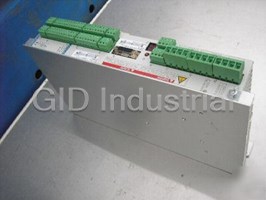
INDRAMAT DKC1.1-040-7-FW SERVO CONTROL AC ECODRIVE
Request a Quote

The quote request has been received
Close

Facing challenges or have inquiries? Feel free to contact us!
Call Us +1-469-283-2440
What they say about us
FANTASTIC RESOURCE
One of our top priorities is maintaining our business with precision, and we are constantly looking for affiliates that can help us achieve our goal. With the aid of GID Industrial, our obsolete product management has never been more efficient. They have been a great resource to our company, and have quickly become a go-to supplier on our list!
Bucher Emhart Glass
EXCELLENT SERVICE
With our strict fundamentals and high expectations, we were surprised when we came across GID Industrial and their competitive pricing. When we approached them with our issue, they were incredibly confident in being able to provide us with a seamless solution at the best price for us. GID Industrial quickly understood our needs and provided us with excellent service, as well as fully tested product to ensure what we received would be the right fit for our company.
Fuji
HARD TO FIND A BETTER PROVIDER
Our company provides services to aid in the manufacture of technological products, such as semiconductors and flat panel displays, and often searching for distributors of obsolete product we require can waste time and money. Finding GID Industrial proved to be a great asset to our company, with cost effective solutions and superior knowledge on all of their materials, it’d be hard to find a better provider of obsolete or hard to find products.
Applied Materials
CONSISTENTLY DELIVERS QUALITY SOLUTIONS
Over the years, the equipment used in our company becomes discontinued, but they’re still of great use to us and our customers. Once these products are no longer available through the manufacturer, finding a reliable, quick supplier is a necessity, and luckily for us, GID Industrial has provided the most trustworthy, quality solutions to our obsolete component needs.
Nidec Vamco
TERRIFIC RESOURCE
This company has been a terrific help to us (I work for Trican Well Service) in sourcing the Micron Ram Memory we needed for our Siemens computers. Great service! And great pricing! I know when the product is shipping and when it will arrive, all the way through the ordering process.
Trican Well Service
GO TO SOURCE
When I can't find an obsolete part, I first call GID and they'll come up with my parts every time. Great customer service and follow up as well. Scott emails me from time to time to touch base and see if we're having trouble finding something.....which is often with our 25 yr old equipment.
ConAgra Foods