

 Manufacturers
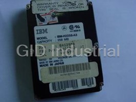
IBM IBM-H2258-A3
Description
IBM IBM-H2258-A3 258MB 2.5"/SSL IDE / AT hard drive
Part Number
IBM-H2258-A3
Price
Request Quote
Manufacturer
IBM
Lead Time
Request Quote
Category
PRODUCTS - I
Specifications
Bytes per Block
512
Idle average(3)
0.27 A RMS
Power Supply Ripple
100 mv p-p max
Read/Write
0.56 A RMS
Seek average (4)
0.40 A RMS
Standby
0.08 A RMS
Start up
0.94 A RMS (maximum peak) (5)
Supply Rise Time
7-100 ms
Tolerance (2)
+/- 5% Supply Current Pop Mean
Features
- 0.4 watts stand by
- 172/258/344 MB at (512 bytes/sector)
- 32 KB Read Buffer
- 32 KB Write Cache
- All 6 axis mounting
- ECC on the fly
- IDE interface with 6 MB/s cap transfer rate
- Magneto resistive heads
- Media data rate 20.0/32.0 Mbits/s (8 zones)
- Rotational speed 3800 rpm
- Shock 250 G (2 ms) non op
- Spin up 3 sec (typical)
Datasheet

Extracted Text
H2172-A2, H2258-A3 & H2344-A4 These 2.5" disk drives from IBM provide up to 344 MB in a slim 17 mm high package. Using the latest MR head technology IBM provides high performance drives particularly suited to the mobile computing market. APPLICATIONS High performance portable computers Non-IT--process control/fax Removable/secure storage units FEATURES 172/258/344 MB at (512 bytes/sector) IDE interface with 6 MB/s cap transfer rate Media data rate 20.0/32.0 Mbits/s (8 zones) Rotational speed 3800 rpm Magneto resistive heads 32 KB Read Buffer 32 KB Write Cache ECC on the fly 0.4 watts stand by Shock 250 G (2 ms) non op All 6 axis mounting Spin up 3 sec (typical) BENEFITS High capacity 2.5" drives Popular interface with excellent performance Excellent data rate across disk surface High areal density, low component count Fast access to data and improved throughput Low power for battery powered applications Robust design for portable computing applications ELECTRICAL CONNECTOR LOCATIONS Drive address The jumper cable is available at the interface connector to determine the drive address. Using Cable Selection, the drive address depends on the condition of pin 28 for the AT interface cable. In the case when pin 28 is ground or low, the drive is a Master. If pin 28 is open or high level, the drive is a Slave. Drive side 3 1 49 47 Jumper Position-1 48 50 (Master) 4 2 Drive side 3 1 49 47 Jumper Position 2 48 50 (Slave) 4 2 Drive side 3 1 49 47 Jumper Position-3 48 50 (Cable Selection) 4 2 Drive address by jumper cable Cabling The maximum cable length from the host system to the HDD plus circuit pattern length in the host system shall not exceed 18 inches. AT signal connection The AT signal connector is designed to mate with Dupont PN 69764-044 or equivalent. Drive Pin 43 19 3 1 49 47 Connector side view : : (20) 4 2 50 48 44 Pin AT connector Notes: 1. Pin position 20 is left blank for secure connector insertion. 2. Pin position 47 through 50 are used for drive address setting. DATA ORGANIZATION Physical layout H2172-A2 H2258-A3 H2344-A4 Bytes per Block 512 512 512 Total Customer 172 258 344 Usable Data Bytes (MB) Logical layout 989 989 915 10 15 15 34 34 49 172 258 344 DC POWER REQUIREMENTS Supply Voltage +5 Volts Power Supply Ripple 100 mv p-p max (0-20 MHz) (1) Tolerance (2) +/- 5% Supply Current Pop Mean Idle average (3) 0.27 A RMS Read/Write 0.56 A RMS Seek average (4) 0.40 A RMS Standby 0.08 A RMS Start up 0.94 A RMS (maximum peak) (5) Supply Rise Time 7-100 ms Notes: 1. The maximum supply ripple is measured at 5 volt input of the HDD. 2. The disk drive shall not incur damage for an over voltage condition of +25% (maximum duration of 20 ms) on the 5 volt nominal supply. 3. Idle average current includes communication currents. 4. The seek average current is specified based on one operation per second. 5. The worst case operating current includes motor surge. SIGNAL DEFINITION The pin assignments of interface signals are listed as follows: PIN Signal I/O PIN Signal I/O 01 -HRESET I 02 GND 03 HD07 I/O 04 HD08 I/O 05 HD06 I/O 06 HD09 I/O 07 HD05 I/O 08 HD10 I/O 09 HD04 I/O 10 HD11 I/O 11 HD03 I/O 12 HD12 I/O 13 HD02 I/O 14 HD13 I/O 15 HD01 I/O 16 HD14 I/O 17 HD00 I/O 18 HD15 I/O 19 GND (20) Key 21 (Resv) 22 GND 23 -HIOW I 24 GND 25 -HIOR I 26 GND 27 IRODY O 28 CSEL I 29 (Resv) 30 GND 31 HIRQ O 32 -HIOCS16 O 33 HA01 I 34 -PDIAG I/O 35 HA00 I 36 HA02 I 37 -HCSO I 38 -HCSI I 39 -DASP I/O 40 GND 41 +5V Logic PWR 42 +5V Motor PWR 43 GND I 44 (Resv) Note: "O" designates an output from the Drive. "I" designates an input to the Drive. "I/O" designates an input/output common. "PWP" designates a power supply to the Drive. "(Resv)" designates reserved pins which must be left unconnected. Note: There are two input pins for +5 V power supply, "+5 V LOGIC" and "+5 V MOTOR". "+5 V LOGIC" is connected to the internal logic circuits and "+5 V MOTOR" is connected to the spindle motor and motor driver. It is possible to turn on and off "+5 V LOGIC" by an external switch circuit to reduce power consumption to the least possible. In this mode, a voltage drop out due to the motor spin up current can be reduced by connecting "+5 V MOTOR" line into the system power source directly. If the above power management option is used, all signal lines that will electrically active in the host system while the HDD is disconnected from power line shall be isolated by Three-State line drivers. Internal leakage through ESD protection circuit may pull down LPUL (Least Positive Up Level) of logic signal below the specification. Use both lines in parallel, for regular HDD application. COMMAND DESCRIPTION The following Commands are supported by the Drive: COMMANDS (Hex) Check Power Mode (E5) Check Power Mode (98) Disable Lock (F6) Execute Drive Diagnostics (90) Erase Prepare (F3) Erase Unit (F4) Format Track (50) Freeze Lock (F5) Identify Drive (EC) Idle (E3) Idle (97) Idle Immediate (E1) Idle Immediate (95) Initialize Drive Parameters (91) Read Buffer (E4) Read Long (retry) (22) Read Long (no retry) (23) Read Multiple (C4) Read Sectors (retry) (20) Read Sectors (no retry) (21) Read Verify Sectors (retry) (40) Read Verify Sectors (no retry)(41) Recalibrate (1X) Seek (7X) Set Features (EF) Set Multiple (C6) Set Password (F1) Sleep (E6) Sleep (99) Standby (E2) Standby (96) Standby Immediate (E0) Standby Immediate (94) Unlock (F2) Write Buffer (E8) Write Long (retry) (32) Write Long (no retry) (33) Write Multiple (C5) Write Sectors (retry) (30) Write Sectors (no retry) (31) Write Verify (3C) OPERATING MODES Description Spin-Up Start up time period from spindle stop or power down. Seek Seek operation mode. Write Write operation mode. Read Read operation mode. Idle Spindle motor and Servo system are working normally. Other modules except the servo control and Host Interface are sleeping. Commands can be received and processed immediately. Standby Spindle motor is stopped. All modules except Interface are sleeping. Commands can be received immediately. HDD is an interrupt waiting mode with the lowest power dissipation. Notes: 1. Upon power down or Spindle stopped, a head locking mechanism will secure the heads in the ID parking position. 2. Sleep command is handled like the Standby command. Recovering from standby mode does not need soft reset nor hard reset. ELECTROMAGNETIC COMPATIBILITY The Drive meets the following EMC requirements when installed in the user system and exercised with a random accessing routine at maximum data rate: United States Federal Communication Commission (FCC) Rules and Regulation Part 15: Subject J-Computer Devices "Class B Limits." European Economic Community (EEC) directive #76/889 related to the control of radio frequency interference and the Verband Deutscher Elektrontechniker (VDE) requirements of Germany (GOP). OPERATING ENVIRONMENT Humidity: Operating Relative 8% to 90% non-condensing Non-Operating Relative 5% to 95% non-condensing Wet bulb temperature: Maximum Wet Bulb: Operating 29.4 degrees C non-condensing Non-Operating 40.0 degrees C non-condensing Elevation: Operating Altitude -50 to 3000 m Ship/Storage Altitude -150 to 30000 m Temperature: Operating 5 to 55 degrees C Storage 0 to 65 degrees C Shipping -40 to 65 degrees C Temperature Gradient 20 degrees per hour (maximum) (Operating, Storage & Shipping) Note: The system is responsible for providing sufficient air movement to maintain surface temperature below 60 degrees C at the center of top cover of the drive. AIR COOLING REQUIREMENT: The host system must provide sufficient air flow across the drive to maintain the temperature at less than 60 degrees C (measured at the center of the drives' top cover). OPERATING SHOCK The Drive will withstand (with no hard error) a 10 G half-sine wave shock pulse of 11 ms duration. NON-OPERATING SHOCK The Drive will withstand (with no permanent damage or degradation in performance) a 120 G half-sine wave shock pulse of 11 ms duration or 250 G for 2 ms. OPERATING AND NON-OPERATING VIBRATION Due to the complexity of this subject we recommend that users contact the Distributor to discuss how to perform the necessary measurements, if they believe this to be an area which requires evaluation. MECHANICAL DATA DIMENSIONS H2172-A2 H2258-A3 H2344-A4 Height (mm) 17.0 + 0.35/-0.3 17.0 + 0.35/-0.3 17.0 + 0.35/-0.3 Width (mm) 70.0 +/- 0.25 70.0 +/- 0.25 70.0 +/- 0.25 Length (mm) 100.0 +/- 0.25 100.0 +/- 0.25 100.0 +/- 0.25 Weight (gram) 173 Max 180 Max 180 Max MOUNTING ORIENTATION The drive will operate in all axes (6 directions). The drive will operate within the specified error rates when tilted +/- 5 degrees from these positions. Performance and error rate will stay within specification limits if the drive is operated in the other permissible orientations from which it was formatted Thus a drive formatted in a horizontal orientation will be able to run vertically and vice versa. The recommended mounting screw torque is 3 +/- 0.5 kgf cm. 60 146 +/- 0.6 41.6 The recommended mounting screw depth is 3.5 +/- 0.5 mm for bottom and 5.0 +/- mm for horizontal mounting. The system is responsible for mounting the drive securely enough to prevent excessive motion or vibration of the drive at seek operation or spindle rotation, using appropriate screws or equivalent mounting hardware. Consult the issuer of this specification for actual application. (6x) UNC 6-32 2 (4X) UNC 6-32 Back Front 60.3 44.4 Vibration test and shock test are to be conducted with mounting the drive to the table using bottom four screws. The maximum allowable penetration of the mounting screw is 3.5 mm. PACKAGING: The drive must be protected against Electro-Static Discharge especially when being handled. The safest way to avoid damage is to put the drive in an anti static bag before ESD wrist straps, etc are removed. 101.6 +/- 0.4 Drives should only be shipped in approved containers, severe damage can be caused to the drive if the packaging does not adequately protect against the shock levels induced when a box is dropped. Consult your IBM marketing representative if you do not have an approved shipping container. AMP is a trademark of AMP Incorporated. Molex is a trademark of Molex Incorporated. DATA MATE is a trade mark of AMP Incorporated. Western Digital is a trademark of the Western Digital Corporation. NEXT is a trademark of NEXT Corporation. This data sheet is not a substitute for the full product specification, which should be used when detailed information is required. Product Description data represents IBM's design objectives and is provided for comparative purposes; actual results may vary based on a variety of factors. This product data does not constitute a warranty. Questions regarding IBM's warranty terms or methodology used to derive this data should be referred to your IBM OEM representative. Data subject to change without notice.
Frequently asked questions
What makes Elite.Parts unique?

What kind of warranty will the IBM-H2258-A3 have?
Which carriers does Elite.Parts work with?
Will Elite.Parts sell to me even though I live outside the USA?
I have a preferred payment method. Will Elite.Parts accept it?
Why buy from GID?

Quality
We are industry veterans who take pride in our work

Protection
Avoid the dangers of risky trading in the gray market

Access
Our network of suppliers is ready and at your disposal

Savings
Maintain legacy systems to prevent costly downtime

Speed
Time is of the essence, and we are respectful of yours
Related Products


INOVA IC25N010ATDA04-0 hard drive
IBM IC25N020ATCS04-0 Hard Disk Drive - HDD IDE 2.5" 12GB - 20GB
Request a Quote

The quote request has been received
Close

Facing challenges or have inquiries? Feel free to contact us!
Call Us +1-469-283-2440
What they say about us
FANTASTIC RESOURCE
One of our top priorities is maintaining our business with precision, and we are constantly looking for affiliates that can help us achieve our goal. With the aid of GID Industrial, our obsolete product management has never been more efficient. They have been a great resource to our company, and have quickly become a go-to supplier on our list!
Bucher Emhart Glass
EXCELLENT SERVICE
With our strict fundamentals and high expectations, we were surprised when we came across GID Industrial and their competitive pricing. When we approached them with our issue, they were incredibly confident in being able to provide us with a seamless solution at the best price for us. GID Industrial quickly understood our needs and provided us with excellent service, as well as fully tested product to ensure what we received would be the right fit for our company.
Fuji
HARD TO FIND A BETTER PROVIDER
Our company provides services to aid in the manufacture of technological products, such as semiconductors and flat panel displays, and often searching for distributors of obsolete product we require can waste time and money. Finding GID Industrial proved to be a great asset to our company, with cost effective solutions and superior knowledge on all of their materials, it’d be hard to find a better provider of obsolete or hard to find products.
Applied Materials
CONSISTENTLY DELIVERS QUALITY SOLUTIONS
Over the years, the equipment used in our company becomes discontinued, but they’re still of great use to us and our customers. Once these products are no longer available through the manufacturer, finding a reliable, quick supplier is a necessity, and luckily for us, GID Industrial has provided the most trustworthy, quality solutions to our obsolete component needs.
Nidec Vamco
TERRIFIC RESOURCE
This company has been a terrific help to us (I work for Trican Well Service) in sourcing the Micron Ram Memory we needed for our Siemens computers. Great service! And great pricing! I know when the product is shipping and when it will arrive, all the way through the ordering process.
Trican Well Service
GO TO SOURCE
When I can't find an obsolete part, I first call GID and they'll come up with my parts every time. Great customer service and follow up as well. Scott emails me from time to time to touch base and see if we're having trouble finding something.....which is often with our 25 yr old equipment.
ConAgra Foods