

 Manufacturers
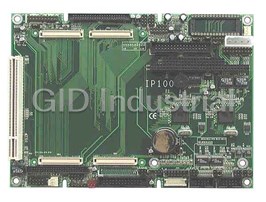
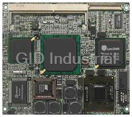
IBASE IP100L
Description
5.25" ETX Base Board with 2 LAN connectors (base board LAN & ETX CPU module LAN)...
Part Number
IP100L
Price
Request Quote
Manufacturer
IBASE
Lead Time
Request Quote
Category
SINGLE BOARD COMPUTERS
Datasheet

Extracted Text
IP100 5.25-inch form factor ETX Base Board USER ’S MANUAL Version 1.0 Acknowledgments PS/2 are trademarks of International Business Machines Corporation. Microsoft Windows is a registered trademark of Microsoft Corporation. Winbond is a registered trademark of Winbond Electronics Corporation. All other product names or trademarks are properties of their respective owners. ii IP100 User’s Manual Table of Contents Introduction ..................................................................... 1 Product Description ........................................................1 Checklist........................................................................2 Board Dimensions...........................................................3 Installations...................................................................... 4 Setting the Jumpers.........................................................5 Connectors on IP100.......................................................9 IP100 User’s Manual iii This page was intentionally left blank. iv IP100 User’s Manual INTRODUCTION Introduction Product Description The IP100 5.25-inch base board is designed for ETX CPU modules with dimensions of 100mm x 114mm. It packs all the PC connectors for the ETX CPU module to be a high-performance functional embedded board. The IP100 includes the following features: · Two Intel 82559 Ethernet controllers · Pin header for four USB ports · PS2 keyboard/mouse pin header · Pin header for VGA CRT connector · 18-bit LVDS connector (Hirose DF13) · Pin header for COM 1 and COM2 ports · Pin header for IDE and FDD connectors · Pin header for parallel port connector · DiskOnChip socket supports 2MB to 144MB flash disks · One 32-bit PCI expansion slot · One PC/104 expansion connector · 4 PCB layers · 203mm x 146mm DiskOnChip flash disks are storage devices that has no moving parts and emulates FDD/HDD with Flash/RAM/ROM offering reliable data/program storage and long life span. They are reliable and suitable for industrial or other harsh environments characterized by motion, shock, vibration, adverse temperature, dust and humidity. Other features include faster data access, longer MTBF, lower power consumption, cost effective for small capacity and small form factor. PC/104 is an ISA interface that supports compact-form-factor PC/104 modules (3.6” x 3.8”). It supports self-stacking and pin-and-socket connector. PC/104 features a standard form factor for Embedded applications. It is reliable, small in size and has low power consumption. Flexible mechanical configurations can be attained with PC/104. Modules support various functions such as display, audio, GPS, PCMCIA, fax/modem, Ethernet, SCSI, RS-232/422/485, digital I/O and SSD. IP100 User’s Manual 1 INTRODUCTION Checklist Your IP100 package should include the items listed below. Damaged or missing items should be reported to your supplier. · The IP100 Embedded Little Board · This User’s Manual · One compact disc containing the following: · Intel 82559 Ethernet Drivers · Optional cables such as: · 1 Audio Cable · 1 44-pin IDE Ribbon Cable · 1 44-pin to 40-pin IDE Ribbon Cable · 2 COM Port Cables · 1 Printer Port Cable · 1 PS/2 Keyboard/Mouse Cable · 1 VGA Cable · 1 RJ45 LAN Cable or IBLD dual RJ45 Cable 2 IP100 User’s Manual INTRODUCTION Board Dimensions IP100 User’s Manual 3 INSTALLATIONS Installations This section provides information on how to use the jumpers and connectors on the IP100 in order to set up a workable system. The topics covered are: Setting the Jumpers.........................................................5 Connectors on IP100.......................................................9 4 IP100 User’s Manual INSTALLATIONS Setting the Jumpers Jumpers are used on the IP100 to select various settings and features according to your needs and applications. Contact your supplier if you have doubts about the best configuration for your needs. The following lists the connectors on IP100 and their respective functions. Jumper Locations on IP100......................................................................6 JP2: LCD Power Setting............................................................................7 JP4: Onboard LAN2 Enable/Disable.......................................................7 JP5: Onboard LAN1 Enable/Disable.......................................................7 JP10, JP11, JP8: RS232/RS422/RS485 (COM2) Selection .....................8 JP6: DiskOnChip Address Select............................................................8 JP7: COM1/2 RS232 +5V / +12V Power Setting.....................................8 IP100 User’s Manual 5 INSTALLATIONS Jumper Locations on IP100 NOTE: Before installing the ETX CPU module, make sure of the pin orientation of both the ETX interface connectors and the ETX module connector before plugging the module. Once the module is slightly plugged in, use an even force to fully plug in the module. 6 IP100 User’s Manual INSTALLATIONS JP2: LCD Power Setting JP2 Setting Function Pin 1-2 3.3V Short/Closed Pin 2-3 5V Short/Closed JP4: Onboard LAN2 Enable/Disable JP4 Setting LAN2 Function Pin 1-2 Enabled Short/Closed Pin 2-3 Disabled Short/Closed JP5: Onboard LAN1 Enable/Disable JP5 Setting LAN1 Function Pin 1-2 Enabled Short/Closed Pin 2-3 Disabled Short/Closed IP100 User’s Manual 7 INSTALLATIONS JP10, JP11, JP8: RS232/RS422/RS485 (COM2) Selection JP10, JP11, JP8 Pin Short Function JP10: 1-2 JP11: 3-5, 4-6 RS232 JP8: 3-5, 4-6 JP10: 3-4 JP11: 1-3, 2-4 RS422 JP8: 1-3, 2-4 JP10: 5-6 JP11: 1-3, 2-4 RS485 JP8: 1-3, 2-4 JP6: DiskOnChip Address Select JP6 Setting Address Pin 1-2 D0000-D7FF Short/Closed Pin 2-3 D8000-DFFF Short/Closed JP7: COM1/2 RS232 +5V / +12V Power Setting JP7 Pin # Signal Name JP7 Signal Name JP7 Pin # 1 +5V +5V 2 3 Pin 9 (COM1) Pin 9 (COM2) 4 5 +12V +12V 6 COM1 Settings: Pin 1-3 short = +5V, Pin 3-5 short = +12V COM2 Settings: Pin 2-4 short = +5V, Pin 4-6 short = +12V 8 IP100 User’s Manual INSTALLATIONS Connectors on IP100 The connectors on IP100 allows you to connect external devices such as keyboard, floppy disk drives, hard disk drives, printers, etc. The following table lists the connectors on IP100 and their respective functions. Connector Locations on IP100..............................................................10 JP1: System Function Connector..........................................................11 P1: Main Power Connector....................................................................13 J1, J11: EIDE Connectors........................................................................13 J2, J3: USB0/USB1 Connectors .............................................................14 J4: CD-In Audio Connector...................................................................15 J5: Audio Connector...............................................................................15 J6: System Fan Power Connector..........................................................15 J7: Peripheral Power Connector.............................................................15 J8: External Floppy Drive Connector....................................................16 J9: Primary and Secondary LAN Connector........................................16 J12: External Slim Type Floppy Drive Connector...............................17 J10: PCI Slot..............................................................................................17 J13: IrDA Connector...............................................................................17 J14: TV-Out Connector (For SMI SM721 VGA)..................................17 J15: VGA CRT Connector.......................................................................18 J17: PS/2 Keyboard/Mouse Connector................................................18 J18: LCD Inverter Backlight Control.....................................................18 J19: ETX LAN RJ45 Connector.............................................................18 J20: Parallel Port Connector...................................................................19 J21, J22: COM1, COM2 Serial Ports ......................................................19 J25: 18-Bit LVDS Connector (DF13-20) ................................................20 J26: ATX Power Control Connector.....................................................20 J27: External Keyboard Connector........................................................21 CON1, CON2: PC-104 Connector..........................................................22 IP100 User’s Manual 9 INSTALLATIONS Connector Locations on IP100 10 IP100 User’s Manual INSTALLATIONS JP1: System Function Connector The System Function Connector provides interfaces for light indicators of system activities (HDD/Power) and computer status switches. Hard Disk Drive LED Reset Switch Turbo LED Connector ATX Power On Switch Green Function Power LED and Keylock Speaker Speaker: Pins 1 - 4 This connector provides an interface to a speaker for audio tone generation. An 8-ohm speaker is recommended. Pin # Signal Name 1 Speaker out 2 No connect 3 Ground 4 +5V Green Function: Pins 6 and 16 This connector is for the “Green Switch” on the control panel, which, when pressed, will force the system immediately into the power saving (sleep) mode. Pin # Signal Name 6 Sleep 16 Ground ATX Power ON Switch: Pins 7 and 17 This 2-pin connector connects to the power switch. When pressed, the power switch will force the system to power on. When pressed again, it will force the system to power off. IP100 User’s Manual 11 INSTALLATIONS Power LED and Keylock: Pins 11 - 15 The power LED indicates the status of the main power switch. The keylock switch, when closed, will disable the keyboard function. Pin # Signal Name 11 Power LED 12 No connect 13 Ground 14 Keylock 15 Ground Turbo LED Connector: Pins 8 and 18 There is the no turbo/deturbo function on the embedded board. The Turbo LED on the control panel will always be on when attached to this connector. Pin # Signal Name 8 5V 18 Ground Reset Switch: Pins 9 and 19 The reset switch allows the user to reset the system without turning the main power switch off and then on. Orientation is not required when making a connection to this header. Hard Disk Drive LED Connector: Pins 10 and 20 This connector connects to the hard drive activity LED on control panel. This LED will flash when the HDD is being accessed. 12 IP100 User’s Manual INSTALLATIONS P1: Main Power Connector The P1 main power connector has the following pin assignments. Pin # Signal Name 1 +5V 2 Ground 3 Ground 4 +12V J1, J11: EIDE Connectors J1 is the primary IDE connector. J11 is the secondary IDE connector. Signal Name Pin # Pin # Signal Name Reset IDE 1 2 Ground Host data 7 3 4 Host data 8 Host data 6 5 6 Host data 9 Host data 5 7 8 Host data 10 Host data 4 9 10 Host data 11 Host data 3 11 12 Host data 12 Host data 2 13 14 Host data 13 Host data 1 15 16 Host data 14 Host data 0 17 18 Host data 15 Ground 19 20 Key DRQ0 21 22 Ground Host IOW 23 24 Ground Host IOR 25 26 Ground IOCHRDY 27 28 Host ALE DACK0 29 30 Ground IRQ14 31 32 No connect Address 1 33 34 No connect Address 0 35 36 Address 2 Chip select 0 37 38 Chip select 1 J1: IDE1 Activity 39 40 Ground Vcc 41 42 Vcc Ground 43 44 N.C. IP100 User’s Manual 13 INSTALLATIONS Signal Name Pin # Pin # Signal Name Reset IDE 1 2 Ground Host data 7 3 4 Host data 8 Host data 6 5 6 Host data 9 Host data 5 7 8 Host data 10 Host data 4 9 10 Host data 11 Host data 3 11 12 Host data 12 Host data 2 13 14 Host data 13 Host data 1 15 16 Host data 14 Host data 0 17 18 Host data 15 Ground 19 20 Key DRQ0 21 22 Ground Host IOW 23 24 Ground Host IOR 25 26 Ground IOCHRDY 27 28 Host ALE DACK1 29 30 Ground MIRQ0 31 32 No connect Address 1 33 34 No connect Address 0 35 36 Address 2 J11: IDE2 Chip select 0 37 38 Chip select 1 Activity 39 40 Ground Vcc 41 42 Vcc Ground 43 44 N.C. J2, J3: USB0/USB1 Connectors The following table shows the pin outs of the USB pin headers connectors. Overall, the two pin headers support four USB ports. J2 Signal Name Pin Pin Signal Name 1 8 Vcc 1 8 Vcc 2 7 USB0- 2 7 USB1- 3 6 USB0+ 3 6 USB1+ 5 4 USB Ground 4 5 Ground J3 Signal Name Pin Pin Signal Name 1 8 Vcc 1 8 Vcc 2 7 USB2- 2 7 USB3- 3 6 5 USB2+ 3 6 USB3+ 4 USB Ground 4 5 Ground 14 IP100 User’s Manual INSTALLATIONS J4: CD-In Audio Connector Pin # Signal Name 1 CD Audio L 2 Ground 3 Ground 4 CD Audio R J5: Audio Connector J5, a 12-pin header connector, supports an optional external connector supporting 3 sockets for Line Out, Line In and Mic functions. The following table shows the pin assignments of this connector. Signal Name Pin # Pin # Signal Name Line Out R 1 2 Line Out L Ground 3 4 Ground Line In R 5 6 Line In L Ground 7 8 Ground Mic 9 10 BIAS Ground 11 12 NC J6: System Fan Power Connector J6 is a 3-pin header for a CPU fan. The fan must be a 12V fan. Pin # Signal Name 1 No connect 2 +12V 3 Ground J7: Peripheral Power Connector The J7 peripheral power connector has the following pin assignments. Pin # Signal Name 1 Ground 2 -5V 3 Ground 4 -12V IP100 User’s Manual 15 INSTALLATIONS J8: External Floppy Drive Connector J8 a 34-pin header for the external FDD connector. Signal Name Pin # Pin # Signal Name Ground 1 2 RM/LC Ground 3 4 No connect Ground 5 6 No connect Ground 7 8 Index Ground 9 10 Motor enable 0 Ground 11 12 Drive select 1 Ground 13 14 Drive select 0 Ground 15 16 Motor enable 1 Ground 17 18 Direction Ground 19 20 Step Ground 21 22 Write data Ground 23 24 Write gate Ground 25 26 Track 00 Ground 27 28 Write protect Ground 29 30 Read data Ground 31 32 Side 1 select Ground 33 34 Diskette change J9: Primary and Secondary LAN Connector Signal Name Pin # Pin # Signal Name LED1+ 1 11 LED1- RX+ 2 12 RX- LED2- 3 13 Ground LED2+ 4 14 Ground TX+ 5 15 TX+ LED3+ 6 16 LED3- RX+ 7 17 RX- LED4- 8 18 Ground LED4+ 9 19 Ground TX+ 10 20 TX- Note: LED1 is Link ACT LED (LAN2) LED2 is LAN2 speed LED (10M: no light, 100M: light) LED3 is Link ACT LED (LAN1) LED4 is LAN1 Speed LED (10M: no light, 100M: light) 16 IP100 User’s Manual INSTALLATIONS J12: External Slim Type Floppy Drive Connector J12 is a 26-pin connector for the slim type FDD connector. Pin Signal Signal Pin 1 VCC 2 INDEX 3 VCC 4 DRV_SEL 5 VCC 6 DSK_CH 7 NC 8 NC 9 NC 10 MOTOR 1 I DINST 12 DIR 13 NC 14 STEP 15 GND 16 WDATA 17 GND 18 EGATE 19 GND 20 TRACK 21 NC 22 WPROT 23 GND 24 RDATA 25 GND 26 SIDE J10: PCI Slot J10 of the IP100 is a 32-bit PCI slot supporting PCI cards for added functions. J13: IrDA Connector This connector is used to connector to infrared modules that supports wireless communication. Pin # Signal Name +5V IRRX IRTX 1 +5V 2 No Connect 3 Ir RX 4 Ground N.C. GND 5 Ir TX J14: TV-Out Connector (For SMI SM721 VGA) J14 is a 6-pin header that supports an S-video TV out cable. Signal Name Pin # Pin # Signal Name Comp output 1 4 Ground S-Y for S-video 2 5 Ground S-C for S-video 3 6 Ground IP100 User’s Manual 17 INSTALLATIONS J15: VGA CRT Connector J15 is a 15-pin header for an external VGA CRT female connector. Signal Name Pin Pin Signal Name Red 1 2 Vcc Green 3 4 Ground Blue 5 6 N.C. N.C. 7 8 DDDA Ground 9 10 H-Sync Ground 11 12 V-Sync Ground 13 14 DDCK Ground 15 16 N.C. J17: PS/2 Keyboard/Mouse Connector J17, a 10-pin header connector, has functions for both keyboard and mouse. The following table shows the pin assignments of this connector. Signal Name Pin # Pin # Signal Name N.C. 10 5 N.C. KB clock 9 4 Mouse clock KB data 8 3 Mouse data Vcc 7 2 Vcc Ground 6 1 Ground J18: LCD Inverter Backlight Control J18, a 2-pin header is used for the LCD inverter backlight control. J19: ETX LAN RJ45 Connector J19 is the RJ45 connector headers for the integrated LAN of the ETX CPU module. Signal Name Pin # Pin # Signal Name LED1+ 1 6 LED1- RX+ 2 7 RX- LED2- 3 8 Ground LED2+ 4 9 Ground TX+ 5 10 TX- Note: LED1 is Link ACT LED LED2 is LAN speed LED (10M: no light, 100M: light) 18 IP100 User’s Manual INSTALLATIONS J20: Parallel Port Connector The following table describes the pin out assignments of this connector. Signal Name Pin # Pin # Signal Name Line printer strobe 1 14 AutoFeed PD0, parallel data 0 2 15 Error PD1, parallel data 1 3 16 Initialize PD2, parallel data 2 4 17 Select PD3, parallel data 3 5 18 Ground PD4, parallel data 4 6 19 Ground PD5, parallel data 5 7 20 Ground PD6, parallel data 6 8 21 Ground PD7, parallel data 7 9 22 Ground ACK, acknowledge 10 23 Ground Busy 11 24 Ground Paper empty 12 25 Ground Select 13 N/A N/A J21, J22: COM1, COM2 Serial Ports J21 (COM1) and J22 (COM2) are the onboard serial ports on the IP100. Pin # Signal Name (RS-232) 1 DCD, Data carrier detect 2 RXD, Receive data 3 TXD, Transmit data 4 DTR, Data terminal ready 5 Ground 6 DSR, Data set ready 7 RTS, Request to send 8 CTS, Clear to send 9 RI, Ring indicator 10 No Connect. IP100 User’s Manual 19 INSTALLATIONS J22 (COM2) is jumper selectable for RS-232, RS-422 and RS-485. Pin # Signal Name RS-232 R2-422 RS-485 1 DCD TX- DATA- 2 RX TX+ DATA+ 3 TX RX+ NC 4 DTR RX- NC 5 Ground Ground Ground 6 DSR RTS- NC 7 RTS RTS+ NC 8 CTS CTS+ NC 9 RI CTS- NC 10 NC NC NC J25: 18-Bit LVDS Connector (DF13-20) Signal Name Pin # Pin # Signal Name TX0- 2 1 TX0+ Ground 4 3 Ground TX1- 6 5 TX1+ 5V/3.3V 8 7 Ground NC 10 9 NC TX2- 12 11 TX2+ Ground 14 13 Ground TXC- 16 15 TXC+ 5V/3.3V 18 17 ENABKL +12V 20 19 +12V J26: ATX Power Control Connector Pin # Signal Name 1 Ground 3 2 1 2 PS-ON (soft on/of) 3 5VSB (Standby +5V) 20 IP100 User’s Manual INSTALLATIONS J27: External Keyboard Connector 1 Vcc 2 KBClk (J17 pin4) 3 KBClk 4 KBDAT (J17 pin3) 5 KBDAT 6 Ground IP100 User’s Manual 21 INSTALLATIONS CON1, CON2: PC-104 Connector CON1 and CON2 are dual-in-line pin headers that support PC-104 modules. CON1 consists of 64 pins and CON2 has 40 pins. The following table shows the their pin assignments. CON1 CON2 Pin Signal Name Pin Signal Name Pin Signal Name Pin Signal Name A1 IOCHK B1 GND C1 GND D1 GND A2 D7 B2 REST C2 SBHE D2 MEMCS16 A3 D6 B3 VCC C3 LA23 D3 IOCS16 A4 D5 B4 IRQ9 C4 LA22 D4 IRQ10 A5 D4 B5 -5V C5 LA21 D5 IRQ11 A6 D3 B6 DRQ2 C6 LA20 D6 IRQ12 A7 D2 B7 -12V C7 LA19 D7 IRQ15 A8 D1 B8 OWS C8 LA18 D8 IRQ14 A9 D0 B9 +12V C9 LA17 D9 DACK0 A10 IOCHRDY B10 Key C10 MEMR D10 DRQ0 A11 AEN B11 SMEMW C11 MEMW D11 DACK5 A12 A19 B12 SMEMR C12 D8 D12 DRQ5 A13 A18 B13 IOW C13 D9 D13 DACK6 A14 A17 B14 IOR C14 D10 D14 DRQ6 ZA15 A16 B15 DACK3 C15 D11 D15 DACK7 A16 A15 B16 DRQ3 C16 D12 D16 DRQ7 A17 A14 B17 DACK1 C17 D13 D17 VCC A18 A13 B18 DRQ1 C18 D14 D18 MASTER A19 A12 B19 REFRESH C19 D15 D19 GND A20 A11 B20 CLK C20 KEY PIN D20 GND A21 A10 B21 IRQ7 A22 A9 B22 IRQ6 A23 A8 B23 IRQ5 A24 A7 B24 IRQ4 A25 A6 B25 IRQ3 A26 A5 B26 DACK2 A27 A4 B27 TC A28 A3 B28 BALE A29 A2 B29 VCC A30 A1 B30 OSC A31 A0 B31 GND A32 GND B32 GND 22 IP100 User’s Manual INSTALLATIONS IP100 User’s Manual 23
Frequently asked questions
What makes Elite.Parts unique?

What kind of warranty will the IP100L have?
Which carriers does Elite.Parts work with?
Will Elite.Parts sell to me even though I live outside the USA?
I have a preferred payment method. Will Elite.Parts accept it?


What they say about us
FANTASTIC RESOURCE
One of our top priorities is maintaining our business with precision, and we are constantly looking for affiliates that can help us achieve our goal. With the aid of GID Industrial, our obsolete product management has never been more efficient. They have been a great resource to our company, and have quickly become a go-to supplier on our list!
Bucher Emhart Glass
EXCELLENT SERVICE
With our strict fundamentals and high expectations, we were surprised when we came across GID Industrial and their competitive pricing. When we approached them with our issue, they were incredibly confident in being able to provide us with a seamless solution at the best price for us. GID Industrial quickly understood our needs and provided us with excellent service, as well as fully tested product to ensure what we received would be the right fit for our company.
Fuji
HARD TO FIND A BETTER PROVIDER
Our company provides services to aid in the manufacture of technological products, such as semiconductors and flat panel displays, and often searching for distributors of obsolete product we require can waste time and money. Finding GID Industrial proved to be a great asset to our company, with cost effective solutions and superior knowledge on all of their materials, it’d be hard to find a better provider of obsolete or hard to find products.
Applied Materials
CONSISTENTLY DELIVERS QUALITY SOLUTIONS
Over the years, the equipment used in our company becomes discontinued, but they’re still of great use to us and our customers. Once these products are no longer available through the manufacturer, finding a reliable, quick supplier is a necessity, and luckily for us, GID Industrial has provided the most trustworthy, quality solutions to our obsolete component needs.
Nidec Vamco
TERRIFIC RESOURCE
This company has been a terrific help to us (I work for Trican Well Service) in sourcing the Micron Ram Memory we needed for our Siemens computers. Great service! And great pricing! I know when the product is shipping and when it will arrive, all the way through the ordering process.
Trican Well Service
GO TO SOURCE
When I can't find an obsolete part, I first call GID and they'll come up with my parts every time. Great customer service and follow up as well. Scott emails me from time to time to touch base and see if we're having trouble finding something.....which is often with our 25 yr old equipment.
ConAgra Foods