

 Manufacturers
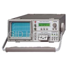
HAMEG HM1005

Description
3 channel internal 1kHz/1MHz calibrator delay time base
Part Number
HM1005
Price
Request Quote
Manufacturer
HAMEG
Lead Time
Request Quote
Category
PRODUCTS - H
Datasheet

Extracted Text
OSCILLOSCOPE The new Analog-/ Digital Scope Generation from HAMEG with Autoset, Save / Recall, Readout / Cursor and RS-232 Interface Demands Solution Modern oscilloscopes must meet additional demands without neglecting the advantages The following description explains some of their predecessors. Oscilloscopes, which are user selectable between the analog and advantages of these oscilloscopes. the digital mode, are undoubtedly the most versatile displaying instruments and meet this The excellent frequency response of requirement. In spite of additional functions, such instruments must be user friendly and the signal amplifiers and the stable trig- easy to operate. gering abilities from only 5mm peak-to- peak on the screen, enable the scope to The main demands for signal display and measurement are display sine waves far beyond its -3dB frequency without any problems. With rectangular signals the instrument‘s own � bright and sharp trace overshoot is less than 1%. � time base, single event capturing, XY and component test mode Both scopes contain a second trigger � signal amplifiers with high bandwidth and wide dynamic range system to ensure stable triggering of even � distortion free ”probe tip to screen” signal display asynchronous signal components. � high input sensitivity with minimum noise With its second time base, the � wide range of Y and X deflection coefficients HM1507-2 scope is capable of displaying � stable triggering with multiple coupling modes not only the signal itself but also a freely � delayed time base mode with second trigger system selectable expanded section in mixed mode, � automatic signal related instrument and CURSOR set up according to the time base and trigger delay � manual CURSOR supported measurement settings. This function is available in both analog and digital modes. In contrast to � 8 bit low noise flash A/D converter for each channel analog operation there is no intensity � 2048 byte displayable record length for each actual and reference signal reduction in digital mode, even if high � high data acquisition and display rates expansion ratios are chosen. � refresh, envelope, average and roll mode Low noise 8 bit flash converters are � pre and post trigger signal recording used to digitize the signals to be analyzed. � serial interface for PC supported documentation A so called dot join function linearly connects � readout parameter display successive points to display curves without � mu metal screened CRT display for highest resolution any gap. Both scopes digitize and store any � Calibrator signals for low and high frequency probe adjustment signal with more than 2000 samples per sweep. The well proven CRT is suitable to Both instruments fulfill these and more unmentioned requirements. reproduce signals in this high horizontal For additional information please see the data sheets for HM407 and HM1507-2. resolution. 6 Seitenhöhe 285 von oben Seitenhöhe 285 von oben Seitenhöhe 285 von oben Seitenhöhe 285 von oben Seitenhöhe 285 von oben Farbe S.6 Farbe S.6 Farbe S.6 Farbe S.6 Farbe S.6 OSCILLOSCOPE 100MS/s (HM407) or 200MS/s (HM may be stored and recalled randomly by 1507) allows a clear display of single shot pushing the relevant front panel key. It (real time) events up to frequencies of includes beam intensity and cursor 10MHz (HM407) or 20MHz (HM1507-2). parameters settings. To display variations of a signal over seve- The cursor functions enable the user ral samples it is recommended to use the to analyze a signal while watching the envelope or the average mode. Another numeric readout for the voltage diffe- important feature is the pre/post trigger rence, time difference, or frequency val- function that enables the user to analyze ues. The two cursors can be manually signal components that occur before/after controlled at two rates. This ensures a the trigger event. Two full-size reference high positioning accuracy. memories allow the comparison of signals with those already stored in memory. Applications Screen photo of a composite video signal. Burst When the Autoset function is enab- The screen photo shows a composite nd displayed via 2 timebase (triggered). led, all relevant parameter settings are video signal with burst. The two time performed by the scope’s circuitry auto- bases of the HM1507 are operating in the matically. The Setup parameters and the mixed mode. Since the burst is asyn- measured values are clearly displayed on chronous to other components of the TV the screen in alphanumeric characters. signal, for the correct display of the signal Autoset also initiates automatic cursor a second trigger circuit is required. This is settings for time and frequency mea- a feature of both oscilloscope types; the surement (digital only) as well as voltage HM407 uses the trigger after delay measurement. feature to display the burst whereas the In analog and digital mode, the cursor HM1507 can display the signal and the functions enable the user to analyze a nd burst (with the 2 time base) concurrently signal while watching the numeric read- in two curves. out for voltage difference, time difference, When signals are displayed in the en- or frequency values. Another feature is Screen photo of a signals in envelope mode. velope mode, the influence of jitter effects the storage capability for nine complete and amplitude changes can be demon- parameter set ups, which may be stored strated significantly. The scope builds the sec). This only applies to infrequently and recalled simply by pressing the envelope curve by storing the minimum used functions. Even inexperienced oscil- appropriate front panel key. and maximum values over a number of loscope users will soon become familiar A remarkable feature of the two scopes consecutive sampling periods. For ease with these instruments. is the built in calibrator - a 1kHz/1MHz of operation the envelope curve can be The easiest way to display signals of square wave generator. It allows fre- stored in one of the reference memories low complexity is the use of the Autoset quent checking of the instrument’s fre- and be displayed in combination with a function. The scope’s logic circuitry per- quency response - from the probe tip to currently measured signal. This eases the forms all relevant parameter settings auto- the display on the screen. It also permits evaluation when comparison is required. matically for the best readout of the signal high frequency alignment of the probes. on the screen. Of course, any parameter Supported by an On Screen Menu some Software may be modified manually if desired. The adjustments can be performed without set up parameters and the result of the The instrument functions can be con- opening the scope. selected measurement function are trolled by a PC via the built in RS232 With all of the new HAMEG scope clearly displayed on the screen. Another Interface. Disks with programming exam- range, microprocessors manage the front feature is the storage capability for nine ples, a listing of the oscilloscope com- panel inputs, calculations, and other complete parameter settings, which mands and the program SP107 for Win- control functions. In addition, 32 bit RISC dows 3.x, 95 and processors accelerate the digital signal NT4.0 are part of the processing. delivery. The SP107 The instrument may be remotely con- virtual instrument trolled by any personal computer via its program enables the built in serial interface in all relevant PC to control and functions. A suitable software program is receive instrument supplied with the scope on delivery. settings in analog and digital mode. Additio- Operation nally in digital mode, Like all members of the new series of signal data can be HAMEG oscilloscopes the two devices received for archi- combine a wide range of useful functions ving (disk), docu- with an easy to use operator interface. In mentation (printer) spite of the numerous functions the front and exportation (ta- panel is clearly designed. The logically ble calculation) purpo- designed layout and the proven func- ses. The data transfer tionality of the keys and knobs make can be started ma- additional menu keys avoidable. To reduce nually, or automatical- the number of front panel keys, some ly (time interval / single allow a second function that can be acti- event) controlled. vated by pressing and holding (approx. 2 7 Seitenhöhe 285 von oben Seitenhöhe 285 von oben Seitenhöhe 285 von oben Seitenhöhe 285 von oben Seitenhöhe 285 von oben Farbe S.7 Farbe S.7 Farbe S.7 Farbe S.7 Farbe S.7 OSCILLOSCOPE The 40 MHz (100MS/s) Analog-/Digital-Oscilloscope HM407 Autoset Auto Cursor Readout / Cursor Save / Recall Reference Memories Delay Time Base Component Tester 1kHz/1MHz Calibrator RS232 Interface Analog: Digital: � � � � � 2 x DC-40MHz, 2 x 1mV-50V/div � � � � � Refresh, Single, Roll-, Envelope-, Average-,XY-Mode � � � � � Time Base 0.5s/div. to 10ns/div. � � � � � Max.Sampling Rate 100MS/s, Storage 2x2048x8 bit nd � � � � � Time Base with Delay and 2 Trigger � � � � � Time Base 100s/div - 0.1μs/div, 2 Reference Memories � � � � � Triggering DC-100MHz, TV Sync. Sep. � � � � � Pre Trigger 25-50-75-100%, Post Trigger 25-50-75% � � � � � 1kHz/1MHz Calibrator, CRT with 2kV � � � � � Screen Refresh 180/s, Dot Join (linear) Specifications Readout & Cursor (analog/digital) Horizontal Deflection Vertical Deflection Display of parameter settings and other functions Analog: on the screen. Triggerpoint indication. Cursor Time coefficients: 22 calibrated steps Operating modes: Channel I or II separate, measurement of ΔU, Δt or 1/Δt (frequency), sepa- 0.5s – 50ns/div. (±3%) in 1-2-5 sequence both channels•alternated or chopped rate or in tracking mode. variable 2.5:1 up to 1.25s/div.(uncal.) Chopper frequency: approx. 0.5MHz Readout intensity: separately adjustable X-MAG.x10: up to 10ns/div. ±5% Sum or Difference: from CH I and CH II Delay: approx. 140ms – 200ns, variable Invert: CH II Interface Hold-off time: variable to approx. 10:1 XY-Mode: via channel I (X) and channel II(Y) PC remote control: built in RS232 interface Input X-amplifier: CH II, sensitiv. see CH II Frequency range: 2 x DC – – – – – 40MHz (-3dB) Option: HO79-6 Multifunction-Interface Bandwidth X-Amplifier: 0 – 3MHz (-3dB) Overshoot: ≤1% IEEE-Bus, RS232, and Centronics XY-phase shift: <3° below 120kHz. Risetime: <8.75ns. Output formats (HO79-6): PCL, Post Script Digital: Overshoot: ≤1% HPGL, EPSON Time Base: 100s–1μs/div (±3%) in 1-2-5 sequ. Deflection coefficient: 14 calibrated positions Component Tester X-MAG. x10 (±5%): 100ns/div. from 1mV/div to 20V/div in 1-2-5 sequence, Bandwidth X-Amplifier: 0–20MHz (-3dB) variable 2.5:1 to min. 50V/div. Test voltage: max. 7V (o/c). rms XY-phase shift: <3° below 20MHz. Accuracy in calibrated positions Test current: max. 7mA (s/c) rms 1mV/div – 2mV/div: ±5%(DC-10MHz(-3dB)) Test frequency: approx.50Hz. Digital Storage 5mV/div – 20V/div: ±3% One test lead is grounded (Safety Earth) Operating modes: Refresh, Roll, Single, XY Input impedance: 1MΩ II 18pF General Information Average, (2 to 512 waveforms), Envelope Input coupling: DC - AC - GD (ground) Dot Join function: automatically CRT: D14-363GY, 8x10cm internal graticule Input voltage: max. 400V (DC + peak AC) Acquisition (real time): Acceleration voltage: approx 2kV Triggering 8 bit flash A/D: max. 100MS/s Trace rotation: adjustable on front panel Display refresh rate: max. 180/s Z Input: (Intens. modulation), max. +5V (TTL) Automatic (peak to peak): ≥0.5div. Calibrator: 0,2V ±1%, ≈ 1kHz/1MHz (t <4ns) Memory & display: 2k x 8bit per channel. r Range: up 20Hz-100MHz Reference memory: 2 waveforms 2k x 8bit Line voltage: 100-240V AC ±10%, 50/60Hz Normal with level control: DC-100MHz ( Saved in: EEPROM Power consumption: approx. 42Watt / 50Hz ≥0.5div.) Min./Max. ambient temperature: 0°C...+40°C Resolution (samples/div.): X 200/div. Indicator for trigger action: LED Protective system: Safety class I (IEC1010-1) Y 25 /div. Slope: positive or negative Weight: approx. 5.6kg, Color: techno-brown XY 25 x 25/div. Sources: CH I or II, line, external Cabinet: W 285, H 125, D 380 mm Pre-/Post Trigger: 25,50,75,100, -25,-50,-75% ALT. Triggering: CHI / CHII (≥ 0.8div.) Lockable tilt handle Coupling: AC (10Hz –100MHz) Operation / Control Subject to change without notice. 04/99 DC (0 –100MHz) Manual: front panel switches HF (50kHz – 100MHz) Auto Set: signal related automatic LF (0 – 1.5kHz) nd parameter selection 2 triggering: normal with level control Accessories supplied: Save& Recall: 9user definedparametersettings External: ≥0.3V (0 – 100MHz) pp Operators Manual, 4 Disks, + Active TV Sync. Separator: field & line, / – Line Cord, 2 Probes 1:1/10:1 8 Seitenhöhe 285 von oben Seitenhöhe 285 von oben Seitenhöhe 285 von oben Seitenhöhe 285 von oben Seitenhöhe 285 von oben Farbe S.8 Farbe S.8 Farbe S.8 Farbe S.8 Farbe S.8
Frequently asked questions
What makes Elite.Parts unique?

What kind of warranty will the HM1005 have?
Which carriers does Elite.Parts work with?
Will Elite.Parts sell to me even though I live outside the USA?
I have a preferred payment method. Will Elite.Parts accept it?


What they say about us
FANTASTIC RESOURCE
One of our top priorities is maintaining our business with precision, and we are constantly looking for affiliates that can help us achieve our goal. With the aid of GID Industrial, our obsolete product management has never been more efficient. They have been a great resource to our company, and have quickly become a go-to supplier on our list!
Bucher Emhart Glass
EXCELLENT SERVICE
With our strict fundamentals and high expectations, we were surprised when we came across GID Industrial and their competitive pricing. When we approached them with our issue, they were incredibly confident in being able to provide us with a seamless solution at the best price for us. GID Industrial quickly understood our needs and provided us with excellent service, as well as fully tested product to ensure what we received would be the right fit for our company.
Fuji
HARD TO FIND A BETTER PROVIDER
Our company provides services to aid in the manufacture of technological products, such as semiconductors and flat panel displays, and often searching for distributors of obsolete product we require can waste time and money. Finding GID Industrial proved to be a great asset to our company, with cost effective solutions and superior knowledge on all of their materials, it’d be hard to find a better provider of obsolete or hard to find products.
Applied Materials
CONSISTENTLY DELIVERS QUALITY SOLUTIONS
Over the years, the equipment used in our company becomes discontinued, but they’re still of great use to us and our customers. Once these products are no longer available through the manufacturer, finding a reliable, quick supplier is a necessity, and luckily for us, GID Industrial has provided the most trustworthy, quality solutions to our obsolete component needs.
Nidec Vamco
TERRIFIC RESOURCE
This company has been a terrific help to us (I work for Trican Well Service) in sourcing the Micron Ram Memory we needed for our Siemens computers. Great service! And great pricing! I know when the product is shipping and when it will arrive, all the way through the ordering process.
Trican Well Service
GO TO SOURCE
When I can't find an obsolete part, I first call GID and they'll come up with my parts every time. Great customer service and follow up as well. Scott emails me from time to time to touch base and see if we're having trouble finding something.....which is often with our 25 yr old equipment.
ConAgra Foods