GEI-100364C
Supersedes GEI-100364B
GE Fuji Drives USA
™
AF-300 P11
User’s Guide
© 1999, 2000 by GE Fuji Drives USA, Inc.
All rights reserved.
These instructions do not purport to cover all details or variations in equipment, nor to provide every possible
contingency to be met during installation, operation, and maintenance. If further information is desired, or if particular
problems arise that are not covered sufficiently for the purchaser’s purpose, the matter should be referred to GE Fuji
Drives USA, Salem, Virginia, USA.
This document contains proprietary information of GE Fuji Drives USA and is furnished to its customer solely to
assist that customer in the installation, testing, operation, and/or maintenance of the equipment described. This
document shall not be reproduced in whole or in part, nor shall its contents be disclosed to any third party without
the written approval of GE Fuji Drives USA.
AF-300 P11 is a trademark of GE Fuji Drives USA, Inc.
Energy $aver is a registered trademark of General Electric Company, USA.
Genius is a registered trademark of GE Fanuc Automation North America, Inc.
Profibus is a trademark of Profibus International.
X$D is a trademark of General Electric Company, USA.
WARNING:
This equipment contains a potential hazard of electric shock or burn. Only personnel who are adequately trained
and thoroughly familiar with the equipment and the instructions should install, operate, or maintain this equipment.
Isolation of test equipment from the equipment under test presents potential electrical hazards. If the test equipment
cannot be grounded to the equipment under test, the test equipment’s case must be shielded to prevent contact by
personnel.
To minimize hazard of electrical shock or burn, approved grounding practices and procedures must be strictly
followed.
WARNING:
To prevent personal injury or equipment damage caused by equipment malfunction, only adequately trained person-
nel should modify any programmable machine.
Table of Contents
i. Preface .................................................................... i
Safety Instructions .................................................. iii
Setting Function Data ..................................... 4-5
Model Numbering System Diagram....................... vii
Checking Function Data ................................. 4-7
Dimensions & Weights .......................................... viii
Monitoring Operating Status .......................... 4-7
I/O Check ........................................................ 4-8
1. Before Using This Product 1-1 Maintenance Information ................................ 4-9
Receiving Instructions.......................................... 1-1 Load Rate Measurement .............................. 4-10
Alarm Information ......................................... 4-11
Appearance.......................................................... 1-1
Handling the Product ........................................... 1-2 Alarm History and Factors ............................ 4-12
Carrying ............................................................... 1-3 Data Copy ..................................................... 4-13
Alarm Mode .................................................. 4-15
Storage ................................................................ 1-3
Ratings Efficiency and Watts Loss ...................... 1-4
5. Function Selection 5-1
2. Installation Environment and Connection 2-1 Function Selection List ........................................ 5-1
Alphabetical Function List ................................... 5-5
Operating Environment ........................................ 2-1
Installation Method .............................................. 2-1 Function Explanation ........................................... 5-7
Connection........................................................... 2-3 F: Fundamental Functions .............................. 5-7
E: Extensions Terminal Functions ................. 5-18
Basic Connection Diagrams ........................... 2-4
Connecting the Main Circuit and C: Control Functions of Frequency............... 5-28
Ground Terminals ....................................... 2-8
Connecting the Control Terminals ................ 2-11
6. Protective Operations 6-1
Terminal Configuration .................................. 2-15
List of Protective Functions ................................. 6-1
Cable Size, Tightening Torque &
Alarm Reset ......................................................... 6-2
Circuit Protection Rating .......................... 2-16
DC Link Reactor ........................................... 2-17
7. Troubleshooting 7-1
Activation of Protective Function ......................... 7-1
3. Operation 3-1
Abnormal Motor Rotation .................................... 7-5
Inspection and Preparation Before Operation ..... 3-1
Operation Method ................................................ 3-1
8. Maintenance and Inspection 8-1
Trial Run ............................................................... 3-1
Daily Inspections .................................................. 8-1
Periodic Inspections ............................................ 8-1
4. Keypad Panel 4-1
Main Circuit Measurements ................................. 8-4
Appearance of Keypad Panel .............................. 4-1
Insulation Test ...................................................... 8-5
Operation From the Keypad Panel ...................... 4-2
Replacement Parts .............................................. 8-5
Normal Operation ........................................... 4-2
Alarm Modes .................................................. 4-2
9. Warranty Parts and Service 9-1
Entering Data on the Keypad Panel .................... 4-4
In-Warranty Failure Checklist ............................... 9-2
Operation Mode.............................................. 4-4
Setting Digital Frequency ............................... 4-4
Switching to LED Digital Monitor .................... 4-5
Program Menu Screen .................................... 4-5
i
10. Replacement Parts 10-1
11. Specifications 11-1
Standard Specifications ..................................... 11-1
Common Specifications..................................... 11-3
Outline Dimensions ............................................ 11-5
Keypad Mounting Hole .................................... 11-12
12. RS485 Modbus RTU Serial Communications 12-1
Transmission Specification ................................ 12-1
Connection......................................................... 12-1
Serial Interface Configuration ............................ 12-1
Modbus RTU Functions ..................................... 12-1
Drive Function Code Access ............................. 12-2
Command and Monitor Data Registers ............. 12-2
Data Format Specification ................................. 12-4
Communication Errors ....................................... 12-8
13. Options 13-1
Built-in Options .................................................. 13-1
14. Electromagnetic Compatibility (EMC) 14-1
General............................................................... 14-1
Recommended Installation Instructions ............ 14-1
ii
Safety Instructions
Read this manual carefully before installing, connecting (wiring), operating, servicing, or inspecting the drive.
Familiarize yourself with all safety features before using the drive.
In this manual, safety messages are classified as follows:
WARNING Improper operation may result in serious personal injury or death.
CAUTION Improper operation may result in slight to medium personal injury or property damage.
Situations more serious than those covered by CAUTION will depend on prevailing circumstances.
Always follow instructions.
Instructions on Use
WARNING
• This drive is designed to drive a 3-phase induction motor and is not suitable for a single-phase or
other types of motors.
• This drive may not be used as a component of a life-support system or other medical device directly
affecting the personal welfare of the user.
• This drive is manufactured under strict quality control standards. However, safety equipment must be
installed or the failure of this device may result in personal injury, property damage, or risk an accident.
Instructions on Installation
WARNING
• Mount this drive on an incombustible material such as metal, otherwise a risk of fire may result.
• Do not place combustible or flammable material near this drive, as fire may result.
CAUTION
• Do not hold or carry this drive by its cover. Do not drop the converter, as injury may result.
• Ensure that the drive and heat sink surfaces are kept free of foreign matter (lint, paper dust, small chips of
wood or metal, and dust), as fire or accident may result.
• Do not install or operate a damaged drive or a drive with missing parts, as electric shock or
injury may occur.
iii
Instructions on Wiring
WARNING
• Connect the drive to power via a line-protection molded-case circuit breaker or fuse, as fire may result.
Always connect a ground wire, as electric shock or fire may result.
• A licensed specialist must perform all wiring work, as electric shock may result.
• Turn off the power before wiring, as electric shock may result.
• Wire the drive after mechanical installation is complete, as electric shock or injury may occur.
CAUTION
• Confirm that the number of phases and rated voltage of this product match those of the AC power supply,
otherwise injury may result.
• Do not connect the AC power supply to the output terminals (U, V, and W), as injury may result.
• Do not directly connect a braking resistor to the DC terminals (P(+) and N(-)), as fire may result.
• Ensure that the noise generated by the drive, motor, or wiring does not adversely affect peripheral
sensors and equipment, as an accident may result.
Instructions on Operation
WARNING
• Be sure to install the cover before turning on the power. Do not remove the cover while power to the drive
is turned on. Electric shock may occur.
• Do not operate switches with wet hands, as electric shock may result. When the retry function is selected,
the drive may restart automatically after tripping. Design the machine to ensure personal safety in the
event of restart. Accident may result.
• When the torque limiting function is selected, operating conditions may differ from preset parameters
(acceleration/deceleration time or speed). In this case, personal safety must be assured.
An accident may result.
• The STOP key is only effective when a function setting has been established. Install an independent
emergency switch to disable the STOP key on the keypad panel when an operation is selected via the
external signal terminal, otherwise an accident may result.
• Operations can start up suddenly, after an alarm is reset, if there is a run signal present.
Confirm that the run signal input is not present before resetting the alarm. Accident may result.
• Do not touch drive terminals when energized, even if the drive has stopped. Electric shock may result.
CAUTION
• Do not start or stop the drive using the main circuit power. Failure may result.
• Do not touch the heat sink or braking resistor because they become very hot. Burns may result.
• Since the drive can reach high speed operation easily, carefully check the performance of motor or
machine before changing any speed settings. Injury may result.
• Do not use the drive braking function for mechanical holding. Injury may result.
iv
Instructions on Maintenance, Inspection, and Replacement
WARNING
• Wait a minimum of five minutes (30HP or less) or ten minutes (40HP or more) after power has been turned
off (open) before starting inspection. Also confirm that the charge lamp is off and that DC voltage between
terminals P(+) and N(-) does not exceed 25V. Electrical shock may result.
• Only authorized personnel should perform maintenance, inspection, and replacement operations.
Remove all metal jewelry such as watches and rings. Use insulated tools only. Electric shock or injury
may result.
Instructions on Disposal
CAUTION
• Treat as industrial waste when disposing of drive. Injury may result.
Instructions for UL/cUL Requirements
CAUTION
• Hazard of electrical shock. Disconnect incoming power before working on this control.
• Dangerous voltage exist until charge light is off.
• Type1 - indoor use only.
• Tightening torque and wire size for field wiring terminal are marked adjacent to the terminal or on
the wiring diagram.
• The drive shall be connected with Listed Class J Fuse or Circuit Breaker rated 600V as shown in the
Table 2-3-5 (30 HP or less).
• In case of using auxiliary control-power input, connect it by referring to the basic connection
diagram (2-3-1).
• Suitable for use on a circuit capable of delivering not more than 5000rms symmetrical amperes,
for 230V (230V series), 480V (460V series) maximum up to 30HP; 42000rms symmetrical amperes
230V (230V series), 480V (460V series) maximum 40HP and above.
• Use 60/75 °C CU wire only.
• A Class 2 circuit wired with Class 1 wire (30HP or less). Use Class 1 wire only (40HP or more).
• Field wiring connection must be made by a UL Listed and CSA Certified closed-loop terminal connector
sized for the wire gauge involved. Connector must be fixed using the crimp tool specified by the connector
manufacturer.
• Solid state motor overload protection is provided in each model.
Other Instructions
WARNING
• Never modify the product. Electric shock or injury may result.
v
Conformity to Low Voltage Directive in Europe
CAUTION
• The contact capacity of alarm output for any fault (30A, B, C) and relay signal output (Y5A, Y5C) is
0.5A at 48V DC, 0.3A ≤ 250 VAC
• The ground terminal (G) should be connected to ground. Use a crimp terminal to connect a cable to
the main circuit terminal or drive ground terminal.
• Where a residual-current protective device (RCD) is used for protection in case of direct or indirect
contact, only a type B device is allowed on the supply side of this electrical equipment. Otherwise,
another protective measure shall be applied such as separation of the electrical equipment from the
environment by double or reinforced insulation or isolation of the electrical equipment and supply
system by the transformer.
• Use a single cable to connect the (G) drive ground terminal. Do not use two or more drive ground
terminals.
• Use only a molded-case circuit breaker (MCCB) or magnetic contactor (MC) that conform to EN or IEC
standards.
• Operate the drive under over-voltage Category III conditions and maintain Pollution Degree 2 or
better as specified in IEC664. To maintain Pollution Degree 2 or better, install the drive in a control
panel structure (level NEMA 3 or higher) which is free from water, oil, carbon, dust, etc.
• For the input-output wiring of the drive, use cable diameter and type as specified in Appendix C
in EN60204.
• To ensure safety, install an optional AC reactor, DC reactor, or external braking resistor as follows:
1) Install inside an IP4X cabinet or barrier if electrical parts are exposed.
2) Install inside an IP2X cabinet or barrier if electrical parts are not exposed.
• In case of external cooling system, cover the drive rear side in order not to touch the main capacitor
and braking resistor.
General Instructions
For clarity, some figures in this manual may show the drive with covers and safety screens removed for
explanation purposes. Do not operate the device until all such covers and screens have been replaced.
vi
™
AF-300 P11 Model Numbering System Diagram
Description 6K P11 N N (X/N)NN X N X N
GE Product Code
AF-300 Drive Family
Input Voltage
2 = 230V 50/60 Hz
4 = 460V 50/60 Hz
Input Phases
3 = 3 Phase
Horsepower
F50 = 1/2 Hp
010 = 10 Hp
100 = 100 Hp
Factory Installed Options
N = None
X = Keypad
B = to be determined
Enclosure Type
1 = NEMA 1 (UL Type 1)
2 = NEMA 12 (UL Type 12)
4 = NEMA 4 (UL Type 4)
8 = IP00 with NEMA 12 heatsink
9 = IP00
Product Revision
A = 1st Revision
B = 2nd Revision
Minor Product Revision
1 = 1st Minor Revision
2 = 2nd Minor Revision
vii
AF-300 P11 Dimensions & Weights
AF-300 P11
HP NEMA Rated Output Overload AF-300P11 Catalog Dimensions Weight
Rating Enclosure Current (A) (110% 1min.) Model No. No. H x W x D (inches) (lbs)
230VAC, 3 phase, 50/60Hz Input, NEMA 1
0.25 1 1.5 1.7 6KP1123F25X1## D6600 10.24 x 4.33 x 5.12 4.8
0.5 1 3 3.3 6KP1123F50X1## D6601 10.24 x 4.33 x 5.12 4.8
1 1 5 5.5 6KP1123001X1## D6602 10.24 x 4.33 x 5.71 5.5
2 1 8 8.8 6KP1123002X1## D6603 10.24 x 5.91 x 5.71 8.4
3 1 11 12 6KP1123003X1## D6604 10.24 x 5.91 x 5.71 8.4
5 1 17 19 6KP1123005X1## D6605 10.24 x 5.91 x 5.71 8.4
7.5 1 22 24 6KP1123007X1## D6606 10.24 x 8.66 x 7.68 12.6
10 1 29 32 6KP1123010X1## D6607 10.24 x 8.66 x 7.68 12.6
15 1 42 46 6KP1123015X1## D6608 10.24 x 8.66 x 7.68 12.6
20 1 55 61 6KP1123020X1## D6609 15.75 x 9.84 x 7.68 22.0
25 1 67 74 6KP1123025X1## D6610 15.75 x 9.84 x 7.68 22.0
30 1 78 86 6KP1123030X1## D6611 15.75 x 9.84 x 7.68 23.1
40 1 115 127 6KP1123040X1## D6612 29.7 x 13.5 x 10.0 70
50 1 145 160 6KP1123050X1## D6613 29.7 x 13.5 x 10.0 70
60 1 180 198 6KP1123060X1## D6614 33.1 x 14.9 x 10.6 86
75 1 215 237 6KP1123075X1## D6615 38.0 x 14.9 x 10.6 106
100 1 283 311 6KP1123100X1## D6616 38.0 x 14.9 x 10.6 110
125 1 346 381 6KP1123125X1## D6617 41.3 x 21.0 x 11.2 172
150 1 415 457 6KP1123150X1## D6618 50.4 x 26.9 x 14.2 282
230VAC, 3 phase, 50/60Hz Input, NEMA 4
0.25 4 1.5 1.7 6KP1123F25X4## D6650 10.24 x 4.33 x 5.12 4.8
0.5 4 3 3.3 6KP1123F50X4## D6651 10.24 x 4.33 x 5.12 4.8
1 4 5 5.5 6KP1123001X4## D6652 10.24 x 4.33 x 5.71 5.5
2 4 8 8.8 6KP1123002X4## D6653 10.24 x 5.91 x 5.71 8.4
3 4 11 12 6KP1123003X4## D6654 10.24 x 5.91 x 5.71 8.4
5 4 17 19 6KP1123005X4## D6655 10.24 x 5.91 x 5.71 8.4
7.5 4 22 24 6KP1123007X4## D6656 10.24 x 8.66 x 7.68 12.6
10 4 29 32 6KP1123010X4## D6657 10.24 x 8.66 x 7.68 12.6
15 4 42 46 6KP1123015X4## D6658 10.24 x 8.66 x 7.68 12.6
230VAC, 3 phase, 50/60Hz Input, NEMA 12
20 12 55 61 6KP1123020X2## D6659 15.75 x 9.84 x 7.68 22.0
25 12 67 74 6KP1123025X2## D6660 15.75 x 9.84 x 7.68 22.0
30 12 78 86 6KP1123030X2## D6661 15.75 x 9.84 x 7.68 23.1
230VAC, 3 phase, 50/60Hz Input, Open
40 Open 115 127 6KP1123040X9## --- 21.7 x 13.4 x 10.0 64
50 Open 145 160 6KP1123050X9## --- 21.7 x 13.4 x 10.0 64
60 Open 180 198 6KP1123060X9## --- 24.2 x 14.8 x 10.6 79
75 Open 215 237 6KP1123075X9## --- 29.1 x 14.8 x 10.6 97
100 Open 283 311 6KP1123100X9## --- 29.1 x 14.8 x 10.6 101
125 Open 346 381 6KP1123125X9## --- 29.5 x 20.9 x 11.2 154
150 Open 415 457 6KP1123150X9## --- 34.6 x 26.8 x 14.2 253
## Indicates product revision.
Note: Hp rating is shown for 230V and 460V nominal systems.
When applying at lower voltage, select the drive by rated current and not Hp rating.
viii
AF-300 P11 Dimensions & Weights
AF-300 P11
HP NEMA Rated Output Overload AF-300P11 Catalog Dimensions Weight
Rating Enclosure Current (A) (110% 1min.) Model No. No. H x W x D (inches) (lbs)
230VAC, 3 phase, 50/60Hz Input, Open with NEMA 12 Heatsink
40 Open 115 127 6KP1123040X8## --- 21.7 x 13.4 x 10.0 64
50 Open 145 160 6KP1123050X8## --- 21.7 x 13.4 x 10.0 64
60 Open 180 198 6KP1123060X8## --- 24.2 x 14.8 x 10.6 79
75 Open 215 237 6KP1123075X8## --- 29.1 x 14.8 x 10.6 97
100 Open 283 311 6KP1123100X8## --- 29.1 x 14.8 x 10.6 101
125 Open 346 381 6KP1123125X8## --- 29.5 x 20.9 x 11.2 154
150 Open 415 457 6KP1123150X8## --- 34.6 x 26.8 x 14.2 253
460VAC, 3 phase, 50/60Hz Input, NEMA 1
0.5 1 1.5 1.7 6KP1143F50X1## D6649 10.24 x 4.33 x 5.12 4.8
1 1 2.5 2.8 6KP1143001X1## D6619 10.24 x 4.33 x 5.71 5.5
2 1 3.7 4.1 6KP1143002X1## D6620 10.24 x 5.91 x 5.71 8.4
3 1 5.5 6.1 6KP1143003X1## D6621 10.24 x 5.91 x 5.71 8.4
5 1 9 9.9 6KP1143005X1## D6622 10.24 x 5.91 x 5.71 8.4
7.5 1 12.5 14 6KP1143007X1## D6623 10.24 x 8.66 x 7.68 13.4
10 1 16.5 18 6KP1143010X1## D6624 10.24 x 8.66 x 7.68 13.4
15 1 23 25 6KP1143015X1## D6625 10.24 x 8.66 x 7.68 13.4
20 1 30 33 6KP1143020X1## D6626 15.75 x 9.84 x 7.68 22.0
25 1 37 41 6KP1143025X1## D6627 15.75 x 9.84 x 7.68 22.0
30 1 44 48 6KP1143030X1## D6628 15.75 x 9.84 x 7.68 23.1
40 1 60 66 6KP1143040X1## D6630 29.7 x 13.5 x 10.0 70
50 1 75 83 6KP1143050X1## D6631 29.7 x 13.5 x 10.0 70
60 1 91 100 6KP1143060X1## D6632 29.7 x 14.9 x 10.6 82
75 1 112 123 6KP1143075X1## D6633 34.6 x 14.9 x 10.6 95
100 1 150 165 6KP1143100X1## D6634 34.6 x 14.9 x 10.6 97
125 1 176 194 6KP1143125X1## D6635 38.0 x 14.9 x 10.6 115
150 1 210 231 6KP1143150X1## D6636 38.0 x 21.0 x 12.4 174
200 1 253 278 6KP1143200X1## D6637 38.0 x 21.0 x 12.4 174
250 1 304 334 6KP1143250X1## D6638 53.1 x 21.0 x 14.2 245
300 1 377 415 6KP1143300X1## D6639 53.1 x 21.0 x 14.2 245
350 1 415 457 6KP1143350X1## D6640 55.1 x 26.9 x 14.2 337
400 1 485 534 6KP1143400X1## D6641 55.1 x 26.9 x 14.2 337
450 1 520 572 6KP1143450X1## D6642 55.1 x 26.9 x 14.2 337
500 1 650 715 6KP1143500X1## D6643 57.1 x 26.8 x 17.7 562
600 1 740 814 6KP1143600X1## D6644 57.1 x 26.8 x 17.7 562
700 1 840 924 6KP1143700X1## D6645 57.1 x 34.6 x 17.7 804
800 1 960 1056 6KP1143800X1## D6646 57.1 x 34.6 x 17.7 804
460VAC, 3 phase, 50/60Hz Input, NEMA 4
0.5 4 1.5 1.7 6KP1143F50X4## D6699 10.24 x 4.33 x 5.12 4.8
1 4 2.5 2.8 6KP1143001X4## D6669 10.24 x 4.33 x 5.71 5.5
2 4 3.7 4.1 6KP1143002X4## D6670 10.24 x 5.91 x 5.71 8.4
3 4 5.5 6.1 6KP1143003X4## D6671 10.24 x 5.91 x 5.71 8.4
5 4 9 9.9 6KP1143005X4## D6672 10.24 x 5.91 x 5.71 8.4
7.5 4 12.5 14 6KP1143007X4## D6673 10.24 x 8.66 x 7.68 13.4
10 4 16.5 18 6KP1143010X4## D6674 10.24 x 8.66 x 7.68 13.4
15 4 23 25 6KP1143015X4## D6675 10.24 x 8.66 x 7.68 13.4
## Indicates product revision.
Note: Hp rating is shown for 230V and 460V nominal systems.
When applying at lower voltage, select the drive by rated current and not Hp rating.
ix
AF-300 P11 Dimensions & Weights
AF-300 P11
HP NEMA Rated Output Overload AF-300P11 Catalog Dimensions Weight
Rating Enclosure Current (A) (110% 1min.) Model No. No. H x W x D (inches) (lbs)
460VAC, 3 phase, 50/60Hz Input, NEMA 12
20 12 30 33 6KP1143020X2## D6676 15.75 x 9.84 x 7.68 22.0
25 12 37 41 6KP1143025X2## D6677 15.75 x 9.84 x 7.68 22.0
30 12 44 48 6KP1143030X2## D6678 15.75 x 9.84 x 7.68 23.1
460VAC, 3 phase, 50/60Hz Input, Open
40 Open 60 66 6KP1143040X9## --- 21.7 x 13.4 x 10.0 64
50 Open 75 83 6KP1143050X9## --- 21.7 x 13.4 x 10.0 64
60 Open 91 100 6KP1143060X9## --- 21.7 x 14.8 x 10.6 75
75 Open 112 123 6KP1143075X9## --- 26.6 x 14.8 x 10.6 86
100 Open 150 165 6KP1143100X9## --- 26.6 x 14.8 x 10.6 88
125 Open 176 194 6KP1143125X9## --- 29.1 x 14.8 x 10.6 106
150 Open 210 231 6KP1143150X9## --- 29.1 x 20.9 x 12.4 154
200 Open 253 278 6KP1143200X9## --- 29.1 x 20.9 x 12.4 154
250 Open 304 334 6KP1143250X9## --- 39.4 x 20.9 x 14.2 220
300 Open 377 415 6KP1143300X9## --- 39.4 x 20.9 x 14.2 220
350 Open 415 457 6KP1143350X9## --- 39.4 x 26.8 x 14.2 308
400 Open 485 534 6KP1143400X9## --- 39.4 x 26.8 x 14.2 308
450 Open 520 572 6KP1143450X9## --- 39.4 x 26.8 x 14.2 308
500 Open 650 715 6KP1143500X9## --- 55.1 x 26.8 x 17.7 551
600 Open 740 814 6KP1143600X9## --- 55.1 x 26.8 x 17.7 551
700 Open 840 924 6KP1143700X9## --- 55.1 x 35.6 x 17.7 793
800 Open 960 1056 6KP1143800X9## --- 55.1 x 35.6 x 17.7 793
460VAC, 3 phase, 50/60Hz Input, Open with NEMA 12 Heatsink
40 Open 60 66 6KP1143040X8## --- 21.7 x 13.4 x 10.0 64
50 Open 75 83 6KP1143050X8## --- 21.7 x 13.4 x 10.0 64
60 Open 91 100 6KP1143060X8## --- 21.7 x 14.8 x 10.6 75
75 Open 112 123 6KP1143075X8## --- 26.6 x 14.8 x 10.6 86
100 Open 150 165 6KP1143100X8## --- 26.6 x 14.8 x 10.6 88
125 Open 176 194 6KP1143125X8## --- 29.1 x 14.8 x 10.6 106
150 Open 210 231 6KP1143150X8## --- 29.1 x 20.9 x 12.4 154
200 Open 253 278 6KP1143200X8## --- 29.1 x 20.9 x 12.4 154
250 Open 304 334 6KP1143250X8## --- 39.4 x 20.9 x 14.2 220
300 Open 377 415 6KP1143300X8## --- 39.4 x 20.9 x 14.2 220
350 Open 415 457 6KP1143350X8## --- 39.4 x 26.8 x 14.2 308
400 Open 485 534 6KP1143400X8## --- 39.4 x 26.8 x 14.2 308
450 Open 520 572 6KP1143450X8## --- 39.4 x 26.8 x 14.2 308
500 Open 650 715 6KP1143500X8## --- 55.1 x 26.8 x 17.7 551
600 Open 740 814 6KP1143600X8## --- 55.1 x 26.8 x 17.7 551
700 Open 840 924 6KP1143700X8## --- 55.1 x 35.6 x 17.7 793
800 Open 960 1056 6KP1143800X8## --- 55.1 x 35.6 x 17.7 793
## Indicates product revision.
Note: Hp rating is shown for 230V and 460V nominal systems.
When applying at lower voltage, select the drive by rated current and not Hp rating.
x
1. Before Using This Product
1.1 Receiving Instructions
Unpack and check the product as explained below.
If you have any questions about the product, contact GE
Fuji Drives or your local GE Drives distributor.
1. Check the ratings nameplate to confirm that the
delivered product is the one that was ordered.
SER. No. : 9 9 1 0 - 0 0 0 1 2 M 0 0 01
Ratings Nameplate
Production lot serial number
Production week: Fiscal week (01 to 53)
Production year: Last two digits of year (99 = 1999)
2. Check for damaged and/or missing parts upon delivery.
3. In addition to the drive unit and this manual, the package contains rubber bushings (for products with 30 Hp or less)
and a terminating resistor (1/2 W, 120 ohm). The terminating resistors for products with 30 Hp or less are packaged
separately. The terminating resistors for products with 40HP or more are installed internal to the drive unit. To
connect the internal terminating resistor, place hardware jumper J2 to the “ON” position. This terminating resistor is
required for RS485 RTU communication.
4. On drives rated 100 Hp and larger, a separately mounted DC Link Reactor is provided. The reactor should be
checked for proper rating before installation.
1.2 Appearance
Mounting screws of
surface cover
(Total of 6 screws)
Mounting screws of surface cover
Lifting
Holes
(4 holes
total)
Keypad Panel
Intermediate cover
Surface
cover
Ratings nameplate
Keypad Panel
30 HP or less Ratings
Surface Cover
40 HP or more
Nameplate
1-1
1.3 Handling the Product
(1) Removing the Cover
For drives 30HP or less, loosen the cover mounting screws, then remove the cover by pulling from the top (see Figure
1.3.1).
Fig.1-3-1 Removing the Cover (for drives of 30HP or less)
For drives 40HP or more, first remove the six cover mounting screws, then remove the cover.
Mounting screws of service
cover (6 positions total)
Fig.1-3-2 Removing the Cover (for drives of 40HP or more)
(2) Removing the Keypad Panel
After removing the cover as explained in (1), loosen the keypad panel mounting screws and remove as shown in Figure
1.3.3 for drives 30HP or less.
Mounting screws of
Keypad panel
Fig.1-3-3 Removing the Keypad Panel (for drives of 30 HP or less)
For drives 40HP or more, loosen the keypad panel mounting screws and remove, using the finger holds on the keypad
panel case.
Keypad panel case
Fig.1-3-4 Removing the Keypad Panel (for drives 40HP or more)
1-2
1.4 Carrying
Carry the product by the main unit. Do not carry the product by its cover or parts other than the main unit. Use a crane or
hoist to carry a product equipped with hanging holes.
1.5 Storage
Temporary Storage
Temporary storage of this product must meet the conditions listed in Table 1-5-1.
Table 1-5-1 Storage Environment
Item Specifications
Ambient Temperature -10° to +50°C Condensation or freezing, as a result of sudden temperature
(+14° to +122°F) changes, must not occur.
1
Storage Temperature
-25° to +65°C
(-4° to +149°F)
2
Relative Humidity 5 to 95%
Atmosphere The standard product must not be exposed to dust, direct sunlight, corrosive
gas, flammable gas, oil mist, vapor, water drops, or vibration. The salt content
in the atmosphere should be minimized.
Note 1: The storage temperature applies only to short periods of time, such as during transport. Refer to comments on
extended storage guidelines.
Note 2: Since a large change in temperature within this humidity range may result in condensation or freezing, do not
store where such temperature changes may occur.
1. Do not place this product directly on the floor.
2. To store the product in an extreme environment, pack in vinyl sheeting, etc.
3. If the product is stored in a high-humidity environment, insert a drying agent (e.g., silica gel) and pack the product in
vinyl sheeting.
Long-term Storage
If the product is to be stored for an extended period of time after purchase, the method of storage depends primarily on
the storage location.
The general long-term storage method is as follows:
1. The above conditions for temporary storage must be satisfied.If the storage period exceeds three months, the upper
limit of ambient temperature must be reduced to 30°C (86°F) to prevent the deterioration of the electrolytic capaci-
tors.
2. Pack the product thoroughly to eliminate exposure to moisture and include a drying agent to ensure a relative
humidity of about 70% or less.
3. Do not leave the product mounted in a control panel and exposed to the elements like moisture or dust (particularly
on a construction site). In this case, remove the product and store in a suitable environment.
4. Electrolytic capacitors will deteriorate if not provided with power for an extended period of time. Do not store
electrolytic capacitors for one year or longer without providing power.
1-3
1.6 AF-300 P11 Drive Ratings Efficiency and Watts Loss
Rated Output Rated Output Efficiency at 2KHz Efficiency at Watts Loss at Watts Loss at
Current (A) Power (KVA) (%) 15KHz (%) 2KHz (W) 15KHz (W) Internal DB (W)
HP Rating
230VAC
0.25 1.5 0.59 92.0 90.5 25 30 N/A
0.5 3 1.1 93.5 91.7 35 45 N/A
1 5 1.9 94.9 94.0 50 60 N/A
2 8 3.1 95.7 94.1 80 110 N/A
3 11 4.3 95.9 94.9 110 140 N/A
5 17 6.7 96.2 95.4 170 210 N/A
7.5 22 8.7 96.2 95.2 210 280 N/A
10 29 11 96.5 95.3 290 370 N/A
15 42 16 96.4 95.2 410 550 N/A
20 55 21 96.9 95.9 500 670 N/A
25 67 26 96.8 95.8 630 840 N/A
30 78 31 96.5 95.5 770 1030 N/A
2KHz (%) 10KHz (%) 2KHz (W) 10KHz (W)
40 115 45 97.2 96.8 950 1100 N/A
50 145 57 97.0 96.7 1250 1400 N/A
60 180 71 97.1 96.6 1500 1750 N/A
75 215 85 97.3 96.6 1700 1950 N/A
100 283 112 97.4 97.0 2200 2500 N/A
2KHz (%) 6KHz (%) 2KHz (W) 6KHz (W)
125 346 137 97.4 97.2 2650 2800 N/A
150 415 165 97.4 97.3 3200 3350 N/A
460VAC
0.5 1.5 1.1 93.5 89.3 35 60 N/A
1 2.5 1.9 95.4 91.7 45 85 N/A
2 3.7 2.9 96.7 94.1 60 110 N/A
3 5.5 4.3 97.0 94.5 80 150 N/A
5 9 7.1 97.1 95.0 130 230 N/A
7.5 12.5 9.9 97.3 95.3 160 290 N/A
10 16.5 13.1 97.3 95.4 210 370 N/A
15 23 18.3 97.6 95.9 300 520 N/A
20 30 23.9 97.9 96.5 360 610 N/A
25 37 29.4 97.8 96.4 460 770 N/A
30 44 35 97.8 96.4 530 870 N/A
2KHz (%) 10KHz (%) 2KHz (W) 10KHz (W)
40 60 47 97.8 96.9 750 1050 N/A
50 75 59 97.7 96.9 950 1300 N/A
60 91 72 97.8 97.0 1100 1550 N/A
75 112 89 97.8 97.0 1350 1900 N/A
100 150 119 97.8 97.1 1800 2450 N/A
2KHz (%) 6KHz (%) 2KHz (W) 6KHz (W)
125 176 140 98.1 97.8 1850 2200 N/A
150 210 167 98.0 97.8 2400 2750 N/A
200 253 202 98.0 97.7 2900 3350 N/A
250 304 242 98.1 97.8 3250 3800 N/A
300 377 300 98.1 97.8 4250 4900 N/A
350 415 330 98.2 97.9 4350 5100 N/A
400 485 386 98.1 97.8 5100 5900 N/A
450 520 414 98.1 97.8 5700 6650 N/A
500 650 518 98.2 97.9 6900 8050 N/A
600 740 590 98.1 97.8 8050 9350 N/A
700 840 669 98.2 97.9 8900 10400 N/A
800 960 765 98.1 97.8 10300 12100 N/A
1-4
2. Installation Environment and Connection
2.1 Operating Environment
CAUTION
Install this product in a location that meets the condi-
tions listed in Table 2-1-1.
Ensure that the drive and heat sink surfaces are kept
free of foreign matter such as lint, paper dust, small
chips of wood or metal, and dust. Fire or accident
Table 2-1-1 Operating Environment
may result.
Item Specifications
Location Indoors
Table 2-1-2 Output current reduction rate based on
Ambient -10° to +50°C (+14° to +122°F) - for products of
altitude
Temperature 30 HP or less, the ventilating covers must be
removed if ambient temperature exceeds
Altitude Output current
+40°C (104°F), NEMA Type 4 & 12 Unit -10° to
+40°C (+14° to +104°F)
reduction rate
Relative 5 to 95% (No condensation).
3300 feet 1
Humidity
(1000m or lower)
Atmosphere The product must not be exposed to dust,
3300-4950 feet 0.97
direct sunlight, corrosive gas, oil mist, vapor, or
(1000-1500m)
water. There must be a minimum salt content in
4950-6600 feet 0.95
the atmosphere. Do not store where
(1500-2000m)
condensation may occur as a result of sudden
6600-8250 feet 0.91
changes in temperature.
(2000-2500m)
Altitude 1000 m (3300 feet) or lower - For altitude above
1000 m (3300 feet), see Table 2-1-2. 8250-9900 feet 0.88
(2500-3000m)
Vibration 3mm peak from 2 to 9Hz, 9.8m/s2 from 9 to 20Hz,
2m/s2 from 20-55Hz, 1m/s2 from 55 to 200Hzs.
Top
4” (100mm)
2.2 Installation Method
Fig. 2-2-1 30 HP or less: Gap X can be
0. (side-by-side installation) 40HP or
1. Securely fasten the product in an upright position on
more: Gap X >= 2.0” (50mm)
a solid structure with the tag AF-300 P11 facing the
AF-300 P11 Drive
Left Right
front. Do not turn the product upside down or install
X
X
in a horizontal position. Fig. 2-2-1
2. Since heat is generated during drive operation, the
spaces shown in Fig. 2-2-1 are required to ensure
sufficient cooling. Do not install the product beneath
Bottom 4” (100mm)
a device sensitive to heat as heat radiates upward.
3. The heat sink may reach a temperature of 90°C
(+194°F) during drive operation. Ensure that the
External
material surrounding the product can withstand this
Heat
temperature.
Dissipation
Internal
(70%)
Heat
WARNING
Dissipation
Cooling fan
(30%)
Install this product on nonflammable material such as
metal.
Internal
fan
Heatsink
4. When installing this product in a control panel,
Internal
consider ventilation to prevent the drive’s ambient
air supply External
temperature from exceeding the specified value. Do
air supply
not install the product in an area from which heat
cannot be sufficiently released.
5. If two or more drives must be installed in the same
device or control panel, arrange the units horizontally
to minimize the effect of heat. If two or more drives
Fig. 2-2-2 Through Panel Mount
must be installed vertically, place an insulated plate
between the drives to minimize the effect of heat.
6. When shipped from the factory, drives provide
internal cooling inside the panel. A drive of 30HP or
less can be converted to external cooling simply by
adding an optional mounting adapter.
2-1
A drive of 40HP or more can be converted to external
Installation of Open Type with NEMA 12 Heatsink Drive
cooling simply by moving the upper and lower mounting
(40 Hp and above)
brackets as shown in Fig. 2-2-3. Remove the M6 bracket
screws, move the brackets, then secure the brackets
using the M5 case mounting screws. (The bracket screws
are no longer required after changing the bracket mount-
ing position.)
Bracket Screws (M6)
Fig. 2.2.6
Case mounting
screws (M5)
Mounting
10 screws total
Fig.2.2.5
Mounting
bracket
1. Remove adhesive protection strip from gasket and
then mount gasket to panel/enclosure, carefully
Fig. 2-2-3
aligning cutout and mounting holes.
2. Install the drive unit and tighten the mounting bolt
In an external cooling system, a heat sink radiating about
and nut. (Tightening torque: 119 lbs-inch [M8], 425
70% of total drive heat (total loss) can be placed outside
lbs-inch [M12] ). Mounting hardware to be supplied
the device or control panel, as shown in Fig. 2-2-2.
by customer. (refer to figure 2.2.5)
3. After proper torque has been applied to all mounting
7. For drives of 30HP or less, remove the ventilating
hardware, seal the outside end of the hardware with
covers if ambient temperature exceeds +40°C (104°F).
silicon glue. Silicon glue to be supplied by the
1. Removing the Ventilating Covers
customer. (Refer to Fig. 2.2.6)
One ventilating cover is mounted on top of the drive and
two or three are mounted at the bottom. Remove the
main cover and then remove ventilating covers by
popping out the cover inserts as shown in Fig. 2-2-4.
Fig. 2-2-4 Removing the ventilating cover
2-2
2.3 Connection
Remove the main cover before connecting the terminal blocks as follows.
2-3-1 Basic Connection
1. Always connect power to the L1/R, L2/S, and L3/T main circuit power terminals on the drive. Connecting power to
another terminal will damage the drive. Check that the input voltage is within the maximum allowable voltage marked
on the nameplate, etc.
2. Always wire the ground terminal to ground to prevent problems such as fire or electric shock and to minimize noise.
3. Use a reliable crimp terminal for connection between a power terminal and a power wire.
4. After terminating the wiring connection, confirm the following:
a. Confirm that the connection is correct.
b. Confirm that all necessary connections have been made.
c. Confirm that there is no short-circuit or ground fault between the terminals and wire.
5. Connection modification after power-on.
The smoothing capacitor in the direct current portion of the main circuit cannot be discharged immediately after the
power is turned off. To insure safety, use a multimeter to check that the direct current (DC) voltage is lowered to the
safety range (25V DC or less) after the charge lamp goes off. Also, confirm that the voltage is zero before short-
circuiting. The residual voltage (electric charge) may cause sparks.
WARNING
Always connect a ground wire. Electric shock or fire may result. Ensure that a trained specialist
performs all wiring. Confirm that the power is turned off (open) before beginning any wiring operations.
Electrical shock may result.
2-3
2.3.1 Basic Connection Diagram (Sink Logic)
20 Hp and above Up to 15 Hp
Note: The control circuit common terminals [11], (CM) and are isolated
(*1) Use a drive with rated voltage matching the power supply voltage.
(*2) Use as required.
(*3) Use this peripheral device when necessary.
(*4) Remove the jumper wire between P1 and P(+) before connecting a DC REACTOR.
(*5) Be sure to use the braking unit (option) when connecting the external braking resistor (option)
(*6) Connect the braking unit to P(+) ans N(-). The auxiliary terminals [1] and [2] have polarity.
Connect them as shown in the figure above.
(*7) The drive can be operated without connecting the auxiliary control power supply.
(*8) Terminal (X1) to (X9) can be set to 9 (THR) - Braking unit thermal trip input.
(*9) If using V2 or C1, as a reference signal, they must be used exclusively.
(*10) It is possible to input voltage signals (0 to +10 VDC or 0 to +5 VDC) to terminals [12] [11] instead of the potentiometer .
2-4
Basic Connection Diagram to PLC (Sink Logic)
20 Hp and above Up to 15 Hp
See page 2-4 for notes
2-5
Basic Connection Diagram (Source Logic, Typically used in Europe)
20 Hp and above Up to 15 Hp
Note: The control circuit common terminals [11], (CM) and are isolated
(*1) Use a drive with rated voltage matching the power supply voltage.
(*2) Use as required.
(*3) Use this peripheral device when necessary.
(*4) Remove the jumper wire between P1 and P(+) before connecting a DC REACTOR.
(*5) Be sure to use the braking unit (option) when connecting the external braking resistor (option).
(*6) Connect the braking unit to P(+) ans N(-). The auxiliary terminals [1] and [2] have polarity.
Connect them as shown in the figure above.
(*7) The drive can be operated without connecting the auxiliary control power supply.
(*8) Terminal (X1) to (X9) can be set to 9 (THR) - Braking unit thermal trip input.
(*9) If using V2 or C1, as a reference signal, they must be used exclusively.
(*10) It is possible to input voltage signals (0 to +10 VDC or 0 to +5 VDC) to terminals [12] [11] instead of the potentiometer .
2-6
Basic Connection Diagram to PLC (Source logic, Typically used in Europe)
20 Hp and above Up to 15 Hp
See page 2-6 for notes
2-7
2.3.2 Connecting the Main Circuit and Ground Terminals
Table 2.3.1 Functions of main circuit terminals and ground termnals
Symbol Terminal Name Description
L1/R,L2/S,L3/T Main circuit power terminals Connects a 3-phase power supply
U,V,W Inverter output terminals Connects a 3-phase motor
R0,T0 Input terminals for auxiliary control power Connects a backup AC power supply to the control
circuit (not supported for drives of 1 Hp or less)
P1,P(+) DC reactor terminals Connects the optional power correcting DC reactor
P(+),DB Terminals for external braking resistor Connects the optional external braking resistor (for
drives of 15 Hp or less)
P(+),N(-) Terminals for DC link circuit Supplies DC link circuit voltage to the external
braking unit (option) or power regeneration unit
(option).
G Ground terminal Connects the drive chassis (case) to ground.
(1) Main circuit power terminals (L1/R, L2/S, L3/T)
1. Connect these terminals to the power supply via a molded-case circuit breaker or ground-leakage circuit breaker for
circuit protection. Phase-sequence matching is unnecessary.
2. To insure safety, a magnetic contactor should be used to disconnect the drive from the power supply when the drive
protective function activates.
3. Use control circuit terminal FWD/REV or the RUN/STOP key on the keypad panel to start or stop the drive. The main
circuit power should be used to start or stop the drive only if absolutely necessary and then should not be used
more than once every hour.
4. If you need to connect these terminals to a single-phase power supply, please contact the factory.
(2) Drive output terminals (U, V, W)
1. Connect these terminals to a 3-phase motor in the correct phase sequence. If the direction of motor rotation is
incorrect, exchange any two of the U, V, and W phases.
2. Do not connect a power factor correction capacitor or surge absorber to the drive output.
3. If the cable from the drive to the motor is very long, a high-frequency current may be generated by stray capacitance
between the cables and result in an overcurrent trip of the drive, an increase in leakage current, or a reduction in
current indication precision.
When a motor is driven by a PWM-type drive, the motor terminals may be subject to surge voltage generated by drive
element switching. If the motor cable (with 460V series motors, in particular) is particularly long, surge voltage will
deteriorate motor insulation. To prevent this, use the following guidelines:
Drives 7.5 HP and larger
Motor Insulation Level 1000V 1300V 1600V
460 VAC Input Voltage 66 ft (20 m) 328 ft (100 m) 1312 ft (400 m) *
230 VAC Input Voltage 1312 ft (400 m) * 1312 ft (400 m) * 1312 ft (400 m) *
Drives 5 HP and smaller
Motor Insulation Level 1000V 1300V 1600V
460 VAC Input Voltage 66 ft (20 m) 165 ft (50 m) * 165 ft (50 m) *
230 VAC Input Voltage 328 ft (100 m) * 328 ft (100 m) * 328 ft (100 m) *
* For this case the cable length is determined by secondary effects and not voltage spiking.
Note: When a motor protective thermal O/L relay is inserted between the drive and the motor, the thermal O/L relay may
malfunction (particularly in the 460V series), even when the cable length is 165 feet (50m) or less. To correct, insert a
filter or reduce the carrier frequency. (Use function code “F26 Motor sound”.)
2-8
(3) Input terminals for auxiliary control power
(R0 and T0)
The drive operates even if power is not provided to these
terminals. If a protective circuit operates, and the mag-
netic contactor on the drive’s power is opened (off), the
inverter control circuit power, the alarm output (30A, B,
and C), and the keypad panel display goes off. To prevent
this, the main circuit AC power must also be supplied as
auxiliary control power to the auxiliary control power input
terminals (R0 and T0).
1. To ensure effective noise reduction when using a
Fig. 2-3-2 Connection the auxiliary control-power input terminals
radio noise filter, the output power from the filter must go
to the auxiliary control power input terminals. If these
(6) Terminals for DC link circuit (P(+) and N(-))
terminals are connected to the input side of the filter, the
noise reduction effect deteriorates.
The P11 drive of 20 Hp or more, does not contain a drive
circuit for the braking resistor. To improve braking
(4) DC reactor terminals (P1 and P(+))
performance, an external braking unit (option) and an
1. Before connecting a power factor correcting DC
external braking resistor (option) must be installed.
reactor (optional) to these terminals, remove the
1. Connect terminals P(+) and N(-) on the braking unit to
factory-installed jumper.
terminals P(+) and N(-) on the drive. The wiring length
2. If a DC reactor is not used, do not remove the jumper.
(twisted pair cables, etc.) should not exceed 16.5 feet
Note: For drives of 100 Hp or more, the DC reactor is
(5m).
provided as a separate standard component and should
2. Connect terminals P(+) and DB on the braking
always be connected to the terminals. DC reactor is
resistor to terminals P(+) and DB on the braking unit.
provided as open type, enclosure to be provided by other.
The wiring length (twisted pair cables, etc.) should
not exceed 33 feet (10m). If terminals P(+) and N(-) on
the drive are not used, leave the terminals open. If
CAUTION
P(+) is connected to N(-), or the braking resistor is
A DC reactor does not come with drives rated less
connected directly, the resistor will burn up.
than 100 Hp, however, use a DC reactor or AC
3. Auxiliary contacts 1 and 2 of the braking unit have
reactor under the following conditions otherwise the
polarity.
drive may be damaged or malfunction.
4. Refer to DB unit instruction book for paralleled
resistors.
1) Used when the capacity of the power supply trans-
Note: Braking units and resistors are rated on degree of
former exceeds 500k VA and exceeds the rated
braking, duration and system frequency of braking cycle.
capacity of the drive tenfold.
Verify units meet application requirements.
2. Used when a thyrister converter is connected as a
common load on the same transformer.
3. Used to prevent a drive OV trip from occuring when
the power factor capacitor in the power line is
switched on and off.
4. Used when the voltage imbalance exceds 3%.
(Max. voltage [V] - Min. voltage [V]
Imbalance rate
x 100%
between phase [%] =
3-phase average voltage [V]
Fig. 2-3-3
(5) Terminals for external braking resistor (P(+) and
DB) (15 Hp or less)
The P11 drive 15 Hp or less, does not contain a braking
resistor. To improve braking performance, an external
braking resistor must be installed.
1. Connect terminals P(+) and DB on the external
braking resistor to terminals P(+) and DB on the drive.
2. The wiring length (twisted pair cables, etc.) should
not exceed 16.5 feet (5m).
Fig. 2-3-4 Connection (15 Hp or less)
2-9
When shipped from the
factory, CN UX is con-
nected to the U1 side.
+
U1 U2
RO-TO
L1/R-L3T
Fig. 2-3-5 Connection 20 Hp or more, 100 Hp or more
parallel resistors, 200 Hp or more parallel braking units.
(7) Ground terminal
The grounding connector should be sized in accordance
<3D view of part A>
with the NEC or Canadian Electrical Code. The connec-
Factory Shipment Status Connector CN UX: U1
tion should be made by a UL listed or CSA certified
closed-loop terminal connector sized for the wire gauge
involved. The connector is to be fixed using the crimp tool
specified by the connector manufacturer.
(8) Auxiliary power switching connector (CN UX) (for
drives of 40 Hp or more)
When a drive of 40 Hp or more requires main circuit
power voltage as listed in Table 2-3-3, disconnect the
auxiliary power switching connector CN UX from U1 and
connect to U2. For the switching method, see Fig. 2-3-7.
Table 2-3-3 Main Voltage Requiring Auxiliary Power Switching Connector
Frequency [Hz] Power Voltage Range [VAC]
50 380 - 398
60 380 - 430
CAUTION
• Check that the number of phases and rated
voltage match those of the AC power supply.
• Do not connect the AC power supply to the
output terminals (U, V, W). Injury may result.
• Do not directly connect a braking resistor to
the DC terminals (P[+] and N[-]). Fire may
result.
The switching connectors are mounted on the power PCB
above the control PCB as shown on the right.
Note: To remove a connector, unlock the connector (using
the locking mechanism) and pull. To install, firmly push the
connector until it clicks into place.
CN UX (red)
CN UX
2-10
2.3.3 Connecting the Control Terminals
Table 2.3.3 lists the functions of the control circuit terminals. A control circuit terminal should be connected according
to its function setting.
Table 2-3-3
Terminal
Classification Symbol Terminal Name Function
Analog input 13 Potentiometer power supply Used for +10V DC power supply for frequency setting POT
(resistance of 1 to 5k Ohms)
12 Voltage input 1. Frequency is set according to the analog input voltage
supplied from an external circuit.
- 0 to +10V DC / 0 to 100%
- Reversible operation using positive and negative signals:
0 to +/- 10V DC / 0 to 100%
- Reverse operation: +10 to 0V DC / 0 to 100%
2. Input feedback signal for PID control is input.
3. The analog input value from the external circuit is used
for torque control
* Input resistance: 22 k Ohms
V2 Voltage input ¨ Frequency is set according to the analog input voltage
supplied from an external circuit.
- 0 to +10V DC/0 to 100%
- Reverse operation: +10 to 0V DC/0 to 100%
* Use only one terminal - V2 or C1 Exclusively
* Input resistance: 22 k Ohms
C1 Current input 1. Frequency is set according to the analog input current supplied
from an external circuit.
- 4 to 20mA DC / 0 to 100%
- Reverse operation: 20 to 4mA DC / 0 to 100%
2. The feedback signal for PID control is input.
3. PTC thermistor input
* Use only one terminal - V2 or C1 Exclusively
* Input resistance: 250 Ohms
* PTC switch is off when PTC function is not used
11 Analog input common Common terminal for analog input signals
2-11
Digital input FWD Forward operation / Used for forward operation (when FWD-CM is on) or
Stop command deceleration and stop (when FWD-CM is opened)
REV Reverse operation / Used for reverse operation (when REV-CM is on) or
Stop command deceleration and stop (when REV-CM is opened)
X1 Digital input 1 The coast-to-stop command, external alarm, alarm reset, multi-
step frequency selection, and other functions (from an external
circuit) can be assigned to terminals X1 to X9. For details, see
"Setting the Terminal Functions E01 to E09" in Section 5.2
Function Explanation.
Item min. typ. max.
Operating voltage ON 0V – 2V
X2 Digital input 2
OFF 22V 24V 27V
X3 Digital input 3
Maximum load current ON – 3.2mA 4.5 mA
X4 Digital input 4
Leakage current OFF – – 0.5 mA
X5 Digital input 5
X6 Digital input 6
X7 Digital input 7
X8 Digital input 8
X9 Digital input 9
P24 Control Unit power Supply +24VDC power supply for control input. Maximum output current 100mA
PLC PLC signal power Used to connect PLC power supply for output signals; rated nominal
voltage = 24 VDC (22 to 27 V DC range) at sink logic operation.
CM Digital input common Common terminal for digital input signals and P24
Analog output FMA Analog monitor Outputs monitor signal using analog DC voltage 0 to +10V DC.
The signal indicates one of the following:
(11: common - Output frequency (before slip compensation)
terminal) - Load factor
- Output frequency (after slip compensation)
- Power consumption
- Output current
- PID feedback value
- Output voltage
- PG feedback value
- Output torque
- DC link circuit voltage
* Connectable impedance: min. 5k ohms
Pulse output FMP Frequency monitor Outputs a monitor signal using the pulse waveform.
(CM: common (pulse waveform output) This signal has the same function as the FMA signal.
terminal)
2-12
Transistor Y1 Transistor output 1 A running signal, frequency equivalence signal, overload early
warning output signal, and other signals from the drive are output
(as transistor output) to arbitrary ports. For details, see "Setting the
Terminal Functions E20 to E23" in Section 5.2 Function Explanation.
*
Item min. typ. max.
Operating voltage ON – 1V 2V
OFF – 24V 27V
Y2 Transistor output 2
Maximum load current ON – – 50 mA
Y3 Transistor output 3
Leakage current OFF – – 0.1 mA
Y4 Transistor output 4
CME Transistor output common Common terminal for transistor output signals. This terminal is
insulated from terminals (CM) and [11].
Relay output 30A,30B,30C Alarm outputs for any fault. If the drive is stopped by an alarm (protective function), the alarm
signal is output from the relay contact output terminal (1SPDT).
Contact rating: 250 VAC, 0.3A,cosØ = 0.3, 48 VDC, 0.5A for CE
Marking
An excitation mode (excitation at alarm occurrence or at normal
operation) can be selected.
Y5A,Y5C Multi-purpose signal These signals can be output similar to the Y1 to Y4 signals above.
The contact rating is the same as that of the alarm output above.
Communic- DX+,DX– RTU communication Input / output signal terminals for RTU communication input / output
ation Up to 31 inverters can be connected using the daisy chain method.
SD Communication cable Terminal for connecting the cable shield. The terminal is electrically
shield connection terminal floating.-
(1) Analog input terminals (13, 12, C1, and 11)
Drive
1. These terminals receive low level analog signals that
Shielded wires
may be affected by external noise. The cables must
13
VR
be as short as possible (20 meters or less), must be
shielded, and the shields must be grounded. If the 12
1k to
cables are affected by external induction noise, the
5K ohms
11
shielding effect may be improved by connecting the
Fig. 2-3-9
shield to terminal [11].
2. If contacts must be connected to these circuits, twin
(bifurcated) contacts for handling low level signals
must be used. A contact must not be connected to
terminal [11].
3. If an external analog signal output device is con-
nected to these terminals, it may malfunction as a
result of drive noise. To prevent malfunction, connect
a ferrite core or capacitor to the external analog
signal output device.
Fig. 2-3-10 Example of Noise Prevention
2-13
(2) Digital input terminals (FWD, REV, X1 to X9, PLC, (6) Wiring of control circuit (inverter of 40 Hp or more)
and CM)
1. Pull out the control circuit wiring along the left panel
1. Digital input terminals (e.g., FWD, REV, X1 to X9) are
as shown in Fig. 2-3-12.
generally turned on or off by connecting or discon-
2. Secure the cable to cable binding hole A (on the left
necting the line to or from the CM terminal.
wall of the main circuit terminal block) using a cable-
If digital input terminals are turned on or off by
tie
switching the PLC’s open collector output using an
(e.g., Insulock). The cable-tie must not exceed 0.14"
external power supply, a resulting bypass circuit may
(3.5mm) in width and 0.06" (1.5mm) in thickness.
cause the drive to malfunction. To prevent a malfunc-
3. When the optional PC board is mounted, the signal
tion, connect the PLC terminal as shown in Fig. 2-3-
lines must be secured to cable binding hole B.
11.
Fig. 2-3-11 Prevention of Bypass Current by External Power
2. When using a contact input, a high-quality relay with
reliable contacts must be used.
(3) Transistor output terminals (Y1 to Y4, CME)
Fig. 2-3-12 The Control Wiring Route
1. These terminals have a circuit configuration as shown
in Table 2-3-3, "Transistor Output". Confirm the
polarity of the external power supply.
Cable ties
2. To connect a control relay, connect a surge absorbing
wiring
diode to both ends of its exciting coil.
(4) Sink or Source Logic Selection.
1. Set SWI for Sink or Source Connection to the PLC.
The factory default setting is Sink and this instruction
manual explains Sink logic function only.
2. When you need to connect source type logic, refer to
Basic Connection Diagram Fig. 2-3-3 and Fig. 2-3-4
and Technical Information Manual. (Sink Logic is
commonly used in the USA and Source Logic is
commonly used in Europe.)
(5) Others
Cable
1. To prevent a malfunction as a result of noise, control
binding
terminal cables must be placed as far as possible
Cable binding
from the main circuit cables.
Hole A
Hole B
2. The control cables inside the inverter must be
secured to prevent direct contact with the main circuit
(e.g., main circuit terminal block).
Fig. 2-3-13 Securing Positions for Inverter Control Circuit Wiring (40 HP or more)
WARNING
Control lines generally do not have enhanced
insulation. If the insulation of a control line is
damaged, the control signals may be exposed to
high voltage in the main circuit. The Low Voltage
Directive in Europe also restricts the exposure to
high voltage. Electric shock may result
CAUTION
The inverter, motor, and cables generate noise.
Check that the ambient sensors and devices do
not malfunction. Accident may result.
2-14
2.3.4 Terminal Configuration
(1) Main circuit terminals
60 To 100 Hp 230 VAC
1/4 to 1 Hp 230 VAC
125 to 200 Hp 460 VAC
1/2 to 1 Hp 460 VAC
U V W
R0 T0
L1/R L2/S L3/T DB P1 P(+) N(–) U V W
P(+) N(–)
L1/R L2/S L3/T DB P1
G
G
G G
Screw size G = M8
Screw size M3.5
Other terminals = M10
125 Hp 230 VAC
2 to 5 Hp 230 VAC
R0 T0
Screw size M4
R0 T0
2 to 5 Hp 460 VAC
Screw size M3.5
L1/R L2/S L3/T P1 P(+) N(-) U V W
L1/R L2/S L3/T DB P1 P(+) N(–) U V W
G G Screw size G = M10
G
G
Other terminals = M12
Screw size M4
150 Hp 230 VAC
7.5 to 15 Hp 230 VAC R0 T0
250 to 450 Hp 460 VAC
7.5 to 15 Hp 460 VAC
Screw size M3.5
Screw size M4
R0 T0
L1/R L2/S L3/T DB P1 P(+) N(–) U V W
VW
L1/R L2/S L3/T U
N(-)
P(+)
P1
G G
G G
Screw size G = M10
Screw size M5
Other terminals = M12
500, 600 Hp 460 VAC
20 to 30 Hp 230 VAC
20 to 30 Hp 460 VAC
R0 T0
Screw size M4
R0 T0
Screw size M3.5
L1/R L2/S L3/T P1 U VW
L1/R L2/S L3/T U VW
L1/R L2/S L3/T DB P1 P(+) N(–) U V W P1
G G
P(+)
P(+)
G
N(-)
N(-)
Screw size M6
G
Screw size G = M10
Other terminals = M12
700, 800 Hp 460 VAC
40 to 50 Hp 230 VAC
40 to 100 Hp 460 VAC
R0 T0
Screw size M4
P(+) N(-) U V W
L1/R L2/S L3/T P1
U V W
R0 T0
U V W
L1/R L2/S L3/T P1 P(+) N(-)
P(+) N(–) G G
L1/R L2/S L3/T DB P1
G G
Screw size M8
Screw size RO,TO = M4 G = M10
Other terminals = M12
2-15
(2) Control circuit terminals
30A Y5A CMY Y3 Y1 C1 FMA FMP PLC X1 X2 X3 X4 X5 X6 X7 X8 X9
30C 30B Y5C Y4 Y2 11 12 13 V2 CM CM FWD REV P24 P24 DX- DX+ SD
2.3.5 AF-300 P11 Drive Cable Size, Tightening Torque and Circuit Protection Rating
Incoming Device Tightening Torque lb-Inch (Nm) Cable size AWG
Input Fuse
L1/R, L2/S, DB circuit DB circuit
HP
Input Circuit L1/R, L2/S, DC Reactor R0,
Auxiliary
L3/T, U, V, E(G) (*2) P(+), R0, T0 Control U, V, W (*2) P(+), Control
L1/R, L2/S, L3/T L1/R, L2/S, L3/T
Breaker (*1) L3/T P1, P(+) T0
Input
W, P1, P(+) N(-), DB N(-), DB
(Nominal) (Maximum) (*1)
R0, T0
230 VAC Input
0.25 3 3 3 15 10.6 (1.2) 10.6 - 6.2 (0.7) 16 16 - 22
0.5 5 6 3 15 (1.2) - -
110 15 3 20 - -
2 15 20 3 30 20.8 (2.36) 20.8 10.6 (1.2) 14
3 20 30 3 40 (2.36) 14 14
535 50 3 60 10
7.5 60 80 3 100 31.0 (3.5) 31.0 8
10 70 125 3 125 (3.5) 6
15 100 150 3 175 4
51.3 (5.8)
20 125 200 3 225 3
25 150 225 3 250 2
30 175 250 3 300 1
40 200 - 5 200 119(13.5) 4/0 1/0 2/0 10
50 225 - 5 225 Qty2 - 1 3/0 4/0 10
60 300 - 5 300 239(27) 119(13.5) 119 Qty2 - 2/0 4/0 Qty2 - 1
75 350 - 5 350 (13.5) Qty2 - 3/0 Qty2 - 1/0 Qty2 - 2/0 8
100 300 - 5 300 Qty 2 - 2/0 Qty2 - 3/0 Qty2 - 4/0 6
125 400 - 5 400 425(48) 239(27) Qty2 - 4/0 Qty2 - 4/0 Qty2 - 250 4
150 450 - 5 450 Qty2 - 250 Qty2 - 300 Qty2 - 350
460 VAC Input
0.5 3 3 3 15 10.6 (1.2) 10.6 - 6.2 (0.7) 16 16 - 22
1 5 6 3 15 (1.2) - -
2 10 10 3 15 20.8 (2.36) 20.8 10.6 (1.2) 14
3 15 15 3 20 (2.36)
520 25 3 35 14 14
7.5 30 45 3 50 31.0 (3.5) 31.0 12
10 40 60 3 70 (3.5) 10
15 50 90 3 90
51.3 (5.8)
20 70 110 3 110 8
25 80 125 3 150 6
30 100 125 3 175 4
40 100 - 10 100 119(13.5) 2 3 3 10
50 125 - 10 125 1 2 2
60 175 - 10 175 51.3 2/0 2 1
75 150 - 10 150 (5.8) 3/0 1/0 2/0
100 175 - 10 175 2/0 3/0 4/0
125 200 - 10 200 239(27) 119(13.5) 3/0 4/0 Qty2 - 1 10
150 225 - 10 225 239(27) 119 Qty2 - 1/0 Qty2 - 1/0 Qty2 - 1/0 8
200 300 - 10 300 (13.5) Qty2 - 1/0 Qty2 - 2/0 Qty2 - 3/0
250 400 - 10 400 425(48) 239 Qty2 - 3/0 Qty2 - 3/0 Qty2 - 4/0 6
300 450 - 10 450 (27) Qty2 - 4/0 Qty2 - 250 Qty2 - 300 4
350 500 - 10 500 Qty2 - 250 Qty2 - 300 Qty2 - 350
400 600 - 10 600 (*3) Qty2 - 350 Qty2 - 350 Qty2 - 500 (*3)
450 700 - 10 700 Qty2 - 350 Qty2 - 400 Qty2 - 500
500 700 - 10 700 Qty2 - 500 Qty3 - 300 Qty3 - 300
600 1000 - 10 1000 Qty3 - 300 Qty3 - 350 Qty3 - 500
700 1000 - 10 1000 Qty3 - 400 Qty3 - 500 Qty3 - 600
800 1200 - 10 1200 Qty3 - 500 Qty3 - 600 Qty3 - 600
(*1)Class J Fuse or Circuit Breaker reted 600V with the maximum current rating as shown in the above table shall be connected to the drive for 30HP and less.
(*2)Based on GE Fuji standard DB unit and DB resistor designs. Other rating require careful review.
(*3) Consult factory
Device ratings such as system coordination, short-circuit rating and type must be carefully reviewed by the user.
Wire size from NEC tables 310-16. Copper wire rated 60 Deg. C for 100amps or less, 75 Deg. C for over 100 amps in 30 Deg. C ambient and 1.25 times Drive rated amps.
These are minimum wire sizes : consult and conform to local and national codes.
2-16
2.3.6 DC Link Reactor
Dimensions in inches
Terminal
Width Depth
Hp
Model No. Width Depth Height Weight Loss [W]
230V P11
100 DCR2-75B 7.87 10.63 7.09 37 55
125 DCR2-90B 7.09 11.02 8.46 37 57
150 DCR2-110B 7.48 12.99 9.05 46 67
460V P11
100 DCR4-75B 7.48 10.63 6.89 35 58
125 DCR4-90B 7.48 11.02 7.87 44 64
150 DCR4-110B 7.48 11.02 7.87 46 73
200 DCR4-132B 7.87 11.02 8.07 55 84
250 DCR4-160B 8.27 12.6 8.07 68 90
300 DCR4-200B 8.27 12.99 9.06 75 126
350 DCR4-220B 8.66 13.78 9.06 81 131
400 DCR4-280B 8.66 14.57 9.65 95 133
450 DCR4-280B 8.66 14.57 9.65 95 150
500 DCR4-355B 9.84 12.99 8.78 99 205
600 DCR4-400B 9.84 13.78 9.17 106 215
700 DCR4-450B 10.63 13.78 10.35 121 272
800 DCR4-500B 11.1 14.17 10.35 143 292
Note:
• AF-300 P11 Drives rated 100 Hp and above are furnished with a DC link reactor. This reactor must be installed
between terminal P1 and P+ prior to commissioning of the Drive.
• The weight of the DC Link Reactor is not included with that of the Drive.
• DC Link Reactor is provided as open type and is separately mounted. Enclosure to be provided by others.
2-17
Height
Notes
2-18
3. Operation
Drive
3.1 Inspection and Preparation Before Operation
Check the following before operation: L1/R, L2/S, L3/T, U, V, W
1. Check that the connections are correct.
In particular, check that the power supply is not connected to any of
motor
power
the U, V, or W output terminals and that the ground terminal is
securely grounded.
Fig. 3-1-1 Drive connection
2. Check for short circuits and ground faults between the terminals
and sections under power.
3. Check for loose terminals, connectors, or screws.
4. Check that the motor is disconnected from the mechanical
equipment.
5. Turn off switches before turning on power to ensure that the drive
will not start or operate abnormally at power-on.
6. Check the following after power-on:
a. No alarm message is displayed on the keypad panel (see Figure
3-1-2).
b. The fan inside the drive is rotating. (For drives with 2Hp or
more.)
WARNING
Be sure to have the drive cover in place before turning on the power
(closed). Never remove the cover while power is applied to the drive.
To ensure safety, do not operate switches with wet hands. Electric
shock may result.
3.2 Operation Method
Fig. 3-1-2 Display on keypad panel at power-on
There are various methods of operation. Select a method of
operation according to the operating requirements and specifica-
Operation Frequency Setting Operation
tions; refer to Section 4-2 Operating the Keypad Panel, and
Command Command
Chapter 5 Function Selection. Table 3-2-1 lists general methods
Operation Keys on keypad panel
FWD REV
of operation.
using keypad
STOP
3.3 Trial Run
panel
Operation Input from
Once inspection is completed (see Section 3-1), proceed with a
using external Terminals
trial run. The motor is initially disconnected and the drive is
operated (factory setting) using the keypad panel. terminal FWD-CM and
signals REV-CM
1. Turn power on and confirm that the LED monitor display 0.00
Frequency Setting POT(VR),
Hz is blinking.
analog voltage, analog current
2. Set the frequency to about 5 Hz using key.
Notes: If an error is detected in the drive or
3. To start the run, press FWD key (for forward rotation) or REV
motor’s operation, immediately stop and
STOP
key (for reverse rotation). To stop, press key. Verify
attempt to determine the cause of error by
frequency increases for zero to the set point.
referring to Chapter 7 Troubleshooting.
Connect motor and repeat steps 1-3
Since voltage is still present at the main circuit
4. Check the following items:
terminals (L1/R, L2/S, L3/T) and auxiliary
a. Is the direction of rotation correct?
control power terminals (R0, T0), even when
the output from the drive is terminated, do not
b. Is the rotation smooth (no buzzing or abnormal vibration)?
touch the terminals. The smoothing capacitor
c. Are acceleration and deceleration smooth?
in the drive is charged after the power is
5. If no abnormality is detected, increase the frequency and
turned off and it is not discharged immedi-
check the above items again. If the results of the trial run are
ately. Before touching an electric circuit,
normal, start a formal run.
confirm that the charge lamp is off or use a
multimeter to check that the volatge has
decreased below 25 VDC for low voltage at
the DC (P-N) terminals.
3-1
Notes
3-2
4. Keypad Panel
The keypad panel has various functions for specifying operations such as frequency setting, run/stop command, confirm-
ing and changing function data, confirming status, and copying function code settings.
Review the use of each function before attempting to operate the drive from the keypad panel.
The keypad panel can also be removed or inserted during inverter operation. However, if the keypad panel is removed
during keypad panel operation (e.g., run/stop, frequency setting), the drive stops and outputs an alarm.
4.1 Appearance of Keypad Panel
LED monitor
4-digit display. Used to display data such as setting frequency, output
frequency and alarm code.
Auxiliary Information Related to LED Monitor
Indicates selected units or multiple of the data shown on the LED monitor
and is displayed on the top line of the LCD monitor. The n symbol
indicates selected units or multiple number. The symbol indicates that
there is an upper screen not currently displayed.
LCD Monitor:
Used to display various items of information such as operation status and
function data. An operating guide message, is scrolled and displayed at
the bottom of the LCD monitor. This LCD monitor has a backlight feature
which turns on when the control power is applied or any keypad key is
pressed, and stays on approximately 5 minutes after the last key stroke.
Status Indicators on LCD Monitor:
Displays current operating status:
FWD: Forward operation
REV: Reverse operation
STOP: Stop
Control keys
(valid during keypad panel operation):
Displays the selected operating mode:
Used for drive run and stop
REM: terminal block
LOC: keypad panel
FWD Forward operation command
COMM: communication terminal
JOG: jogging mode
REV Reverse operation
The symbol indicates that there is a lower screen not currently displayed.
STOP Stop command
RUN LED (valid during operation from keypad panel):
Operation keys:
Indicates that an operation command was input by pressing the FWD or
REV key.
Used for switching screens, data
change,frequency setting, etc.
Operation Keys Primary Function
PRG Used to switch the current screen to the menu screen or switch to the initial screen in operation / trip mode.
FUNC
Used to switch the LED monitor or to determine the entered frequency, function code, or data
DATA
Used to change data, move the cursor up or down, or scroll the screen
SHIFT
Used to move the cursor horizontally at data change. When this key is pressed with the up or down key, the cursor moves to
the next function block.
RESET Used to cancel current input data and switch the displayed screen. If an alarm occurs, this key is used to reset the trip status
(valid only when the initial alarm mode screen is displayed)
STOP + Used to switch normal operation mode to jogging operation mode or vice versa. The selected mode is displayed on the LCD
monitor.
STOP + RESET Switches operation mode (from keypad panel operation mode to terminal block operation mode or reverse). When these keys
are operated, function F01 data is also switched from 0 to 3 or from 1-4 to 0. The selected mode is displayed on the LCD
indicator.
4-1
4.2 Operation From the Keypad Panel (LCD Screen, Level Structure)
4.2.1 Normal Operation
The keypad panel operating system (screen transition, level structure) is structured as follows:
FUNC
FUNC
DATA
DATA
60.00 60.00
60.00 PRG 60.00
Supplementary
Operation Mode Program Menu
Screen
Screen for each
Function
RESET RESET FUNC
RESET
DATA
PRG
4.2.2 Alarm Modes
If an alarm is activated, operation is changed from normal keypad panel operation to an alarm mode operation. The alarm
mode screen appears and alarm information is displayed.
The program menu, function screens, and supplementary screens remain unchanged as during normal operation, though
the switching method from program menu to alarm mode is limited to PRG.
60.00
Operation Mode
Keypad panel operating system during normal operation
Alarm is
activated
RESET
Alarm mode processing (including )
FUNC
Alarm FUNC Alarm
Alarm Alarm
DATA
PRG
DATA
Program Menu Supplementary
Alarm mode
DAT
Screen
Screen for each
Function
RESET FUNC
RESET
DATA
PRG
4-2
Table 4.2.1 Overview of Contents Displayed for each Level
No. Level name Content
1 Operation Mode This screen is for normal operation. Frequency setting from the keypad panel and LED monitor switching are
possible only when this screen is displayed.
2 Program Menu Each function of the keypad panel is displayed in menu form and can be selected. By selecting the desired
FUNC
function from the list and pressing the corresponding function screen is displayed. The following
DATA
functions are available as keypad panel functions (menus).
No. Menu Name Purpose
1 DATA SET The code and name of the function are displayed. Selecting a function
displays a data setting screen for checking or modifying data.
2 DATA CHECK The code and name of the function are displayed. Select a function to display
a screen for checking data. Modifying data is possible as described above by
going to the data setting screen.
3 OPR Can check various data on the operating status.
4 I/O CHECK Can check the status of analog and digital input/outputs for the inverter and
options as an I/O checker.
5 MAINTENANCE Can check inverter status, life expectancy, communication error status, and
ROM version information as maintenance information.
6 LOAD FCTR Can measure maximum and average current and average breaking force in
load rate measurement.
7 ALM INF Can check the operating status and input/output status at the latest alarm
occurrence.
8 ALM CAUSE Can check the latest alarm or simultaneously occurring alarms and alarm
FUNC
history. Selecting the alarm and pressing displays alarm contents for
DATA
troubleshooting.
9 DATA COPY Places the function of one inverter in memory for copying to another drive.
3 Screen for each The function screen selected on the program menu appears, hence completing the function.
Function
4 Supplementary Functions not completed (e.g., modifying function data, displaying alarm factors) onScreen
individual function screens are displayed on the supplementary screen.
4-3
4.3 Entering Data on the Keypad Panel
4.3.1 Operation Mode
The screen for normal inverter operation includes a screen for displaying drive operating status and a screen for graphi-
cally displaying the status in the form of a bar graph. The operator can switch between both screens by using the function
(E45).
1) Operating Status (E45=0)
60.00
60.00
Direction of rotation = blank (no command) or FWD/REV
FWD
RUN
STOP Operating status = STOP (no command) or RUN
PRG PRG
PRG PRG
MENU
MENU
F/D LED SHIFT
F/D LED SHIFT
2) Bar Graph (E45=1)
60.00
Hz
Output frequency (maximum frequency at full-scale)
A
Output current (200% of inverter rating at full-scale)
% Torque calculation (200% of motor rating at full-scale)
Fout/Iout/TRQ
4.3.2 Setting Digital Frequency
On the operation mode screen, press or to display the set frequency on the LED. Data is increased or
decreased in the smallest possible unit, depending on which key is pressed. The adjustments in data will occur rapidly if
SHIFT
the operator holds down or . To select a digit use and then data can be set directly. To save the
FUNC
frequency settings press .
DATA
Press RESET and PRG to to return to the operation mode. If keypad panel settings are not selected, the present frequency
setting mode appears on the LCD. When selecting the PID function, the PID command can be set with a process value
(refer to technical documentation for details).
1) Digital (keypad panel) settings (F01=0 or C30=0)
Frequency setting value
60.00 56.89
60.00
Screen explanation
SET Hz>
SET Hz>
Present frequency setting mode
FWD LOCAL
LOCAL
RUN
Frequency setting range
50 - 400
50 - 400
PRG PRG
MENU
F/D DATA SET Operations guide
F/D DATA SET
F/D LED SHIFT
FUNC
STORING...
When pressed and writing
DATA
2) Non-digital setting
60.00
60.00
Frequency setting value
Screen explanation
RUN 12+V1 Present frequency setting mode
PRG PRG MENU
F/D DATA SET
Operations guide
F/D LED SHIFT
4-4
4.3.3 Switching to LED Digital Monitor
FUNC
During normal operation, press to switch to LED monitor display. When monitored data is switched, the LED
DATA
monitor contents are displayed. When power is turned on, the monitor contents set by the function (E43) are displayed
on the LED.
When running Unit Remarks
When stopping
(E44 = 0) (E44 = 1) (E44 = 0.1)
E43
0 Setting frequency Output frequency 1 (before slip compensation) Hz
1 Setting frequency
Output frquency 2 (after slip compensation)
2 Setting frequency
Setting frequency
3 Output current A
Output current
4 Output voltage V
Output voltage (specified value)
(specified value)
5 Synchronous r/min. For 4 digits or more, the lasr
Synchronous speed
digits are cut, with x10, x100
speed setting
marked on the indicator.
value
6 Line speed m/min.
Line speed
setting value
7 Load rotation r/min.
Load rotation speed
speed setting
value
8 Torque calculation % ± indication
Torque calculation value
value
9 Power kW
Power consumption
consumption
10 PID setting value —
PID setting value
11 PID remote — Displayed only when PID is
PID remote setting value
effective in PID operation
setting value
selection.
12 PID feedback value —
PID feedback value
4.3.4 Program Menu Screen
The Program Menu screen is shown below. Only four items can be displayed simultaneously. Move the cursor
FUNC
with or to select an item, then press to display the next screen.
DATA
1. DATA SETTING
2. DATA CHECK
DISPLAY
3. OPR MNTR
4. I/O CHECK
4. I/O CHECK
5. MAINTENANCE
5. MAINTENANCE
6. LOAD FCTR
6. LOAD FCTR
7. ALM INF
7. ALM INF
8. ALM CAUSE
9. DATA COPY
4.3.5 Setting Function Data
On the Program Menu screen, select 1. Data Setting. The Function Select screen appears with function codes and
names on it. Select the desired function.
60.00 60.00
60.00
60.00
FUNC FUNC
1. DATA SETTING F00 DATA PRTC
F01 FREQ COM 1
PRG
DATA DATA
2. DATA CHECK F01 FREQ COM 1
RUN
3. OPR MNTR F02 OPR METHOD
0
PRG PRG MENU
4. I/O CHECK F03 MAX Hz-1
0-11
F/D LED SHIFT
Function Code Function Name Data
Data Setting Range
4-5
The function code consists of alphanumeric characters with unique letters assigned to each function group.
Table 4-3-1
Function Code Function Remarks
F00 - F42 Fundamental functions
E01 - E47 Terminal Extension Functions
C01 - C33 Frequency Control Functions
P01 - P09 Motor Parameters
H03 - H39 High Performance Functions
A01 - A18 Alternative Motor Parameters
o01 - o29 Optional Functions Can only be selected with an option connected
To scroll the Function Select screen rapidly, use + or + to move the screen as a unit sorted
alphabetically.
F00 DATA PRTC F00 DATA PRTC
A18 SLIP COMP 2
F42 TRQ VECTOR 1
+ +
F01 FREQ CMD 1 F01 FREQ CMD 1
F00 DATA PRTC
E01 X1 FUNC
F02 OPR METHOD F02 PPR METHOD
F01 DATA PRTC
E02 X2 FUNC
F03 MAX Hz-1 F03 MAX Hz-1
F02 OPR METHOD
E03 X3 FUNC
FUNC
Select the desired function and press to switch to the Data Setting screen.
DATA
On the Data Setting screen, the data values on the LCD can be increased or decreased in the smallest possible unit by
pressing or . Holding down or causes the values to increase or decrease more rapidly. Other-
wise, select the digit to be modified using and then set data directly. When data is modified, the value before
FUNC
modification will be displayed at the same time for reference purpose. To save the data, press . Pressing cancels
DATA
the changes made and returns control to the Function Select screen. The modified data will be effective in inverter
FUNC
operation after the data has been saved by . If the data is not saved, there is no change to the inverter operation.
DATA
When data setting is disabled in the case of “Data protected” or “Data setting invalid during inverter running,” make the
necessary changes as indicated in Table 4-3-2 below.
Table 4.3.2
Display Reason for No Modification Release Method
LINK ACTIVE Currently writing from RS-485 / RTU option to Send a cancel command to function writing from RS-
function is being made 485 RTU. Stops a “write” operation from the link
communication option.
NO SIGNAL(WE) The edit enabling command function is selected For functions E01 to E09, turn data terminal 19 (edit
using a general-purpose input terminal enabling command selection) ON
DATA PRTCTD Data protection is selected for function F00. Change function F00 to 0
INV RUNNING An attempt was made to change a function that Stop inverter operation
cannot be changed during inverter operation.
FWD/REV ON An attempt was made to change a function that Turn FWD/REV command off
cannot be changed with the FWD/REV command
on.
4-6
4.3.6 Checking Function Data
Select 2. DATA CHECK on the Program Menu screen. The Function Select screen then appears with function codes and
names.
60.00
60.00 60.00 60.00
F00 DATA PRTC
F00 0
1.DATA SETTING
FUNC
FUNC
PRG
DATA
RUN FWD DATA F01 *1
> 2.DATA CHECK
PRG > PRG MENU F02 *1
3. OPR MNTR 0
F/D > LED SHIFT F03 60 Hz
4.I/O CHECK 0 - 1
Function code Data changed from initial value Data
Select the desired function and press FUNC/DATA to check the function data. By pressing FUNC/DATA, the screen
switches to the Data Setting screen, where data can be modified.
4.3.7 Monitoring Operating Status
Select 3. OPR MNTR on the Program Menu screen to display the current inverter operating status. Use and
to switch between the four operation monitor screens.
60.00
60.00 60.00
Fout=xxxx.xHz Output frequency
1.DATA SETTING
FUNC
PRG
DATA
Iout=x.xxA Output current
RUN
2.DATA CHECK
FWD
Vout=xxxV Output voltage
> 3. OPR MNTR
PRG > PRG MENU
TRQ=xxx% Torque calculation method
4.I/O CHECK
F/D > LED SHIFT
60.00 60.00
Fref=xxxx.x Hz Setting frequency
SYN=xxxxxx
Synchronous rotation
xxx xx xx xx Operation status
speed (r/min)
FWD/REV: Rotating direction
LOD=xxxxxx
Load speed (r/min)
IL: Current limiting
LIN=xxxxxx
Line speed (m/min)
VL: Voltage limiting
LU: Under voltage
TL: Torque limiting
60.00
PID setting value
SV=xxxxx
PID feedback value
PV=xxxxx
Driving torque limiting setting
TLD=xxx%
Braking torque limiting setting
TLB=xxx%
4-7
4.3.8 I/O Check
Select 4. I/O on the Program Menu screen. Check to display analog and digital input/output signal status for the drive and
options. Use and to switch between the seven screens of data.
60.00 60.00
60.00
Input terminal status (terminals)
1.DATA SETTING
REM X2 X6
FUNC
PRG DATA
RUN FWD
2.DATA CHECK
FWD X3 X7
Signal OFF. Signal ON
PRG > PRG MENU
3. OPR MNTR
REV X4 X8
F/D > LED SHIFT
> 4.I/O CHECK
X1 X5 X9
Input terminal status
Output terminal status
60.00
60.00
(via communication)
Y1 Y5 COM X2 X6
Y2 FWD X3 X7
Signal OFF. Signal ON
Signal OFF. Signal ON
Y3 REV X4 X8
Y4 X1 X5 X9
Analog input signal Analog input signal
60.00
60.00
Terminal C1 input current
C1=xx.xmA
12=±xx.xV Terminal 12 input
Terminal C2 input current (AIO option)
C2=xx.xmA
22=±xx.xV Terminal 22 input voltage (AIO option)
32=±xx.xV Terminal 32 input voltage (AIO option)
V2=±xx.xV Terminal V2 input
DIO option I/O status
Output for meter
60.00
60.00
AO=xxxxV Analog output voltage (AIO option) FMA=xx.xH FMA output voltage
FMP output voltage
FMP=xx.xV
CS=xxxmA Analog output current (AIO option)
FMP output frequency
FMP=xxxxp/s
DI=xxxxH Digital input terminal (HEX indication)
DO=xxH Digital ouput terminal (HEX indication)
PG/SY option input status
60.00
Master-side A/B phase 4x frequency
P1=±xxxx0p/s
Master-side Z phase 4x frequency
Z1=xxxp/s
Slave-side A/B phase 4x frequency
P2=±xxxxxOp/s
Slave-side Z phase 4x frequency
Z2=xxxp/s
4-8
4.3.9 Maintenance Information
Select 5. on the Program Menu screen. Maintenance to display information necessary for maintenance and inspection.
Use and to switch between the five screens of data.
60.00 60.00 60.00
Cumulative powered on time
TIME=xxxxxH
1.DATA SETTING
FUNC
FWD PRG
RUN DATA DC link circuit voltage
EDC=xxxV
2.DATA CHECK
Maximum temperature of inside drive
PRG > PRG MENU
TMPI=xxxx°C
3. OPR MNTR
(Maximum value in hour units)
F/D > LED SHIFT
TMPF=xxxx°C
4. I/O CHECK
Maximum temperature of heatsink
(Maximum value in hour units)
> 5. MAINTENANCE
60.00
60.00
Capacitor on PC Board
TCAP=XXXXXH
Maximum current (rms)
accumulation time
Imax=xx.xA
(61000H)
CAP=xxx.x% (Maximim value in hour units)
( ): Judgement level
TFAN=XXXXXH
Main capacitor capacity
Cooling fan operating
(25000H)
( ): Judgement level time
60.00 60.00
No. of communication
ROM version (drive)
NRK=xxxxx INV=Hxxxxx
errors: keypad panel
(30kW or more: Hxxxxx
NRR=xxxxx KEYPAD= Kxxxxx
No. of communication
22kW or less Sxxxxx)
NRO=xxxxx OPTION=Pxxxxx
errors: RS-485
ROM version: keypad panel
No. of communication
ROM version: option
errors: option
4-9
4.3.10 Load Rate Measurement
Select 6. Load Rate Measurement (LOAD FCTR) on the Program Menu screen. The maximum current, average current,
and average braking power during the set measuring time are measured and displayed.
60.00
60.00
60.00
1.DATA SETTING FUNC
T=3600s Measuring time
PRG
FWD DATA
RUN
2.DATA CHECK
Imax=0.00A
PRG > PRG MENU
3. OPR MNTR
Iave=0.00A
F/D > LED SHIFT
4. I/O CHECK
BPave=0.0%
5. MAINTENANCE
Change measuring using and
> 6. LOAD FCTR
and
60.00
Start measuring 60.00
Set measuring time
T=150s Displays the remaining
T=600s
(Measures maximum current, average
Imax=0.00A measuring tim, when FUNC
Imax=0.00A
DATA
current and average braking power in
Iave=0.00A reaches zero, ends the
Iave=0.00A
600s intervals.)
BPave=0.0% measurement.
BPave=0.0%
60.00
T=3600s Display returns to initial value
Imax=56.4A Maximum current
Iave=23.5A Average current
BPave=10.4% Average braking power
(Motor rated output/100%
4-10
4.3.11 Alarm Information
Select 7. Alarm Information (ALM INF) on the Program Menu screen. A variety of operating data at the time the latest
alarm occurred is displayed. Use UP and DOWN to switch between the nine screens of alarm information data.
Code of latest alarm
(High speed blinking during alarm
60.00
60.00 OC1
mode only)
FUNC
1.DATA SETTING
Output frequency at alarm
Fout=xxxx.xHz
DATA
PRG
FWD
RUN
2.DATA CHECK
Output current at alarm occurence
Iout=x.xxA
PRG > PRG MENU
3. OPR MNTR
Output voltage at alarm occurence
Vout=xxxV
F/D > LED SHIFT
4. I/O CHECK
Torque calculation value at alarm
TRQ=xxx%
occurence
5. MAINTENANCE
6. LOAD FCTR
> 7. ALM INF
OC1
Setting frequency at alarm occurence
Fref=xxxx.xHz
OC1
xxx xx xx xx Operating status at alarm occurence
TIME=xxxxxh FWD/REV: Rotating
Cumulative operating hours at alarm occurence
EDC=xxxV IL: Current limiting
DC link circuit voltage at alarm occurence
TMPI=xxxx°C VL: Voltage limiting
Temperature inside drive at alarm occurence
TMPF=xxxx°C LU: Under voltage
Heat sink temperature at alarm occurence
TL: Torque limiting
OC1
No. of communication errors at
NRK=xxxxx
alarm occurence: Keypad panel
NRR=xxxxx
No. of communication errors at
NRO=xxxxx
alarm occurence: RS 485
Input terminal status at a alarm
OC1 No. of communication errors at
occurence (terminals)
alarm occurence: Options
REM X2 X6
SIGNAL OFF, SIGNAL ON
FWD X3 X7
REV X4 X8 Input terminal status at a alarm
OC1
X1 X5 X9 occurence (communication)
COM X2 X6
SIGNAL OFF, SIGNAL ON
FWD X3 X7
Output terminal status at a alarm
REV X4 X8
occurence
X1 X5 X9
OC1
SIGNAL OFF, SIGNAL ON
Y1 Y5
Y2
Y3
OC1
Lastest alarm
Y4
0/1 =xxx xxx No. of occurences
Previous alarm
-1 =xxx xxx Alarm history
Before previous alarm
-2 =xxx xxx No. of occurences
Two times before previous
OC1 -3 =xxx xxx Updated at alarm occurence. If the
cause of an alarm is the same as the
Multiple alarms
5=xxx
previous one, only the number og
(Simultaneously
4=xxx
occurences is incremented.
occuring alarms)
3=xxx
2=xxx
Alarm code
Up to four alarm codes can be dosplayed simultaneously.
4-11
4.3.12 Alarm History and Factors
Select 8. Alarm Cause on the Program Menu screen, to display the alarm history.
Press FUNC/DATA to display troubleshooting information for the alarm selected.
60.00
60.00 60.00
1.DATA SETTING
FUNC 0.1=xxx xxx Lastest alarm
PRG
DATA
FWD
RUN
2.DATA CHECK
-1=xxx xxx
PRG > PRG MENU
3. OPR MNTR
-2=xxx xxx
Alarm history
F/D > LED SHIFT
4. I/O CHECK
-3=xxx xxx
5. MAINTENANCE
6. LOAD FCTR
7. ALM INF
60.00
> 8. ALM CAUSE
5=xxx
Multiple alarms
4=xxx
(simultaneously occuring alarms)
3=xxx
2=xxx
Move the cursor using
Alarm code of the
OC1
FUNC 0.1=xxx xxx
selected alarm and to select one of the
DATA
-1=xxx xxx
xxxxxxxxxxxxx alarm occured
-2=xxx xxx
xxxxxxxxxxxxx
Alarm occurence factor
-3=xxx xxx
xxxxxxxxxxxxx
of the selected alarm
xxxxxxxxxxxxx
4-12
4.3.13 Data Copy
Select 9. Data Copy to display the Data Copy on the Program Menu screen. Read screen. A copy operation is then
performed in the following order: function data is read from the first inverter, the keypad panel is removed and attached to
a second inverter, the data from the first inverter is written to and stored in the second inverter.
The “verify” feature also makes it possible to compare and check differences in the data stored in the keypad panel and
the data stored in the inverter.
Read data
Write data
60.00
Attach keypad panel, Turn power ON.
PRG
FWD
RUN
PRG > PRG MENU
60.00
F/D > LED SHIFT
FWD
RUN
PRG
PRG > PRG MENU
F/D > LED SHIFT
60.00
1.DATA SETTING
PRG
2.DATA CHECK
3. OPR MNTR
60.00
4. I/O CHECK
1.DATA SETTING
5. MAINTENANCE
2.DATA CHECK
6. LOAD FCTR
3. OPR MNTR
7. ALM INF
4. I/O CHECK
8. ALM CAUSE
> 9. DATA COPY
5. MAINTENANCE
FUNC 6. LOAD FCTR
DATA
7. ALM INF
8. ALM CAUSE
Data copy screen
> 9. DATA COPY
Mode (read mode) FUNC
READ
DATA
Drive type of data
FUNC 30 HP-2
DATA
stored by keypad panel
READ
READ
Reading
30 HP-2
Mode (write mode)
WRITE
30 HP-2
Data of drive type read
FUNC
READ by keypad panel DATA
COMPLETE
Read complete
30 HP-2
30 HP-2
WRITE
WRITE
Remove keypad pananel COMPLETE
Writing Write complete
4-13
Data check (verify)
Error processing
60.00
1. Change disabled during operation
If a write operation is attempted during a drive
FWD
RUN
operation, or vice versa, the error message below
PRG > PRG MENU
will appear. After stopping the drive and pressing
F/D > LED SHIFT
RESET retry the write operation.
PRG
60.00
30HP-2
1.DATA SETTING WRITE
2.DATA CHECK
INV RUNNING
3. OPR MNTR
4. I/O CHECK
2. Memory error
5. MAINTENANCE
6. LOAD FCTR If a write operation is attempted while data has not been
saved (i.e. no data) in the keypad panel data memory
7. ALM INF
during the read mode or when the drive type of data
8. ALM CAUSE
read by keypad panel is different from the drive type to
> 9. DATA COPY
which data is to be written, the following error message
FUNC
will appear.
DATA
Drive type of data stored in
30HP-2
WRITE
the keypad panel
READ
MEMORY ERROR
3. Verify error
During a data check (verify) operation, if data stored
30HP-2
in the keypad panel differs from data stored in the
drive, the following error message is displayed to
WRITE
indicate the function number. The data is sus-
pended. To continue the data check and check for
FUNC
other mismatching data, press . To stop the
DATA
data check and switch to another operation, press
30 HP-2
RESET .
Mode (data check)
VERIFY
FUNC
DATA
50HP-2
WRITE
ERR-F25
30 HP-2
VERIFY
Data check in
progress
30 HP-2
VERIFY
COMPLETE
Data check complete
4-14
4.3.14 Alarm Mode
∨
∧
If an alarm occurs, the Alarm Screen indicating the alarm contents is displayed. Use and to
display alarm history and multiple alarms (if more than two alarms occur simultaneously).
Alarm detection on order
Alarm code
1.OC1
1=xxx xxx No. of consecutive occurences
Alarm name
xxxxxxxxxxxxx
PRG>PRG
MENU
Operation guide
RESET>RESET
Alarm detection order
LED LCD
Operation method display display
Description
5. 5 No. 5 alarm
4. 4 No. 4 alarm
3. 3 No. 3 alarm
2. 2 No. 2 alarm
1. 1 No. 1 alarm (more than two alarms occurred)
Blank 0 Latest alarm (only one alarm occurred/alarm released)
Blank -1 Previous alarm history
Blank -2 Alarm history before previous alarm
Blank -3 Alarm history two times before previous alarm
Alarm code: See Table 6-1-1
4-15
Notes:
4-16
5. Function Selection
5.1 Function Selection List
F: Fundamental Functions
Unit Factory Setting Data Change
Func. Min.
Pg. Name Setting Range
LCD Display
30 HP 40 HP Formst during op
No.
Data protection 0, 1 1N
F00 F00 DATA PRTC -- 0
FREQ CMD 1 0 to 11 1N
5-7 F01 Frequency command 1 F01 -- 0
Operation method F02 OPR METHOD 0 to 4 1N
F02 -- 0
F03 Maximum frequency 1 F03 MAX Hz-1 50 to 120Hz Hz 1 60 1N
F04 Base frequency 1 F04 BASE Hz-1 25 to 120Hz 1N
Hz 1 60
F05 Rated voltage 1 0V: (Output voltage 1
F05 RATED V-1 V 1 230: (230V class)
proportional to source voltage)
(at Base frequency 1) 460: (460V class)
N
230V class: 80 to 240V
5-10
460V class: 320 to 480V
F06 Maximum voltage 1 230V class: 80 to 240V 1
F06 MAX V-1 V 1 230: (230V class)
N
(at Maximum frequency 1) 460V class: 320 to 480V
460: (460V class)
F07 Acceleration time 1 F07 ACC TIME1 0.01 to 3600 s s 0.01 6.0 20.0 12
Y
F08 Deceleration time 1 F08 DEC TIME1
F09 Torque boost 1 TRQ BOOST1 0.0, 0.1 to 20.0 12 Y
F09 - 0.1 2.0
F10 Electronic (Select) F10 ELCTRN OL1 0, 1, 2 -- 1 3Y
F11 Thermal 1 (level) OL LEVEL1 20 to 135% of drive rated current A 0.01 Motor rated current 1 Y
F11
F12 (time constant) TIME CNST1 0.5 to 75.0 min min 0.1 5.0 19 Y
F12 10.0
5-11
F13 Electronic thermal overload F13 DBR OL [ Up to 15 HP ] 3
--
relay (for braking resistor) 0, 1, 2
1
Y
[ 20 HP and above ]
0
0
F14 Restart mode after RESTART 0 to 5 -- 1
F14
5-12 0 N
momentary power failure
F15 Frequency (high) F15 H LIMITER 0 to 120 Hz 1Y
Hz 1 70
F16 Limiter (low) F16 L LIMITER 1N
0
F17 Gain (for frequency set signal) 0.0 to 200.0% 1Y
F17 FREQ GAIN % 0.1 100.0
5-14
F18 Bias frequency F18 FREQ BIAS -120.0 to +120.0 Hz Hz 0.1 0.0 1Y
F20 DC brake (starting frequency) F20 DC BRK Hz 0.0 to 60.0 Hz Hz 0.1 0.0 3
Y
(braking level) F21 DC BRK LVL 0 to 80% % 1 0 1
F21
(braking time) F22 DC BRK t 0.0s (inactive) s 0.1 0.0 3
F22
Starting frequency F23 START Hz 0.1 to 60.0 Hz Hz 0.1 0.5 3
F23
(holding time) HOLDING t 0.0 to 10.0 s s 0.1 0.0 3 N
F24 F24
F25 Stop frequency F25 STOP Hz 0.1 to 6.0 Hz Hz 0.1 0.2 1
5-15
F26 Motor sound (carrier freq.) MTR SOUND 0.75 to 15 kHz (6kHz) kHz 1 2 1Y
F26
0 to 3 1Y
F27 (sound tone) F27 SOUND TONE -- 0
FMA (voltage adjust) F30 FMA V-ADJ 0 to 200% 1 100 1 Y
F30 %
(function) 0 to 10 1Y
F31 F31 FMA FUNC -- 0
FMP 300 to 6000 p/s (full scale) 1Y
F33 (pulse rate) F33 FMP PULSES p/s 1 1440
F34 (voltage adjust) F34 FMP V-ADJ 0%, 1 to 200% %10 1 Y
(function) 0 to 10 1Y
F35 F35 FMP FUNC -- 0
5-16
30RY operation mode F36 30RY MODE 0, 1 1Y
F36 -- 0
Torque limiter1 (driving) F40 DRV TRQ 1 20 to 150%, 999 % 1 1
F40 999
Y
(braking) BRK TRQ 1 0%, 20 to 150%, 999 1
F41 F41 999
5-17 Torque vector control 1 TRQVECTOR1 0, 1 1N
F42 F42 -- 0
5-1
E: Terminal Extensions Functions
Pg. Factory Setting Data Change
Func.
No. Name LCD Display Setting Range Unit Min. 30 HP 40 HP Format During op
X1 terminal function E01 X1 FUNC 0 to 32 1N
E01 0
X2 terminal function E02 X2 FUNC 1N
E02 1
E03 X3 terminal function E03 X3 FUNC 2 1N
E04 X4 terminal function E04 X4 FUNC 3 1N
5-18/21 X5 terminal function E05 X5 FUNC 1N
E05 -- 4
X6 terminal function X6 FUNC 1N
E06 E06 5
E07 X7 terminal function E07 X7 FUNC 6 1N
X8 terminal function E08 X8 FUNC 1N
E08 7
X9 terminal function X9 FUNC 1N
E09 E09 8
E10 Acceleration time 2 E10 ACC TIME2 0.01 to 3600 s s 0.01 6.00 20.00 12 Y
Deceleration time 2 E11 DEC TIME2 20.00 12 Y
E11 6.00
ACC TIME3 20.00 12 Y
E12 Acceleration time 3 E12 6.00
E13 Deceleration time 3 E13 DEC TIME3 6.00 20.00 12 Y
5-22
Acceleration time 4 E14 ACC TIME4 20.00 12 Y
E14 6.00
Deceleration time 4 E15 DEC TIME4 20.00 12 Y
E15 6.00
E16 Torque limiter 2 (driving) E16 DRV TRQ 2 20 to 150%, 999 % 1 999 1Y
(braking) E17 BRK TRQ 2 0%, 20 to 150%, 999 % 1 1Y
E17 999
Y1 terminal function E20 Y1 FUNC 0 to 33 1N
E20 0
E21 Y2 terminal function E21 Y2 FUNC 1 1N
5-22/24
E22 Y3 terminal function E22 Y3 FUNC -- 2 1N
Y4 terminal function E23 Y4 FUNC 1N
E23 7
Y5 FUNC 1N
E24 Y5A, Y5C terminal function E24 10
5-24 E25 Y5 RY operation mode E25 Y5RY MODE 0,1 -1 0 1N
FAR function (Hysteresis) E30 FAR HYSTR 0.0 to 10.0 Hz Hz 0.1 2.5 3 Y
E30
FDT function (level) 0 to120 Hz 1
E31 E31 FDT1 LEVEL Hz 1 60
Y
E32 signal (Hysteresis) E32 FDT1 HYSTR 0.0 to 30.0 Hz Hz 0.1 1.0 3
OL function (mode select) E33 OL1 WARNING 0: Thermal calculation 1
E33 -- 0
5-25 1: Output current
Y
E34 signal (L (level) E34 OL1 LEVEL 5 to 150% of rated drive current A 0.01 motor rated current 19
(timer) E35 OL1 TIMER 0.1 to 60.0 s s 0.1 10.0 3
E35
FDT2 function (level) E36 FDT2 LEVEL 0 to 120 Hz Hz 1 60 1
E36
E37 OL2 function (level) E37 OL2 LEVEL 5 to 150% of rated drive current A 0.01 motor rated current 19 Y
Display coefficient A E40 COEF A -999.00 to 999.00 0.01 0.01 12
E40 -
Display coefficient B E41 COEF B -999.00 to 999.00 0.01 0.00 12 Y
E41 -
5-26
E42 LED Display filter E42 DISPLAY FL 0.0 to 5.0 s s 0.1 0.5 3 Y
E43 LED Monitor (function) E43 LED MNTR 0 to 12 - - 0 1 Y
(display in STOP mode) E44 LED MNTR2 0, 1 - - 0 1 Y
E44
LCD Monitor (function) LCD MNTR 0, 1 1Y
E45 E45 -- 0
5-27 E46 (language) E46 LANGUAGE 0 to 5 -- 1 1Y
(contrast) E47 CONTRAST 0(soft) to 10(hard) 1Y
E47 -- 5
C:Frequency Control Functions
C01 Jump (Jump freq. 1) C01 JUMP Hz 1 0 to 120 Hz Hz 1 0 1
frequency (Jump freq. 2) C02 JUMP Hz 2
C02 0 1
Y
(Jump freq. 3) JUMP Hz 3
C03 C03 0 1
C04 (Hysteresis) C04 JUMP HYSTR 0 to 30 Hz Hz 1 3 1
Multistep (Freq. 1) C05 MULTI Hz-1 0.00 to 120.00 Hz
C05 Hz 0.01 0.00 5
frequency (Freq. 2) C06 MULTI Hz-2
C06 0.00 5
C07 setting (Freq. 3) C07 MULTI Hz-3 0.00 5
(Freq. 4) C08 MULTI Hz-4
C08 0.00 5
(Freq. 5) C09 MULTI Hz-5
C09 0.00 5
5-28 (Freq. 6) MULTI Hz-6
C10 C10 0.00 5
C11 (Freq. 7) C11 MULTI Hz-7 0.00 5
(Freq. 8) C12 MULTI Hz-8
C12 0.00 5 Y
(Freq. 9) MULTI Hz-9
C13 C13 0.00 5
C14 (Freq. 10) C14 MULTI Hz-10 0.00 5
(Freq. 11) C15 MULTI Hz-11
C15 0.00 5
(Freq. 12) MULTI Hz-12
C16 C16 0.00 5
C17 (Freq. 13) C17 MULTI Hz-13 0.00 5
(Freq. 14) C18 MULTI Hz-14
C18 0.00 5
(Freq. 15) MULTI Hz-15
C19 C19 0.00 5
5-2
Factory Setting Data Change
Func.
Pg.
Name Setting Range Unit 30 HP 40 HP Format during op
No. LCD Display Min.
C20 JOG frequency C20 JOG Hz 0.00 to 120.00 Hz Hz 0.01 5.00 5Y
5-29 C21 PATTERN (mode select) C21 PATTERN 0,1,2 -- 0 1
N
operation
C22 (Stage 1) C22 STAGE 1 Operation time: 0.00 to 6000 s s 0.01 0.00 F1 13
C23 (Stage 2) C23 STAGE 2 F1 to F4 and R1 to R4 0.00 F1 13
(Stage 3) C24 STAGE 3 0.00 F1 13
C24
5-29/30 Y
C25 (Stage 4) C25 STAGE 4 0.00 F1 13
C26 (Stage 5) C26 STAGE 5 0.00 F1 13
(Stage 6) C27 STAGE 6 0.00 F1 13
C27
(Stage 7) STAGE 7 0.00 F1 13
C28 C28
C30 Frequency command 2 C30 FREQ CMD 2 0 to 11 -- 2 1N
5-30 Offset adjust -100.0 to +100.0% % 0.1 0.0 4 Y
C31 (terminal [12]) C31 BIAS 12
(terminal [C1]) 0.0 to +200.0% % 0.1 100.0 3 Y
C32 C32 GAIN 12
5-31 C33 Analog setting signal filter C33 REF FILTER 0.00 to 5.00s s 0.01 0.05 5Y
P:Motor Parameters
Number of motor 1 poles M1 POLES 2 to 14 9
P01 P01 -2 4 N
P02 Motor 1 (capacity) P02 M1-CAP Up to 30 HP: 0.01 to 60 HP Hp 0.01 motor capacity 5
N
5-32
40 HP and above: 0.01 to 600 HP
(rated current) P03 M1-Ir 0.00 to 2000 A motor rated current 19
P03 A 0.01 N
P04 (tuning) P04 M1 TUN1 0, 1, 2 -- 0 21 N
P05 (on-line tuning) P05 M1 TUN2 0, 1 -- 0 1 N
(no-load current) P06 M1-Io 0.00 to 2000 A 19
P06 A 0.01 standard rated value N
5-33 (%R1 setting) M1-%R1 0.00 to 50.00% 5
P07 P07 % 0.01 standard rated value Y
P08 (%X setting) P08 M1-%X 0.00 to 50.00% % 0.01 standard rated value 5 Y
Slip compensation control P09 SLIP COMP1 0.00 to 15.00 Hz Hz 0.01 0.00 5
P09 Y
H:High Performance Functions
H03 Data initializing H03 DATA INIT 0, 1 -- 0 1 N
H04 Auto-reset (times) H04 AUTO-RESET 0, 1 to 10 times -1 0 1 Y
5-34 (reset interval) RESET INT 2 to 20 s s 1
H05 H05 15 Y
H06 Fan stop operation H06 FAN STOP 0, 1 -- 0 1 Y
H07 ACC/DEC pattern (mode select) H07 ACC PTN 0,1,2,3 -- 0 1 N
Rev. phase sequence lock H08 REV LOCK 0, 1 1
H08 -- 0 N
5-35
H09 Start mode H09 START MODE 0, 1, 2 --- 0 1 N
H10 Energy-saving operation H10 ENERGY SAV 0, 1 -- 1 1 Y
DEC mode H11 DEC MODE 0, 1 1
H11 -- 0 Y
Instantaneous OC limiting INST CL 0, 1 1
H12 H12 -- 1 N
5-36 H13 Auto-restart (restart time) H13 RESTART t 0.1 to 10.0 s s 0.1 0.1 0.5 3 N
H14 (freq. fall rate) FALL RATE 0.00 to 100.00 Hz/s Hz/s 0.01 10.00 5
H14
(holding DC voltage) HOLD V 3-phase, 230V class: 200 to 300V V 1 1
H15 H15 200V class: 235V Y
3-phase, 460V class: 400 to 600V 400V class: 470V
H16 (OPR command self hold time) SELFHOLD t 0.0 to 30.0 s, 999 s 0.1 999 3 N
H16
5-37 Active drive H19 AUT RED 0, 1 1
H19 -- 0 Y
H20 PID control (mode select) H20 PID MODE 0, 1, 2 -- - 0 1 N
5-38 H21 (feedback signal) H21 FB SIGNAL 0, 1, 2, 3 -- 1 1 N
(P-gain) H22 P-GAIN 0.01 to 10.00 times 5
H22 - 0.01 0.1 Y
5-39/40 (I-gain) I-GAIN 0.0, 0.1 to 3600 s 3
H23 H23 s 0.1 0.0 Y
H24 (D-gain) H24 D-GAIN 0.00 s , 0.01 to 10.0 s s 0.01 0.00 5 Y
(feedback filter) H25 FB FILTER 0.0 to 60.0 s 3
H25 s 0.1 0.5 Y
5-41 PTC thermistor (mode select) PTC MODE 0, 1 1
H26 H26 0 Y
H27 (level) H27 PTC LEVEL 0.00 to 5.00V V 0.01 1.60 5 Y
H30 Serial link (function select) H30 LINK FUNC 0, 1, 2, 3 -- 0 1 Y
Modbus-RTU (address) 0 (broadcast), 1 to 247 11 1
H31 H31 ADDRESS - N
H32 (mode select on no response error) H32 MODE ON ER 0, 1, 2, 3 --0 1 Y
H33 (timer) TIMER 0.0 to 60.0 s s - 2.0 3 Y
H33
5-42
(baud rate) 0, 1, 2, 3 1
H34 H34 BAUD RATE -- 1 Y
H35 (data length) H35 LENGTH 0 (8-bit fixed) -- 0 1 Y
H36 (parity check) PARITY 0, 1, 2 -- 0 1 Y
H36
(stop bits) 0 (2-bit), 1(1-bit) 1
H37 H37 STOP BITS -- 0 Y
(no response error detection time) NO RES t 0 (no detection), 1 to 60 s 1
H38 H38 s1 0 Y
5-43
H39 (response interval) H39 INTERVAL 0.00 to 1.00 s s 0.01 0.01 5 Y
5-3
A: Alternative Motor Parameters
Pg. Factory Setting Data Change
Func.
No. Name Setting Range Unit Min. 30 HP 40 HP Format During op
LCD Display
A01 Maximum frequency 2 A01 MAX Hz-2 50 to 120 Hz Hz 1 60 1 N
Base frequency 2 BASE Hz-2 25 to 120 Hz 1N
A02 A02 Hz 1 60
A03 Rated voltage 2 A03 RATED V-2 0 V 1 230V class: 230 1
(at Base frequency 2 ) 230V class: 80 to 240V 460V class: 460 N
460V class:
320 to 480V
Maximum voltage 2 230V class: 1N
A04 A04 MAX V-2 80 to 240V V 1 230V class: 230
460V class: 320 to 480V 460V class: 460
A05 Torque boost 2 A05 TRQ BOOST2 0.0, 0.1 to 20.0 - - 2.0 3Y
5-44
Electronic (select) 0, 1, 2 1Y
A06 A06 ELCTRN OL2 -- 1
A07 thermal 2 (level) OL LEVEL2 20% to 135% if INV rated current A 0.01 motor rated current 19 Y
A07
A08 (thermal time constant) TIME CNST2 0.5 to 75.0 min min 0.1 5.0 10.0 3 Y
A08
Torque vector control 2 0, 1 1N
A09 A09 TRQVECTOR2 -- 0
Number of motor 2 poles A10 M2 POLES 2 to 14 poles 9N
A10 pole 2 4
A11 Motor 2 (capacity) A11 M2-CAP Up to 30 HP: 0.01 to 60 HP HP 0.01 motor capacity 5
N
40 HP and above: 0.01 to 600 HP
(rated current) A12 M2-Ir 0.00 to 2000 A 19 N
A12 A 0.01 motor rated current
A13 (tuning) A13 M2 TUN1 0, 1, 2 -- 0 21 N
A14 (on-line tuning) A14 M2 TUN2 0, 1 -- 0 1N
(no-load current) M2-Io 0.00 to 2000 A 19 N
A15 A15 A 0.01 standard rated value
5-45
A16 (%R1 setting) A16 M2-%R1 0.00 to 50.00% % 0.01 standard rated value 5Y
A17 (%X setting) A17 M2-%X 0.00 to 50.00% % 0.01 standard rated value 5Y
(slip compensation control 2) 0.00 to 15.00 Hz Hz 0.01 0.00 5 Y
A18 A18 SLIP COMP2
5-4
5.2 Alphabetical Function List
PG. NAME LCD Display
PG. NAME LCD Display
5-26 LED Monitor (Display @ STOP E44 LED MNTR2
5-16 30RY operation mode F36 30RY MODE
mode)
5-10 Acceleration time 1 F07 ACC TIME1
5-10 Maximum frequency 1 F03 MAX Hz-1
5-22 Acceleration time 2 E10 ACC TIME2
5-44 Maximum frequency 2 A01 MAX Hz-2
5-22 Acceleration time 3 E12 ACC TIME3
5-10 Maximum voltage 1 F06 MAX V-1
5-22 Acceleration time 4 E14 ACC TIME4
5-44 Maximum voltage 2 A04 MAX V-2
5-34 ACC/DEC Pattern H07 ACC PTN
5-42 Modbus-RTU (Address) H31 ADDRESS
5-37 Active Drive H19 AUT RED
5-42 Modbus-RTU (Baud rate) H34 BAUD RATE
5-31 Analog setting signal filter C33 REF FILTER
5-42 Modbus-RTU (Data length) H35 LENGTH
5-10 Base frequency 1 F04 BASE Hz-1
5-42 Modbus-RTU (Mode select on H32 MODE ON ER
5-44 Base frequency 2 A02 BASE Hz-2
no response error)
5-14 Bias frequency F18 FREQ BIAS
5-43 Modbus-RTU (No response H38 NO RES t
5-34 Data initializing H03 DATA INIT
error detection time)
5-7 Data protection F00 DATA PRTC
5-42 Modbus-RTU (Parity check) H36 PARITY
5-14 DC brake (Braking level) F21 DC BRK LVL
5-43 Modbus-RTU (Response H39 INTERVAL
5-14 DC brake (Braking time) F22 DC BRK t
interval)
5-14 DC brake (Starting freq.) F20 DC BRK Hz
5-42 Modbus-RTU (Stop bits) H37 STOP BITS
5-36 DEC mode H11 DEC MODE
5-42 Modbus-RTU (Timer) H33 TIMER
5-10 Deceleration time 1 F08 DEC TIME1
5-33 Motor 1 (%R1 setting) P07 M1-%R1
5-22 Deceleration time 2 E11 DEC TIME2
5-33 Motor 1 (%X setting) P08 M1-%X
5-22 Deceleration time 3 E13 DEC TIME3
5-32 Motor 1 (Capacity) P02 M1 -CAP
5-22 Deceleration time 4 E15 DEC TIME4
5-33 Motor 1 (No-load current) P06 M1-lo
5-26 Display coefficient A E40 COEF A
5-33 Motor 1 (On-line Tuning) P05 M1 TUN2
5-26 Display coefficient B E41 COEF B
5-32 Motor 1 (Rated current) P03 M1-lr
5-11 Electronic Thermal 1 (Level) F11 OL LEVEL1
5-32 Motor 1 (Tuning) P04 M1 TUN1
5-11 Electronic Thermal 1 (Select) F10 ELCTRN OL1
5-45 Motor 2 (%R1 setting) A16 M2-%R1
5-11 Electronic Thermal 1 (Thermal F12 TIME CNST1
5-45 Motor 2 (%X setting) A17 M2-%X
time constant)
5-44 Motor 2 (Capacity) A11 M2-CAP
5-44 Electronic thermal 2 (Level) A07 OL LEVEL2
5-45 Motor 2 (No-load current) A15 M2-Io
5-44 Electronic thermal 2 (Select) A06 ELCTRN OL2
5-45 Motor 2 (On-line Tuning) A14 M2 TUN2
5-44 Electronic thermal 2 (Thermal A08 TIME CNST2
5-44 Motor 2 (Rated current) A12 M2-Ir
time constant)
5-45 Motor 2 (Slip compensation A18 SLIP COMP2
5-11 Electronic thermal overload F13 DBR OL
control 2)
relay (for DB resistor)
5-45 Motor 2 (Tuning) A13 M2 TUN1
5-36 Energy-saving operation H10 ENERGY SAV
5-15 Motor sound (Carrier freq.) F26 MTR SOUND
5-34 Fan stop operation H06 FAN STOP
5-15 Motor sound (Sound tone) F27 SOUND TONE
5-25 FAR function (Hysteresis) E30 FAR HYSTR
5-28 Multistep frequency setting C05 MULTI Hz-1
5-25 FDT function (Level) E31 FDT1 LEVEL
(Freq. 1)
5-25 FDT signal (Hysteresis) E32 FDT1 HYSTR
5-28 Multistep frequency setting C06 MULTI Hz-2
5-25 FDT2 function (Level) E36 FDT2 LEVEL
(Freq. 2)
5-15 FMA (Voltage adjust) F30 FMA V-ADJ
5-28 Multistep frequency setting C07 MULTI Hz-3
5-15 FMA (Function) F31 FMA FUNC
(Freq. 3)
5-16 FMP (Function) F35 FMP FUNC
5-28 Multistep frequency setting C08 MULTI Hz-4
5-16 FMP (Pulse rate) F33 FMP PULSES
(Freq. 4)
5-16 FMP (Voltage adjust) F34 FMP V-ADJ 5-28 Multistep frequency setting C09 MULTI Hz-5
(Freq. 5)
5-7 Frequency command 1 F01 FREQ CMD 1
5-28 Multistep frequency setting C10 MULTI Hz-6
5-30 Frequency command 2 C30 FREQ CMD 2
(Freq. 6)
5-14 Frequency limiter (High) F15 H LIMITER
5-28 Multistep frequency setting C11 MULTI Hz-7
5-14 Frequency limiter (Low) F16 L LIMITER
(Freq. 7)
5-14 Gain (for freq set signal) F17 FREQ GAIN
5-28 Multistep frequency setting C12 MULTI Hz-8
5-36 Instantaneous OC limiting H12 INST CL
(Freq. 8)
5-29 JOG frequency C20 JOG Hz
5-28 Multistep frequency setting C13 MULTI Hz-9
5-28 Jump frequency (Hysteresis) C04 JUMP HYSTR
(Freq. 9)
5-28 Jump frequency (Jump freq 1) C01 JUMP Hz 1
5-28 Multistep frequency setting C14 MULTI Hz-10
5-28 Jump frequency (Jump freq 2) C02 JUMP Hz 2
(Freq.10)
5-28 Jump frequency (Jump freq 3) C03 JUMP Hz 3
5-28 Multistep frequency setting C15 MULTI Hz-11
5-27 LCD Monitor (Contrast) E47 CONTRAST (Freq.11)
5-27 LCD Monitor (Function) E45 LCD MNTR 5-28 Multistep frequency setting C16 MULTI Hz-12
(Freq.12)
5-27 LCD Monitor (Language) E46 LANGUAGE
5-28 Multistep frequency setting C17 MULTI Hz-13
5-26 LED Display filter E42 DISPLAY FL
(Freq.13)
5-26 LED Monitor (Function) E43 LED MNTR
5-28 Multistep frequency setting C18 MULTI Hz-14
(Freq.14)
5-28 Multistep frequency setting C19 MULTI Hz-15
(Freq.15)
5-5
5.2 Alphabetical Function List (continued)
PG. NAME LCD Display
5-32 Number of motor 1 poles P01 M1 POLES
5-44 Number of motor 2 poles A10 M2 POLES
5-30 Offset adjust (terminal [12]) C31 BIAS 12
5-30 Offset adjust (terminal [C1]) C32 GAIN 12
5-25 OL function (Mode select) E33 OL1 WARNING
5-25 OL function siganl (Timer) E35 OL1 TIMER
5-25 OL function signal (Level) E34 OL1 LEVEL
5-25 OL2 function (Level) E37 OL2 LEVEL
5-7 Operation method F02 OPR METHOD
5-29 Pattern (Stage 1) C22 STAGE 1
5-29 Pattern (Stage 2) C23 STAGE 2
5-29 Pattern (Stage 3) C24 STAGE 3
5-29 Pattern (Stage 4) C25 STAGE 4
5-29 Pattern (Stage 5) C26 STAGE 5
5-29 Pattern (Stage 6) C27 STAGE 6
5-29 Pattern (Stage 7) C28 STAGE 7
5-29 PATTERN operation (Mode C21 PATTERN
select)
5-39 PID control (D-gain) H24 D-GAIN
5-41 PID control (Feedback filter) H25 FB FILTER
5-38 PID control (Feedback signal) H21 FB SIGNAL
5-39 PID control (I-gain) H23 I-GAIN
5-37 PID control (Mode select) H20 PID MODE
5-39 PID control (P-gain) H22 P-GAIN
5-41 PTC thermistor (Level) H27 PTC LEVEL
5-41 PTC thermistor (Mode select) H26 PTC MODE
5-10 Rated voltage 1 F05 RATED V-1
5-44 Rated voltage 2 (at Base A03 RATED V-2
frequency 2)
5-12 Restart mode after momentary F14 RESTART
power failure
5-35 Rev. phase sequence lock H08 REV LOCK
5-42 Serial link (Function select) H30 LINK FUNC
5-33 Slip compensation control P09 SLIP COMP1
5-35 Start mode H09 START MODE
5-15 Starting frequency (Freq.) F23 START Hz
5-15 Starting frequency (Holding F24 HOLDING t
time)
5-15 Stop frequency F25 STOP Hz
5-11 Torque boost 1 F09 TRQ BOOST1
5-44 Torque boost 2 A05 TRQ BOOST2
5-16 Torque limiter 1 (braking) F41 BRK TRQ 1
5-16 Torque limiter 1 (Driving) F40 DRV TRQ 1
5-22 Torque limiter 2 (braking) E17 BRK TRQ 2
5-22 Torque limiter 2 (Driving) E16 DRV TRQ 2
5-177 Torque vector control 1 F42 TRQVECTOR1
5-44 Torque vector control 2 A09 TRQVECTOR2
5-18 X1 terminal function E01 X1 FUNC
5-18 X2 terminal function E02 X2 FUNC
5-18 X3 terminal function E03 X3 FUNC
5-18 X4 terminal function E04 X4 FUNC
5-18 X5 terminal function E05 X5 FUNC
5-18 X6 terminal function E06 X6 FUNC
5-18 X7 terminal function E07 X7 FUNC
5-22 Y1 terminal function E20 Y1 FUNC
5-22 Y2 terminal function E21 Y2 FUNC
5-22 Y3 terminal function E22 Y3 FUNC
5-22 Y4 terminal function E23 Y4 FUNC
5-24 Y5 RY operation mode E25 Y5RY MODE
5-22 Y5A, Y5C terminal func. E24 Y5 FUNC
5-6
5.3 Function Explanation
F: Fundamental Functions
F00 Data protection
F0 0 DA T A P R T C
Setting range 0 : data can be changed
1 : data cannot be changed
This function protects the system by blocking any data
changes from the keypad panel.
Setting procedure:
STOP
and keys simultaneously to
0 to 1: Press the
change the value from 0 to 1, then press
FUNC
the DATA to validate the change.
STOP
1 to 0: Press the and keys simultaneously
to change the value from 1 to 0, then press
FUNC
the key to validate the change.
DATA
F01 Frequency setting 1
F0 1 F R E Q CMD 1
This function determines the method to be used for setting
frequency.
NOTE: Use only one terminal - V2 or C1, exclusively.
0: Keypad operation ( or key)
F02 Operation method
1: Voltage input (terminal 12 and V2) (0 to +10 VDC,
0 to +5VDC) F0 2 OP R M E T H O D
2: Current input (terminal C1) (4 to 20 mA DC)
This function determines the input method for operation
3: Voltage and current input (terminals 12 and C1)
commands.
4: Reversible operation with polarity (terminal 12)
(0 to ± 10 VDC)
0: Keypad operation ( FWD or REV or STOP key)
5: Reversible operation with polarity (terminal 12 and V2)
1: Terminal operation ( STOP key active)
(0 to ± 10 VDC)
2: Terminal operation ( STOP key inactive)
Related functions E01 to E09 (Set values 21)
3: Terminal operation ( STOP key active) with GE start
software
6: Inverse mode operation (terminal 12 and V2)
(+10 to 0 VDC)
4: Terminal operation ( STOP key inactive) with GE start
7: Inverse mode operation ( terminal C1)(20 to 4 mA DC)
software
8: UP/DOWN control 1 (initial freq. = 0 Hz
9: UP/DOWN control 2 (initial freq. = last value)
Note: GE start software prevents drive from restarting
when power is applied.
Related functions E01 to E09 (Set values 17, 18)
This function can only be changed when terminals FWD
and REV are open.
10. PATTERN operation
REMOTE/LOCAL switching from the keypad panel
Related functions: C21 to C28
automatically changes the set value from 0 to 3 of this
function.
11: DI option or Pulse train input
For details, see instruction manual on options.
5-7
GE Start Software Selection During Terminal Operation
Inactive: Setting 1 or 2 Active: Setting 3 or 4
POWER ON
POWER
POWER
FWD
FWD
OUTPUT
OUTPUT
ALARM ER6
ALARM
RESET
RESET
RESET
FWD FWD
OUTPUT OUTPUT
Multi Alarms*
ALARM ALARM
NETWORK
NETWORK NETWORK
MODE (LE-CM)
(LE-CM)
FWD FWD
(TERMINAL)
(TERMINAL)
FWD FWD
(NETWORK)
(NETWORK)
OUTPUT OUTPUT
ALARM ALARM ER6
ER6
RESET
* See Alarm Mode, page 4-15.
Note: Start Software does not work at AUTO RESET mode and PROGRAMMING mode
Stop Key Mode Selection During Terminal Operation
Active: Setting 1 or 3
Inactive: Setting 2 or 4
STOP KEY
FWD
FWD
TERMINAL
MODE
STOP
STOP
OUTPUT
OUTPUT
ER6
ALARM
ALARM
NETWORK
NETWORK
STOP KEY
(LE-CM)
(LE-CM)
NETWORK
FWD
MODE FWD
(TERMINAL)
(TERMINAL)
STOP
STOP
OUTPUT
OUTPUT
ALARM
ER6
ALARM
5-8
Frequency Setting Block Diagram
5-9
F03 Maximum output frequency 1 FO7 Acceleration time 1
F08 Deceleration time 1
F0 3 MA X H z – 1
Setting range 50 to 120 Hz F0 7 AC C T I M E 1
F0 8 DE C T I M E 1
This function sets the maximum output frequency for
Motor 1.
Setting range ACC TIME1: 0.01 to 3,600 seconds
Setting a value higher than the rated value of the device
DEC TIME1: 0.01 to 3,600 seconds
to be driven may damage the motor or machine. Match
These functions set the acceleration time for the output
the device rating when setting this function.
frequency from startup to maximum frequency, as well as
F04 Base frequency 1
the deceleration time from maximum frequency to
operation stop.
F0 4 BA S E H z – 1
Acceleration and deceleration times are represented by
Setting range 25 to 120Hz
the three most significant (high-order) digits.
This function sets the maximum output frequency in the
Set acceleration and deceleration times with respect to
constant torque range of Motor 1 or the output frequency
maximum frequency. The relationship between the set
at the rated output voltage. Match the motor rating.
frequency value and acceleration/deceleration times is
as follows:
Note: If the value of Base frequency 1 is set higher than
that of Maximum output frequency 1, the output voltage
Set frequency = maximum frequency
does not increase to the rated voltage. The maximum
frequency limits the output frequency. The actual operation time matches the set value.
F05 Rated voltage 1
Set frequency < maximum frequency
F0 5 RA T E D V – 1
The actual operation time differs from the set value.
Setting range 230V AC series: 0, 80 to 240V
460 V series: 0, 320 to 480V Acceleration *deceleration operation time = set value x
(set frequency/maximum frequency)
This function sets the rated value of the voltage output to
Motor 1. Note that a voltage greater than the supply
STOP
(input) voltage cannot be output.
Value 0 terminates operation of the voltage regulator
FWD
function, thereby resulting in the output of a voltage
proportional to the supply voltage.
Note: If the value of Rated voltage 1 is set higher than
Maximum output voltage 1, the output voltage does not
increase to the rated voltage. The maximum output
voltage limits the output voltage.
FO6 Maximum output voltage 1
Note: If the set acceleration and deceleration times are
F0 6 MA X V – 1
set too low, even though the resistance torque and
Setting range 230 V AC series: 80 to 240 VAC
moment of inertia of the load are great, if the torque
460 VAC series: 320 to 480 VAC
limiting functions or stall prevention function are acti-
vated, it prolongs the operation time beyond the set
This function sets the maximum value of the voltage
value.
output for Motor 1. Note that a voltage higher than the
supply (input) voltage cannot be output.
5-10
F09 Torque Boost 1
F1 0 EL C T R N O L 1
F0 9 TRQ BOO S T 1
Setting range 0: Inactive
1: Active (for general-purpose motor)
This is a Motor 1 function. The following can be se-
2: Active (for forced air motor)
lected:
This function specifies whether to operate the electronic
Selection of load characteristics such as automatic
thermal O/L relay and selects the target motor. When a
torque boost, square law reduction torque load, propor-
general-purpose motor is selected, the operation level is
tional torque load, constant torque load.
lowered in the low speed range according to the cooling
Enhancement of torque (V/f characteristics), which is
characteristics of the motor.
lowered during low-speed operation. Insufficient mag-
netic flux of the motor due to a voltage drop in the low-
F1 1 OL L E V E L 1
frequency range can be compensated.
The setting range is 20 to 135% of the rated drive current.
This function sets the operation level current for the
Setting Range Characteristics Selected
electronic thermal O/L relay. Enter a value from 1 to 1.1
0.0 Automatic torque boost, where the torque
times the rated motor current value.
boost value of a constant torque load (a
linear change) is automatically adjusted.
0.1 to 0.9 Square law reduction torque for fan and
pump loads
1.0 to 1.9 Proportional torque for middle class loads
between square law reduction torque and
constant torque (linear change)
2.0 to 20.0 Constant torque (linear change)
Torque characteristics
< Square law reduction torque > < Proportional torque >
F1 2 TI M E CNS T 1
The setting range is 0.5 to 75.0 minutes (in 0.1 minute
increments).
The time from when 150% of the operation level current
flows continuously to when the electronic thermal O/L
relay activates can be set with this function.
< Constant torque >
Since a large torque boost value creates over-excitation
in the low-speed range, continued operation may cause
the motor to overheat. Check the characteristics of the
driven motor.
F13 Electric thermal O/L relay (for braking)
F1 3 DB R O L
This function controls the frequent use and continuous
operating time of the braking resistor to prevent the
F10 Electric thermal O/L relay (operation selection)
resistor from overheating.
F11 Electric thermal O/L relay (level)
Drive Capacity Operation
F12 Electric thermal O/L relay (thermal time)
15 Hp or less 0: Inactive
The electronic thermal O/L relay manages the output
1: Inactive
frequency, output current, and operation time of the
2: Active (external braking resistor)
inverter to prevent the motor from overheating when
20 Hp or more 0: Inactive
150% of the set current value flows for the time set by
F12 (thermal time constant).
5-11
F14 Restart after momentary power failure (operation selection)
F1 4 RE S T A R T
The function for detecting power failure and activating
protective operation (i.e., alarm output, alarm display, drive
Setting range: 0 to 5
output cutoff) for undervoltage can be selected. The
The following table lists the function details.
automatic restart function (for automatically restarting a
coasting motor without stopping) when the supply voltage
This function selects operation if a momentary power
is recovered can also be selected.
failure occurs.
Set Value Function Name Operation at Power Failure Operation at Power Recovery
0 Inactive (intermediate If undervoltage is detected, the drive will The drive operation is not automatically
drive trip) immediately trip and an undervoltage fault (LU) is restarted. Input a reset command and
displayed. The drive output stops and the motor will operation command to restart.
coast to a stop.
1 Inactive (drive trip at If undervoltage is detected, the drive output stops An undervoltage fault (LU) is activated at
recovery) and the motor will immediately coast to a stop. A power recovery. Drive operation is not
drive fault is not activated. automatically restarted. Input a reset
command to restart operation.
2 Inactive (drive trip When the DC bus voltage reaches the operation The drive operation is not automatically
after deceleration to a voltage level (H15), a controlled deceleration to a restarted. Input a reset command and
stop at power failure) stop occurs. The drive collects the inertial energy operation command to restart operation.
of the load to maintain the DC bus voltage and
controls the motor until it stops, then an
undervoltage fault (LU) is activated. The drive will
automatically decrease the deceleration time if
necessary. If the amount of inertial energy from the
load is small, and the undervoltage level is
achieved before the motor stops, the undervoltage
fault is immediately activated and the motor will
coast to a stop.
3 Active (operation ride- When the DC bus voltage reaches the operation Operation is automatically restarted. For
through; for high-inertia voltage level (H15), energy is collected from the power recovery during ride-through, the
loads) inertia of the load to maintain the DC bus voltage drive will accelerate directly to the
and extend the ride-through time. The drive will original frequency. If undervoltage is
automatically adjust the deceleration rate to detected, operation automatically
maintain DC bus voltage level. If undervoltage is restarts with the frequency selected at
detected, the protective function is not activated, the time that the undervoltage was
but drive output stops and the motor coast to a detected.
stop.
4 Active (restart with the If undervoltage is detected, the protective function Operation is automatically restarted with
frequency at the time is not activated. The drive output stops and the the frequency selected at the time of
of power failure) motor will coast to a stop. power failure.
5 Active (restart with If undervoltage is detected, the protective function Operation is automatically restarted with
start frequency; for low- is not activated, but drive output stops. the frequency set by F23, “Starting
inertia loads) frequency”.
In a high-inertia system, the reduction in motor speed is
Note: Function codes H13 to H16 are provided to control
minimal even when the motor is coasting. A speed search
a restart operation after momentary power failure. These
time is required when the pick-up function is active. In
functions should be understood and used. The pick-up
such a case, the original frequency may be recovered
(speed search) function can also be selected as a method
sooner when the function is inactive and the operation is
of restarting when power is recovered after a momentary
restarted with the frequency prior to the momentary power
failure. (For setting details, see function code H09.) The
failure.
pick-up function searches for the speed of the coasting
motor to restart the motor without subjecting it to exces-
The pick-up function works in the range of 5 to 120 Hz. If
sive shock.
the detected speed is outside this range, restart the motor
using the regular restart function.
5-12
5-13
F15 Frequency limiter (High) F18 Bias frequency
F16 Frequency limiter (Low)
F1 8 F RE Q BIA S
F1 5HLIMITER
Setting range: -120.0 to 120.0 Hz
F1 6LLIMITER
This function adds a bias frequency to the set frequency
Setting range 0 to 120 Hz
value from analog input.
These functions are used to define the upper and lower
limits of the set frequency.
The operation follows the figure below. If the bias
frequency is higher than the +Maximum frequency or
lower than the -Maximum frequency, it is limited to the
+Maximum or -Maximum frequency.
The drive output starts with the start frequency when
F20 DC injection Brake (starting)
operation begins, and stops with the stop frequency
F21 DC injection brake (operation level)
when operation ends.
F22 DC injection brake (time)
If the upper limit value is less than the lower limit value,
the upper limit value overrides the lower limit value.
F2 0 DC BR K H z
F17 Gain
Setting range: 0 to 60 Hz
F1 7 FR E Q G A I N
Starting frequency: This function sets the frequency with
Setting range: 0.0 to 200.0% which to start a DC injection brake in order to decelerate
the motor to a stop.
This function assigns the rate of the set frequency value
to analog input.
F2 1 DC BR K L V L
Operation follows the figure below.
Setting range: 0 to 80%
Operation level: This function sets the output current
level, when a DC injection brake is applied, as a percent-
age of the rated output current in 1% increments.
F2 2 DC BR K t
Setting range: 0.0: Inactive
0.1 to 30.0 seconds
Time: This function sets the time for a DC injection
brake operation.
CAUTION
Do not use the drive brake function for
mechanical holding. Injury may result.
5-14
1. Reducing the set value adversely affects the output
F23 Starting frequency (frequency)
current waveform (i.e., higher harmonics), increases
F24 Start frequency (Holding time)
motor loss, and raises motor temperature. For
example, at 0.75 kHz, reduce the motor torque by
F25 Stop frequency
about 15%.
F2 3 ST A R T H z
2 Increasing the set value increases drive losses and
Setting range: 0.1 to 60 Hz
raises drive temperature.
Frequency: This function sets the frequency at startup.
F27 Motor sound (sound tone)
The starting frequency can be set to reserve the torque
at startup and can be sustained until the magnetic flux of
F2 7 MT R T O N E
the motor is established.
Setting range: 0 , 1, 2 , 3
F2 4 HO L D I N G t
The tone of motor noise can be altered if the carrier
frequency is 7 kHz or lower. Use this function as required.
Setting range: 0.1 to 10.0 seconds
F30 FMA terminal (voltage adjustment)
Holding time: This function sets the holding time during
which the start frequency is sustained at startup.
F31 FMA terminal (function selection)
- The holding time does not apply during switching
F3 0 FMA V – A D J
between forward and reverse.
- The holding time is not included in the acceleration
Setting range: 0 to 200%
time.
Monitor data (e.g.,output frequency, output current) can be
- The holding time also applies when pattern opera-
output to terminal FMA as a DC voltage. The amplitude of
tion (C21) is selected. The holding time is included
the output can also be adjusted.
in the timer value.
This function adjusts the voltage value of the monitor item
F2 5 ST O P H z
selected in F31 when the monitor amount is 100%. A
value from 0 to 200% can be set in 1% increments.
Setting range: 0.1 to 6.0 Hz
This function sets the frequency at stop.
The operation will not start if the starting frequency is
less than the stopping frequency or if the set frequency
F3 1 F MA F UNC
is less than the stopping frequency.
F26 Motor sound (carrier frequency)
This function selects the monitor item to be output to
Terminal FMA.
F2 6 MT R S O U ND
Value Monitor Item 100% Monitor Amount
0 Output frequency 1 Maximum output
This function adjusts the carrier frequency to prevent
(before slip frequency
resonance with the machine system, reduce motor and
compensation)
drive noise, and also reduce leakage current from output
1 Output frequency 2 Maximum output
circuit wiring.
(after slip frequency
compensation)
Drive Capacity Setting Range
2 Output current 2x rated output current of drive
30 Hp or less 0.75 to 15kHz
3 Output voltage 230V series: 250V
40 to 100 Hp 0.75 to 10kHz
460V series: 500V
100 Hp or more 0.75 to 6kHz 4 Output torque 2x rated motor torque
5 Load rate 2x rated load of motor
6 Output 2x rated drive output
Carrier frequency Low — High
7 PID feedback amount Feedback amount at 100%
Motor noise High — Low
8 PG feedback amount Synchronous speed at
Output current waveform Bad — Good
(only when option maximum frequency
Leakage current Small amount – Large amount
is installed)
Noise occurrence (RFI) Extremely low – High
9 DC link circuit voltage 230V series: 500V
460V series: 1,000V
10 Universal AO Output from RS485 or Bus option
5-15
F33 FMP terminal (pulse rate) F36 30Ry operation mode
F34 FMP terminal (voltage adjustment)
F3 6 30 R Y MOD E
F35 FMP terminal (function selection)
This function specifies whether to activate (excite) the
alarm output relay (30Ry) for any fault at normal or alarm
Monitor data (e.g., output frequency, output current) can
status.
be output to terminal FMP as pulse voltage. Monitor
data can also be sent to an analog meter as average
Value
Operation
voltage.
0 Drive no power 30A - 30C: OFF, 30B - 30C: ON
When sending data to a digital counter or other instru-
At normal 30A - 30C: OFF, 30B - 30C: ON
ment as pulse output, set the pulse rate in F33 to any
At alarm 30A - 30C: ON, 30B - 30C:OFF
value and the voltage in F34 to 0%.
1 Drive no power 30A - 30C: OFF, 30B - 30C: ON
When data is sent to an analog meter or other instru-
At normal 30A - 30C: ON, 30B - 30C: OFF
ment as average voltage, the voltage value set in F34
At alarm 30A - 30C: OFF, 30B - 30C: ON
determines the average voltage, and F33 is fixed at 2670
(p/s).
If the set value is 1, contacts 30A and 30C are connected
when the drive control voltage is established (about one
second after power on).
F3 3 FMP P L U S E S
F40 Torque limit 1 (drive)
Setting range 300 to 6,000 p/s, in 1 p/s increments
F41 Torque limit 1 (brake)
The F33 function sets the pulse frequency of the monitor
item selected in F35. F4 0 DR V T R Q I
F4 1 BR K T R Q I
The torque limit operation calculates motor torque from
the output voltage, current and the primary resistance
value of the motor, and controls the frequency so the
calculated value does not exceed the limit. This opera-
tion enables the drive to continue operation under the
limit even if a sudden change in load torque occurs.
Pulse frequency (p/s) = 1/T
Limits are set for driving torque and braking torque.
Duty (%) = T1/T x 100
When this function is activated, acceleration and
Average voltage (V) = 15.6 x T1/T
deceleration operation times are longer than the set
values.
F3 4 FMP V – A D J
Function Set Value Operation
Torque 20% to 150% The torque is limited
Set value 0%: The pulse frequency varies depending on
limit to the set value.
the amount of the monitor item selected in F35 (max.
(driving)
value is the value set in F33).
999 Torque limiting inactive
The F34 function sets the average voltage of pulse
Torque 20% to 150% The torque is limited to
output to terminal FMP.
limit the set value.
(braking)
1 to 200%: Pulse frequency is fixed at 2,670 p/s. The
0 Automatically prevents
average voltage of the monitor item selected in F35,
OU2 trip due to power
when the monitor amount is 100%, is adjusted in the
regeneration effect
range 1 - 200%, in 1% increments (pulse duty varies).
999 Torque limiting inactive
F3 5 F MP F UNC
WARNING
The F35 function selects the monitor item to be output to
When the torque limit function is selected, an
terminal FMP.
operation may not match the set acceleration and
The set value and monitor items are the same as those
deceleration time or set speed. The machine should
used for F31 (refer to table).
be so designed that safety is ensured even when
operation does not match the set values.
5-16
F42 Torque vector control 1
F4 2 TRQ V E C T O R 1
To obtain the most efficient motor torque, the torque
vector control calculates torque according to load, to
adjust the voltage and current vectors to optimum values
based on the calculated value.
Value Operation
0 inactive
1 active
Related Functions P01 to P09
If F42 = 1 (active), the following functions are affected:
1. F09 Torque boost 1 is automatically set to 0.0
(automatic torque boosting).
2. P09 Slip compensation control is automatically
activated. If set to 0.0, the amount of slip compensa-
tion for a standard 3-phase Fuji motor is applied.
Otherwise, the set value is applied.
Use the torque vector control function under the following
conditions:
1. There can only be one motor.
Connection of two or more motors makes accurate
control difficult.
2. The function data (rated current P03, no-load current
P06,, %R1 P07, and %X P08) for Motor 1 must be
correct.
If a standard 3-phase GE motor is used, setting the
capacity (Function P02) ensures entry of the above
data. An auto-tuning operation should be performed
for other motors.
3. The rated current of the motor must not be signifi-
cantly less than the rated current of the drive. A
motor two sizes lower in capacity than the nominal
motor indicated for the drive is the smallest that
should be used.
4. To prevent leakage current and ensure accurate
control,, the length of the cable between the drive and
motor should not exceed 50 m.
5. If a reactor is connected between the drive and the
motor and wiring impedance cannot be disregarded,
use P04 Auto tuning to reset data.
If these conditions are not satisfied, set F42 = 0 (Inactive).
5-17
E: Extension Terminal Functions
E01 Terminal X1
Multi-step frequency selection
Value 0,1, 2, 3: The frequency can be switched to a
E09 Terminal X9
preset frequency in function codes C05 to C19 by
switching the external digital input signal. Assign values
E0 1 X1 FUN C
0 to 3 to the target digital input terminal. The combina-
E0 2 X2 FUN C
tion of input signals determines the frequency.
E0 3 X3 FUN C
E0 4 X4 FUN C
E0 5 X5 FUN C Combination of
Input Signals Selected Frequency
E0 6 X6 FUN C
3210
E0 7 X7 FUN C
(SS8) (SS4) (SS2) (SS1)
E0 8 X8 FUN C
off off off on C05 MULTI Hz-1
E0 9 X9 FUN C
off off on off C06 MULTI Hz-2 Related
off off on on C07 MULTI Hz-3 Functions:
Functions can be individually set from each of the digital
off on off off C08 MULTI Hz-4 C05-C19
input terminals X1 to X9.
off on off on C09 MULTI Hz-5
off on on off C10 MULTI Hz-6 Setting
off on on on C11 MULTI Hz-7 Setting
Function
Value
on off off off C12 MULTI Hz-8 0.00 to
Multi-step frequency selection (1 to 15 steps)
0,1,2,3
on off off on C13 MULTI Hz-9 - 400.00 Hz
Acceleration and deceleration time selection (3 steps)
4,5
on off on off C14 MULTI Hz-10
Self-hold selection (HLD)
6
on off on on C15 MULTI Hz-11
Coast-to-stop command (BX) on on off off C16 MULTI Hz-12
7
on on off on C17 MULTI Hz-13
Alarm reset (RST)
8
on on on off C18 MULTI Hz-14
External alarm (THR)
9
on on on on C19 MULTI Hz-15
Jogging (JOG)
10
Frequency setting 2 / Frequency setting 1 (Hz 2 / Hz1)
11
Acceleration and Deceleration time selection
Motor 2 / Motor 1 (M2 / M1)
12
Value 4, 5: The acceleration and deceleration time can
DC injection brake command (DCBRK)
13
be switched to a preset time in function codes E10 to
Torque limit 2 / Torque limit 1 (TL2 / TL1)
14
E15 by switching the external digital input signal. Assign
Switching operation from line to drive (50 Hz) (SW50)
values 4 and 5 to the target digital input terminal. The
15
combination of input signals determines the acceleration
Switching operation from line to drive (60 Hz) (SW60)
16
and deceleration times.
UP command (UP)
17
DOWN command (DOWN)
18
Combination Selected Acceleration /
Edit permission command (WE-KP)
19
of Input Signals Deceleration Times
PID control cancellation (Hz / PID)
20
54
Normal/Inverse switching (Terminals 12 and C1) (IVS) (RT2) (RT1)
21
off off F07 ACC TIME1
Interlock (52-2) (IL)
22
F08 DEC TIME1 Related
Torque control cancellation (Hz/TRQ)
23
off on E10 ACC TIME2 Functions
Link communication selection (LE)
24
E11 DEC TIME2 E10-E15
Universal DI (U-DI)
25 on off E12 ACC TIME3 Setting Range
Pick up start mode (STM) E13 DEC TIME3 0.01 to 3600s
26
on on E14 ACC TIME4
Timed alarm stop command (STOP1)
30
E15 DEC TIME4
Timed alarm stop command with
31
Deceleration time 4 (STOP2)
Note: Values which are not set in the functions from E01
to E09 are assumed to be inactive.
5-18
operation is performed with the jogging frequency set in
Self-hold selection (HLD)
function code C20 while the operation command (FWD-
Value 6: This selection is used for 3-wire operation. The
CM or REV-CM) is on. To use this JOG terminal function,
FWD or REV signal is self-held when HLD-CM is on, and
assign 10 to the target digital input terminal.
this self-hold is cleared when HLD-CM is turned off. To
use this HLD terminal function, assign 6 to the target
Frequency setting 2/frequency setting 1
digital input terminal.
Value 11: This function switches the frequency setting
method defined by function codes F01 and C30 using an
external digital input signal.
Input Signal Selected Frequency Setting
11
off F01 FREQ CMD1
on C30 FREQ CMD2
Motor 2/Motor 1
Value 12: This function switches motor constants using
an external digital input signal.
FWD
FWD
This input is effective only when the operation command
REV REV
to the drive is off and operation has stopped and does
HLD
not apply to the operation at 0Hz.
STOP
CM
Input Signal Selected Motor
12
off Motor 1
Coast-to-stop command (BX)
on Motor 2
Value 7: When BX and CM are connected, drive output is Related Functions: A01-A18
cut off immediately, and the motor starts to coast to a
stop. An alarm signal is neither output nor self-held. If
DC injection brake command (DCBRK)
BX and CM are disconnected when the operation
Value 13: This function is used for DC Brake time control
command (FWD or REV) is on, operation begins at the
by digital input including extending braking operation
start frequency. To use this BX terminal function, assign
during stopping as well as during start up into a rotating
value 7 to the target digital input terminal.
load. When the external digital input signal is on, DC
injection braking starts when the drive’s output frequency
Forward Forward Forward
drops below the frequency preset in function code F20
rotation rotation rotation
Output
Ignored
after the operation command goes off. (The operation
Frequency
command goes off when the STOP key is pressed during
ON ON keypad panel operation or when both terminals FWD and
FWD-CM
REV go off during terminal block operation.) The DC
ON
REV-CM
injection braking continues while the digital input signal
is on. In this case, the longer of the following times is
ON ON
BX-CM
selected:
Alarm reset (RST) - The time set with function code F22
Value 8: If a drive trip occurs, connecting RST to CM
- The time during which the input signal is set ON
clears the alarm output (for any fault). Disconnecting
Input Signal Selected Operation
them clears the trip indication and restarts operation. To
use this RST terminal function, assign value 8 to the 13
target digital input terminal. off DC injection brake command not given
on DC injection brake command given
External alarm (THR)
Output
Value 9: Disconnecting THR and CM during operation
Frequency
cuts off drive output (i.e., motor starts to coast to a stop)
and outputs alarm OH2, which is self-held internally and
DC Brake
Frequency
cleared by RST input. This function is used to protect an
external brake resistor and other components from
ON ON
DC Brake
overheating. To use this THR terminal function, assign
ON
value 9 to the target digital input terminal. ON input is ON
FWD-CM
assumed if this terminal function is not set.
ON ON
DCBRK-CM
Jogging (JOG)
Value 10: This function is used for jogging operation to
position a workpiece. When JOG and CM are con-
nected, the
5-19
Torque limit 2/torque limit 1
Value 14: Frequency setting 2/frequency setting 1. This
function switches the torque limit value set with function
codes F40, F41, E16, and E17, using an external digital
input signal.
Input Signal
Selected Torque Limit Value
14
off F40 DRV TRQ1 Related Functions
F41 BRK TRQ1 F40-F41, E16-E17
Setting Range
on E16 DRV TRQ2 DRV 20 to 200% ,999
E17 DRV TRQ2 BRK0, 20 to 200%, 999
Switching operation from line drive
(60Hz)(SW60)/(50Hz)(SW50)
Edit permission command (data change
Value 15, 16: Motor operation can be switched from 60
permission)(WE-KP) (data protection)
Hz/50 Hz commercial power to drive operation without
Value 19: This function allows the data to be changed
stopping the motor by switching the external digital input
only when input is received from an external signal,
signal.
thereby preventing function code data changes.
Input Signal Function
19 Selected Function
16
Prohibit data changes
off
off > on Drive operation to line operation (60 Hz)/(50 Hz)
Allow data changes
on
on > off Line operation to drive operation (60 Hz)/(50 Hz)
Note: If a terminal is assigned the value 19, the data
Following a momentary power failure, if the digital input
cannot be changed. To change data, turn the terminal on
signal goes off, 50 or 60 Hz (according to the input
and change its setting to another number.
signal) is output after the restart waiting time (function
code H13). The motor is then directed to drive opera- PID control cancellation (Hz/PID)
tion.
Value 20: The PID control can be disabled by an external
digital input signal.
UP command (UP)/DOWN command (DOWN)
Value 17, 18: When an operation command is input (on),
Selected Function
Input Signal
the output frequency can be increased or decreased
[Related Functions: H20-H25]
20
using an external digital input signal.
Enable PID control
off
Disable PID control
on
The change ranges from 0 to maximum frequency.
Operation in the opposite direction, of the operation
(When the PID control is disabled, the frequency is set
command is not allowed.
from keypad panel)
Normal operation/inverse
Selected Function
Combination
of Input Signals (when operation command is on)
Value 21: Analog input (Terminals 12 and C1) can be
18 17
switched between normal and inverse operations using an
Holds the output frequency
off off
external digital input signal.
off on Increases the output frequency
according to the acceleration time
Selected Function
Input Signal
on off Decreases the output frequency
[Related Function: F01]
21
according to the deceleration time
Normal operation if normal operation is
off
Holds the output frequency
on on
set and vice versa
Inverse operation if normal operation is
on
set and vice versa
There are the two types of UP/DOWN operations as
shown below. Select the desired type by setting the
frequency (F01 or C30).
Interlock (52-2)
Value 22: When a contactor is installed on the output side
of the drive, the contactor opens at the time of a momen-
tary power failure. This prevents the reduction of the DC
circuit voltage and may prevent the detection of a power
failure and a correct restart operation after power is
recovered. The restart operation, in the event of a
momentary power failure, can be performed effectively
with power failure information provided by an external
digital input signal.
5-20
Timed alarm stop command (STOP1)
Function
Input Signal
Timed alarm stop command with deceleration
22
No momentary power failure detection by
off
time 4 (STOP2)
digital input
Value 30, 31: Disconnecting STOP1 and CM during
Momentary power failure detection by
on
digital input operation, the drive decelerates and stops by a present
deceleration time (STOP1)/deceleration time 4 (STOP2)
setting and then outputs alarm Er6 which is latched
Torque control cancellation (Hz/TRQ)
internally and cleared by RST input. ON input is assumed
Value 23: If function code H18 Torque control is set to
when this terminal function is not set.
active (value = 1 or 2), this operation can be cancelled
externally by assigning 23 to the target digital input
terminal and switching between active and inactive for Factory Settings at Shipment
Digital
Value
this input signal. Description
Input
Terminal X1 0 Multi-step frequency selection (SS1)
Terminal X2 1 Multi-step frequency selection (SS2)
Input Signal Selected Function
Terminal X3 2 Multi-step frequency selection (SS4)
23 [Related Function: H18]
Terminal X4 3 Multi-step frequency selection (SS8)
off Torque control function active – the input voltage to
Terminal X5 4 Acceleration and deceleration selection (RT1)
Terminal 12 is the torque command value
Terminal X6 5 Acceleration and deceleration selection (RT2)
Terminal X7 6 Self-hold selection (HLD)
on Torque control function inactive - the input voltage to
Terminal 12 is the frequency command value. PID Terminal X8 7 Coast-to-stop command (BX)
feedback amount when PID control operation is
Terminal X9 8 Alarm reset (RST)
selected (H20 = 1 or 2).
Link Operation selection (LE)
Value 24: Frequency and operation commands from the
data communications link can be enabled or disabled by
switching the external digital input signal. Select the
command source in H30-Link function and assign 24 to
the target digital input terminal to enable or disable
commands in this input signal state.
Input Signal Selected Function
24 [Related Function: H30]
off Link command disabled
on Link command enabled
Universal DI (U-DI)
Value 25: Assigning 25 to a digital input terminal renders
the terminal a universal DI terminal. The ON/OFF state of
signal input to this terminal can be checked through the
RS485 and BUS option.
This input terminal is only used to check for an incoming
input signal through communication and does not affect
drive operation.
Pick up start mode (STM)
Value 26: The (pick-up start mode): in function code H09
can be enabled or disabled by switching the external
digital input signal. Assign 26 to the target digital input
terminal to enable or disable the function in this input
signal state.
Input Signal Selected Function
26 [Related Function: H09]
off Start characteristic function disabled
on Start characteristic function enabled
5-21
E10 Acceleration time 2 E20 Terminal Y1 (function selection)
E11 Deceleration time 2 E24 Terminals Y5A and Y5C (funtion selection)
E12 Acceleration time 3
E2 0 Y1 FUN C
E13 Deceleration time 3
E2 1 Y2 FUN C
E14 Acceleration time 4
E2 2 Y3 FUN C
E2 3 Y4 FUN C
E15 Deceleration time 4
E2 4 Y5 FUN C
E1 0 AC C T I M E 2
E1 1 DE C T I M E 2
Some control and monitor signals can be selected and
E1 2 AC C T I M E 3
output from terminals Y1 to Y5. Terminals Y1 to Y4 use
E1 3 DE C T I M E 3
transistor output; terminals Y5A and Y5C use relay
E1 4 AC C T I M E 4
contacts.
E1 5 DE C T I M E 4
Acceleration time1 (F07) and Deceleration time1 (F08), as
well as three other acceleration and deceleration times,
can be selected.
Value Output Signal
0 Drive Running (RUN)
The operation and setting ranges are the same as those
1 Frequency arrival (FAR)
for Acceleration time1 and Deceleration time1. See
2 Frequency detection (FDT1)
explanations for F07 and F08.
3 Stopping due to undervoltage (LV)
4 Torque polarity detection (B/D)
For switching acceleration and deceleration times, select
5 Torque limiting (TL)
any two terminals (from Terminal X1 in E01 to Terminal X9
6 Restart after momentary power failure (IPF)
in E09) as switching signal input terminals. Set the
7 Overload - early warning (OLI)
selected terminals to 4 (acceleration and deceleration
8 Keypad panel operation (KP)
time1) and 5 (acceleration and deceleration time2) and
9 Drive stopping (STP)
input a signal to each terminal to switch acceleration and
10 Ready for operation (RDY)
deceleration times. Switching is possible during
11 Switching between line and drive (SW88)
acceleration, deceleration, or constant speed operation.
12 Switching between line and drive (SW52-2)
Example: When Terminals X2 and X3 are set to 4 and 5:
13 Switching between line and drive (SW52-1)
14 Motor 2 switching (SWM2)
15 Terminal AX function (AX)
16 Pattern operation stage change (TU)
17 Pattern operation cycle operation completed (TO)
18 Pattern operation stage number (STG1)
19 Pattern operation stage number (STG2)
20 Pattern operation stage number (STG4)
21 Alarm detail (AL1)
22 Alarm detail (AL2)
23 Alarm detail (AL4)
24 Alarm detail (AL8)
25 Cooling fan operating (FAN)
26 Retry function operating (TRY)
27 Universal DO (U-DO) *
28 Heat sink overheat - early warning (OH)
31 2nd Freq. level detection (FDT2)
32 2nd OL level early warning (OL2)
33 Terminal C1 off signal (C1OFF)
E16 Torque limit 2 (drive)
E17 Torque limit 2 (brake) Note: For output signals marked *, refer to instruction
manuals for RTU communication and the synchronous
operation card.
E1 6 DR V T R Q 2
E1 7 BR K T R Q 2
This function is used to switch the torque limit level set
by F40 and F41, using an external control signal. Input
an external signal by setting any of the digital input
terminals (X1 to X9) to 14 for Torque limit 2 / Torque limit
1 in E01 to E09.
5-22
For setting procedure, see E33 Overload early warning
Drive running (RUN)
(operation selection) and E34 Overload early warning
Value 0: The RUN signal is output when there is output
(operation level).
speed (drive is outputting a frequency). When the DC
injection brake function is active, the RUN signal is off. Note: This function is only effective for Motor 1.
Frequency arrival (FAR) Keypad panel operation
Value 1: See the explanation for function code E30 Value 8: An ON signal is output when the operation
(frequency arrival [detection width]). command keys (FWD, REV and STOP) on the keypad
panel can be used (i.e., F02 Operation = 0) to issue
Frequency detection (FDT1)
operation and stop commands.
Value 2: See the explanation for function codes E31 and
Drive stopping (STOP)
E32 (frequency detection).
Value 9: This function outputs an inverted signal to RUN
Stopping due to undervoltage (LV)
to indicate zero speed. An ON signal is output when the
DC injection brake function is operating.
Value 3: If the undervoltage protective function activates,
i.e. if the main circuit DC voltage falls below the
Ready for operation (RDY)
undervoltage detection level, an ON signal is output. The
signal goes off when the voltage recovers and increases Value 10: This function outputs an ON signal when the
above the detection level. The ON signal is retained as drive is ready to operate. The drive is ready to operate
long as the undervoltage protective function is active. after the main circuit and control circuit power have been
established where the drive protective function is not
Undervoltage detection level: 230V series: 200V
activated.
460V series: 400V
About one second is required from power-on to ready for
Torque polarity detection (B/D)
operation under normal conditions.
Value 4: This function determines the torque polarity
Switching between the AC line and the drive
calculated in the drive and outputs a signal indicating
driving or braking torque. An OFF signal is output for
(SW88)(SW52-2)(SW52-1)
driving torque; an ON signal is output for braking torque.
Value 11, 12, 13: To perform a transfer between the line
and the drive, the relay sequence can be accomplished
Torque limiting (TL)
using values 11, 12 and 13 on the “Y” outputs. These
Value 5: When torque limiting is active, the stall preven-
values will provide outputs that can be used for opening
tion function is automatically activated to change the and closing contactors in the transfer sequence. For a
output frequency. The torque limiting signal is output to
detailed explanation of these outputs please refer to the
lighten the load and also used to display overload
factory.
conditions on the monitor device. This ON signal is
Motor 2 switching (SWM2)
output while the current or torque is limited or power
regeneration is prevented.
Value 14: When a signal for switching to Motor 2 is input
from the terminal selected by Terminals X1 to X9, this
Restart after momentary power failure (IPF)
function selects and outputs the signal to switch the
Value 6: Following a momentary power failure, this
magnetic contactor for the motor. Since this switching
function reports the start of restart mode, the occurrence
signal is not output during running, including when the DC
of an automatic pull-in, and the completion of the
injection braking function is operating, a signal must be re-
recovery operation.
input after output stops.
Following a momentary power failure, an ON signal is
Terminal AX function (AX)
output when power is recovered and a synchronization
Value 15: When an operation command (FWD or REV) is
(pull-in) operation is performed. The signal goes off after
entered, this function outputs an ON signal. When a stop
a frequency level equal to that prior to power failure has
command is entered, the signal goes off after drive output
been recovered.
stops. When a coast-to-stop command is entered, and
For 0 Hz restart at power recovery, no signal is output
the drive protective function is operating, the signal goes
because synchronization ends when power is recovered.
off immediately.
The frequency is not recovered to the level before the
Pattern operation stage change (TU)
power failure occurred.
Value 16: When the pattern operation stage changes, this
Overload early warning (OL1)
function outputs a one-shot, 100ms ON signal to report a
Value 7: Before the motor is stopped by a trip operation
stage change.
of an electronic thermal O/L relay, this function outputs
an ON signal when the load reaches the overload early
warning level.
Either the electronic thermal O/L relay early warning or
output current overload early warning can be selected.
5-23
Pattern operation cycle operation completed Universal DO(U-DO)
(TO)
Value 27: Assigning a value of 27 to a transistor output
terminal renders the terminal a universal DO terminal.
Value 17: After the seven stages of a pattern operation
have been completed, this function outputs a one-shot,
This function enables ON/OFF through the RS485 and
100 ms ON signal to report the completion of all stages.
BUS option.
Pattern operation stage number
This function serves only to turn the transistor output on
or off through communication and is not related to drive
(STG1)(STG2)(STG4)
operation.
Value 18, 19, 20: During pattern operation, this function
reports the stage (operation process) being operated.
Heat sink overheat early warning (OH)
Value 28: This function outputs an early warning signal
Pattern
Output Terminal
when the heat sink temperature (overheat detection level)
Operation
is within 10°C of the overtemp trip point.
Stage No. STG1 STG2 STG4
Stage 1 on off off
2nd Freq. level detection (FDT2)
Stage 2 off on off
Stage 3 on on off
Vallue 31: This function sets the 2nd Freq. level detection.
Stage 4 off off on
See the explanation of Function Code E36 and E37
Stage 5 on off on
Hysteresis width is same as FDT1 (E32).
Stage 6 off on on
Stage 7 on on on
2nd OL level early warning (OL2)
When pattern operation is not activated (i.e., no stage has
Value 32: This function sets the 2nd overload early
been selected), the terminals do not output a signal.
warning. See the explanation of “overload early warning
(OL)”, E37.
Alarm detail (AL1)(AL2)(AL4)(AL8)
Value 21, 22, 23, 24: This function reports the operating
Terminal C1 off signal (C1OFF)
status of the drive protective function.
Value 33: This function outputs an ON signal, when the
C1 current input is smaller than 2mA.
Alarm Detail Output Terminal
(Drive Protective Function AL1 AL2 AL4 AL8
Y1-Y5 SETTINGS WHEN SHIPPED FROM THE FACTORY
on off off off
Overcurrent, ground fault, blown fuse
Overvoltage off on off off Digital Output
Factory Setting at Shipment
Undervoltage shortage, input phase
Value Description
on on off off
failure
Terminal Y1 0 Operating (RUN)
off off on off
Motor 1 and Motor 2 overload
on off on off Terminal Y2 1 Frequency arrival (FAR)
drive overload
Heat sink overheating, drive
Terminal Y3 2 Frequency detection (FDT)
off on on off
overheating internally
Terminal Y4 7 Overload early warning (OL)
External alarm input, braking resistor
on on on off
overheating
Terminal Y5 15 Terminal AX function (AX)
Memory error, CPU error off off off on
Keypad panel communication error,
on off off on
option communication error
E25 Y5 Ry operation mode
Option error off on off on
off off on on
Output wiring error
E2 5 Y5 R Y MOD E
on off on on
RTU communication error
Overspeed, PG disconnection off on on on
This function specifies whether to excite the Y5 relay at
“ON signal mode” or “OFF signal mode”
Under normal operation, terminals do not output a signa
Cooling fan operating (FAN)
Set Value Operation
Value 25: When used with H06 Cooling fan ON/OFF
0 At “OFF signal mode” Y5A - Y5C: OFF
control, this function outputs a signal while the cooling fan
At “ON signal mode” Y5A - Y5C: ON
is operating.
1 At “OFF signal mode” Y5A - Y5C: ON
Retry function operating (TRY)
At “ON signal mode” Y5A - Y5C: OFF
Value 26: When H04 Retry operating is set to 1 or higher,
the signal is output during the retry operation, if the drive
protective function has been activated.
5-24
When the set value is 1, contacts Y5A and Y5C are E33 Overload early warning (operation)
connected when the drive control voltage is established
(about one second after power on).
E3 3 OL L E V E L
Setting range: 0: Electronic thermal O/L relay
E30 Frequency arrival (detection width)
Select one of the following two types of overload early
E3 0 FAR H Y S TR
warning: early warning by electronic thermal O/L relay
function or early warning by output current.
Setting range: 0.0 to 10.0 Hz
1: Output current
This function adjusts the detection width when the output
Value Function Description
frequency is the same as the set operating frequency. The
0 Electronic Overload early warning by electronic thermal
detection width can be adjusted from 0 to ±10 Hz of the
thermal O/L relay (with inverse time characteristics)
setting frequency.
O/L relay to output current. The operation selection and
When the frequency is within the detection width, an ON thermal time constant for the inverse time
characteristics are the same as those of the
signal can be selected and output from terminals [Y1] to
electronic thermal O/L relay for motor
[Y5]
protection (F10 and F12).
1 Output An overload early warning is issued when
current output current exceeds the set current value
for the set time.
E34 Overload early warning (operation level)
E3 4 O L 1 L EVE L
Setting range: Drive rated output current x (5 to 150%)
This function determines the operation level for the
electronic thermal O/L relay or output current.
The operation release level is 90% of the set value.
E35 Overload early warning (operation time)
E3 5 OL T I M E R
E31 Frequency detection (operation level)
Setting range: 0.0 to 60.0 seconds
E32 Frequency detection (hysteresis width)
This function is used when E33 Overload early warning
(operation selection) is set to 1.
E3 1 F D T L EVE L
E3 2 FD T H Y S TR Sets the time from when the operation level is attained
until the overload early warning function is activated.
Setting range (Operation level): 0 to 120 Hz
E36 Frequency detection 2 (operation level)
These functions determine the operation level of the
output frequency and hysteresis width for operation
E3 6 FD T 2 L E VE L
release. If the output frequency exceeds the set operation
level, an ON signal can be output from terminals Y1 to Y5.
This function determines the operation (detection) level 2
of the output frequency for operation release. This
function operates the same as “E31 Frequency detection
(Hysteresis width): 0.0 to 30.0 Hz
1 (operation level)”. For details, see the explanation for
E31.
E37 Overload early warning 2
(operationlevel)
E3 7 O L 2 L EVE L
This function determines the operation level 2 of the
output current. This function operates same as E33
output current and E35 setting.
5-25
Display during running and stopping
E40 Display coefficient A
During running, the items selected in E43 LED monitor
E41 Display coefficient B
(display selection) are displayed. In E44 LED monitor
(display at stopping), specify whether to display selected
E4 0 CO E F A
items or the same items as during running.
E4 1 CO E F B
Value of
E44 = 0 E44 = 1
Setting range:
E43
during during
Display coefficient A: -999.00 to 0.00 to +999.00
at stopping at stopping
running running
Display coefficient B: -999.00 to 0.00 to +999.00
output frequency before slip
set
These coefficients are conversion coefficients which are
compensation (Hz)
0 frequency
used to determine the load and line speed and the PID
value (Hz)
controller target value and feedback (process) amount
output frequency before slip
set
displayed on the LED monitor. compensation (Hz)
1 frequency
value (Hz)
Load and line speed
2 set frequency value (Hz)
Use display coefficient A.
3 output current (A)
Displayed value = output frequency x (0.01 to 200.00)
4 output voltage command value (V)
Although the setting range is ±999.00, the effective range
synchronous speed (rpm)
synchronous
of display data is 0.01 to 200.00. Therefore, values
5 speed set
smaller or larger than this range are limited to a minimum
value (rpm)
value of 0.01 or a maximum value of 200.00.
line speed line speed (m/min)
6 set value
Target value and feedback amount of PID controller
(m/min)
Set the maximum value of display data in E40 Display
load speed (rpm)
set load
coefficient A and the minimum value in E41 Display 7
speed (rpm)
coefficient B.
8 calculated torque value (%)
Displayed value = (target value or feedback amount)
9 output power (kW)
x (Display coefficient A - B) + B
10 PID target value 1 (direct input from keypad panel)
11 PID target value 2 (input from F02 Frequency 1)
12 PID feedback amount
Note: For E43 = 10 to 12, the data is displayed only if
selected in H20 PID control (operation selection).
E42 Display filter
Display at frequency setting
When a set frequency is checked or changed by the
E4 2DI S PLAY F L
keypad panel, the value shown below is displayed.
Select the display item by using E43 LED monitor (display
Setting range: 0.0 to 5.0 seconds
selection). This display is not affected by E44 LED monitor
Among data in E43 LED monitor (display selection), some
(display at stopping).
data need not be displayed instantaneously when the data
changes. For such data, a flicker suppression filter can be
Value of E43 Frequency Setting
used.
0,1,2,3,4 set value of frequency (Hz)
Monitored items in E43 LED monitor (display selection)
5 set value of synchronous speed (rpm)
Value Display Value Display
6 set value of line speed (m/min.)
3 Output current 8 Calculated torque value
7 set value of load speed (rpm)
4 Output voltage 9 Power consumption
8,9 set value of frequency (Hz)
E43 LED monitor (display selection)
10,11,12 set value of frequency (Hz)
E44 LED monitor (display at stopping)
Note: For E43 = 10 to 12 the data is displayed only if
E4 3 LE D MN T
selected in H20 PID control (operation selection).
E4 4 LE D MN T 2
The data during drive operation, stopping, at frequency
setting, and at PID setting is displayed on the LED.
5-26
E45 LCD monitor (display selection)
E46 LCD monitor (language)
E4 5 L CD MNTR
E4 6 LAN GU A G E
This function selects the items to be displayed on the
This function selects the language for data display on the
E4 6
LCD monitor in operation mode.
LCD monitor.
Value Language Value Language
Value Display Items
0 Japanese 3 French
E4 7
Operation status, direction of rotation,
1 English 4 Spanish
operation guide
0
2 German 5 Italian
Output frequency before slip compensation,
output current, calculated torque in bar graph Note: English language is used for all LCD screens in
1
this manual.
Set value: 0
E47 LCD monitor (contrast adjustment)
During running When stopping
E4 7 CO N T R A S T
60.00
60.00
This function adjusts the LCD contrast. Increase the set
value to raise contrast and decrease to lower contrast.
FWD
RUN
STOP
PRG PRG
Value 0, 1, 2 • • • • • • 8, 9, 10
MENU
F/D LED SHIFT Screen Low High
Set value: 1
60.00
Hz
A
%
Fout/Iout/TRQ
Full scale value of bar graph
Display item Full scale
Output frequency Maximum frequency
Output current 200% of drive rated value
Calculated torque value 200% of motor rated value
Note: The scale cannot be adjusted.
5-27
�
�
�
�
�
�
�
�
�
�
�
�
�
�
�
C: Control Functions of Frequency
C01 Jump frequency 1
C05-C19 Multi-step frequency 1 to 15
C02 Jump frequency 2
C0 5 MU L T I H z – 1
C03 Jump frequency 3
C0 6 MU L T I H z – 2
C0 7 MU L T I H z – 3
C04 Jump frequency hysteresis
C0 8 MU L T I H z – 4
C0 9 MU L T I H z – 5
C0 1 JUM P H z 1
C1 0 MU L T I H z – 6
C0 2 JUM P H z 2
C1 1 MU L T I H z – 7
C0 3 JUM P H z 3
C1 2 MU L T I H z – 8
C1 3 MU L T I H z – 9
Setting range: 0 to 120 Hz in 1Hz increments (min.)
C1 4 MU L T I H z 1 0
C1 5 MU L T I H z 1 1
C0 4 JUM P H Y ST R
C1 6 MU L T I H z 1 2
C1 7 MU L T I H z 1 3
Setting range: 0 to 30 Hz in 1Hz increments (min.)
C1 8 MU L T I H z 1 4
C1 9 MU L T I H z 1 5
This function makes the set frequency jump so that the
drive’s output frequency does not match the mechanical
Setting range: 0 to 120 Hz In 0.01 Hz increments (min.)
resonance point of the load.
Up to three jump points can be set.
Multistep frequencies 1 to 15 can be switched by turning
terminal functions SS1, SS2, SS4, and SS8 on and off.
This function is ineffective if jump frequencies 1 to 3 are
set to 0 Hz. (See E01 to E09 for terminal function definitions.)
A jump does not occur during acceleration or decelera- OFF is the default value any undefined SS1, SS2, SS4,
tion. and SS8 terminals.
If a jump frequency setting range overlaps another range, Related functions: E01 to E09 (Set value: 0 to 3)
both ranges are added to determine the actual jump area.
Output frequency
(Hz)
Output Frequency
Jump frequency
width (Hz)
C13
�
C12 C14
Jump frequency
C11
C15
width
C10 C16
Jump frequency �
Jump frequency 3
width
C09
C17
C08 C18
Jump frequency 2
C07
C19
�
C06
Jump frequency 1
C05
�
Set frequency (Hz)
FWD-CM
ON
Output frequency
(Hz)
SS1-CM
ON ON ON ON ON ON ON ON
SS2-CM
ON ON ON ON
Actual
jump width
SS4-CM
ON ON
Jump frequency
width
�
� Jump frequency 2
SS8-CM ON
Jump frequency 1
�
Set frequency (Hz)
5-28
�
�
�
�
�
�
�
�
�
�
�
�
�
�
�
�
�
�
�
�
�
�
C20 Jog frequency
C22-C28 Pattern operation (stage 1 to 7)
C2 0 JOG H z C2 2 ST A GE 1
C2 3 ST A GE 2
Setting range: 0.00 to 120.00 Hz
C2 4 ST A GE 3
C2 5 ST A GE 4
This function sets a frequency for the motor jogging
C2 6 ST A GE 5
operation, which is different from the normal operation.
C2 7 ST A GE 6
The jogging frequency is used for operation when the
C2 8 ST A GE 7
jogging mode signal is received from the keypad panel or
Seven stages are operated in order of function codes,
control terminal. For details, see the explanations of
according to the values set in C22 Pattern operation
E01 Terminal X1 to E09 Terminal X9.
(stage 1) to C28 Pattern operation (stage 7). Each
C21 Pattern operation (operation selection)
function sets the operation time and the direction of
rotation for each stage and assigns values to acceleration
C2 1 PA T T E R N and deceleration time.
Set or assign item Value range
Pattern operation is an automatic operation according to
Operation time 0. 00 to 6000s
a preset operation time, direction of rotation, accelera-
Rotation F: Forward (counterclockwise)
tion and deceleration time, and frequency.
direction R: Reverse (clockwise)
When using this function, set F01 Frequency setting to
Acceleration and 1: Acceleration time 1 (F07)
deceleration time Deceleration time 1 (F08)
10 (pattern operation).
2: Acceleration time 2 (E10)
Deceleration time 2 (E11)
[Related Functions: F01, C30 = 10]
3: Acceleration time 3 (E12)
Deceleration time 3 (E13)
4: Acceleration time 4 (E14)
The following operation patterns can be selected.
Deceleration time 4 (E15)
Note: The operation time is represented by the three
Value Operation Pattern
most significant digits, hence, can be set with
0 Perform a pattern operation cycle, then stop
only three high-order digits.
operation.
1 Perform pattern operation repeatedly.
Setting example
Operation is stopped by the STOP operation.
2 Perform a pattern operation cycle, then
100 F 3
continue operation at the last set frequency.
Acceleration and deceleration
time (code): 3
Motor rotating direction:
Forward (counterclockwise)
Operation time: 100s
Set the operation time to 0.00 for any unused stages,
which are skipped during operation.
In regard to the set frequency value, the multi-step
frequency function is assigned according to the table
below. Seven frequencies can be set for C05 Multi-step
frequency 1 to C11 Multi-step frequency 7.
Stage No. Operation Frequency
Stage 1 Multi-step frequency 1 (C05)
Stage 2 Multi-step frequency 2 (C06)
Stage 3 Multi-step frequency 3 (C07)
Stage 4 Multi-step frequency 4 (C08)
Stage 5 Multi-step frequency 5 (C09)
Stage 6 Multi-step frequency 6 (C10)
Stage 7 Multi-step frequency 7 (C11)
5-29
Pattern operation example Notes:
FunctionValue / Operation Frequency
1. The direction of rotation cannot be reversed by a
command issued from the REV key on the keypad
panel or Terminal REV. Any reverse rotation com-
C21 1 Selects function
mands entered will be canceled. Select forward or
C22 (stage 1) 60.0F2 Multi-step frequency 1 (C05)
reverse rotation by the data in each stage. If the
C23 (stage 2) 100F1 Multi-step frequency 2 (C06)
control terminals are used for operation, the self-hold
function will not work. Select an alternate type switch
C24 (stage 3) 65.5R4 Multi-step frequency 3 (C07)
when using control terminals.
C25 (stage 4) 55.0R3 Multi-step frequency 4 (C08)
2. At the end of a cycle, the motor decelerates to stop
C26 (stage 5) 50.0F2 Multi-step frequency 5 (C09)
according to the value set in F08 Deceleration time 1.
C27 (stage 6) 72.0F4 Multi-step frequency 6 (C10)
C28 (stage 7) 35.0F2 Multi-step frequency 7 (C11)
C30 Frequency setting 2
C3 0 F R E Q CMD 2
The following diagram shows this operation.
For the setting method, see the explanation for F01.
Notes: Setting 2, 3, and 7 are inactive. (C1 signals)
This function determines the frequency setting method.
C31 Analog input bias adjustment
The setting range is -100.0 to +100.0% (in 0.1% incre-
ments) of the maximum output frequency.
C32 Analog input gain adjustment
The gain adjustment range is 0.0 to 200%.
C3 1BI A S
C3 2 GA I N
These functions set the gain and bias for analog input
Terminals 12, in conjunction with functions F17 (freq. gain)
and F18 (freq. bias).
For details, see the explanation for F17 and F18.
C33 Analog setting signal
C3 3 RE F F I L T E R
Setting range: 0.00 to 5.00 seconds
Analog signals input from Terminals 12, V2 or C1 may
contain noise which renders the control unstable. This
function adjusts the time constant of the input filter to
remove the effects of noise.
Running and stopping are controlled by pressing the A value that is set too large delays control response
STOP or FWD keys or by opening and closing the control although stabilizing the control. A value that is set too
terminals. small speeds up control response but renders the control
unstable.
When using the keypad panel, the FWD key starts
operation. The STOP key pauses stage advance. Pressing If the optimum value is not known, adjust the setting if
the FWD key again will restart operation from the stop the control is unstable or response is delayed.
point according to the stages. If an alarm stop occurs,
Note:
press the RESET key to release the drive protective
function, then press the FWD key to restart stage ad-
The set value is commonly applied to Terminals 12, V2
vance.
and C1. For input of PID feedback, the PID control
feedback filter (H25) is used.
If operation is to restart from the first stage, C22 Pattern
operation (stage 1), enter a STOP command and press
the RESET key.
If an alarm stop occurs, press the RESET key to release
the protective function, then press the RESET key again.
5-30
Notes
5-31
Motor 1 (P: Motor Parameters)
Value Operation
P01 Number of motor 1 poles
0 Inactive
Measure the motor’s primary resistance (%R1)
P0 1 M1 PO L E S
and base frequency leakage reactance (%X) when
1
the motor is stopping and automatically store both
Setting range:: 2, 4, 6, 8, 10, 12, 14
values in P07 and P08.
This function sets the number of poles in Motor 1. If this
setting is not made, an incorrect motor speed (synchro- Measure the motor’s primary resistance (%R1)
and base frequency leakage reactance (%X) when
nous speed) is displayed on the LED.
2 the motor is stopping, measure the no-load current
P02 Motor 1 (capacity) (lo) when the motor is running, and automatically
store these values in P06, P07, and P08.
P0 2 M1 – CA P
Perform auto tuning if the previously stored data in P06
No-load current, P07 %R1, and P08 %X differs from the
Set values for models with nominal motor capacity of
actual motor data. Some typical examples are listed
30Hp or less: 0.01 to 60Hp
below. Auto tuning improves control and calculation
Set values for models with nominal motor capacity of
accuracy.
40Hp or more: 0.01 to 800Hp
– When a motor other than the GE standard 3-phase
The nominal motor capacity is set at the factory. This
motor is used, and accurate data is required for close
setting should only be changed when driving a motor with
control.
a different capacity.
– When output-side impedance cannot be ignored, e.g.
when the cable between the drive and the motor is
Set the nominal motor capacity listed in 9-1 Standard
too long or when a reactor is connected.
Specifications. A value in the range from two ratings lower
to one rating higher than the nominal motor capacity can
– When %R1 or %X is unknown, e.g. when a non-
be set. If a value outside this range is set, accurate
standard or special motor is used.
control cannot be guaranteed. If a value between two
nominal motor capacities is set, data for the lower
Tuning Procedure
capacity is automatically stored for related function data.
1. Adjust the voltage and frequency according to motor
If this function setting is changed, the following related
data. Adjust functions F03 Maximum output fre-
functions are automatically set to data values for the Fuji
quency, F04 Base frequency, F05 Rated voltage, and
3-phase standard motor.
F06 Maximum output voltage.
— P03 Motor 1 (rated current) 2. First enter motor constants that cannot be tuned. Set
functions P02 Capacity, P03 Rated current, and P06
— P06 Motor 1 (no-load current)
No-load current (no-load current setting is not
required if P04=2).
— P07 Motor 1 (% R1)
3. When tuning the no-load current, beware of motor
— P08 Motor 1 (% X1)
rotation.
Note:
4. Set function P04 Auto tuning = 1 (motor stop) or 2
(motor rotation). Press the FUNC/DATA key to store
The values for the GE 3-phase standard motor are 230V,
the set value and press the FWD key or REV key.
60Hz, 4 poles for the 230V series; 460V, 60Hz, 4 poles for
Tuning will start.
the 460V series.
5. Tuning may take several seconds. If P04=2, the motor
P03 Motor 1 (rated current)
accelerates up to half the base frequency according
to acceleration time, is tuned for the no-load current,
P0 3 M1 – L R
and decelerates according to the deceleration time.
The total tuning time varies depending on the settings
Setting range: 0.00 to 2,000 A
for acceleration and deceleration time.
This function sets the rated current value for Motor 1.
6. Press the STOP key, and the procedure will end.
P04 Motor 1 (Tuning)
Note: Use function A13 Motor 2 (auto tuning) to tune
Motor 2. In this case, the set values described in (1) and
P0 4 M1 T U N 1
(2) above are for functions A01, etc. corresponding to
Motor 2.
This function measures and automatically stores motor
data.
WARNING
If the auto tuning value is set to 2, the motor rotates
at a maximum of half the base frequency. Beware of
motor rotation as injury may result.
5-32
P05 Motor 1 (On-line Tuning) P09 Slip compensation control
P0 5 M1 T U N 2
P0 9 SL I P C OM P 1
Long-time operation affects motor temperature and motor
Setting range: 0.00 to 15.00 Hz
speed. On-line tuning minimizes speed changes related
to these temperature changes. Changes in load torque affect motor slippage, thus
causing variations in motor speed. The slip compensation
Value Operation
control adds a frequency, proportional to motor torque, to
the drive output frequency. This will minimize variations in
0 Inactive
motor speed due to changes in torque.
1 Active
Calculate the amount of slip compensation using the
following formula:
P06 Motor 1 (no-load current)
P0 6 M1 – I O
Slippage [r/min.]
[Hz]
= Base frequency X
Synchronous speed [r/min.]
Setting range: 0.00 to 2,000 A
This function sets the no-load current (exciting current) for
Slippage = Synchronous speed - Rated speed
Motor 1.
P07 Motor 1 (%R1 setting)
P08 Motor 1 (%X setting)
P0 7 M1 %R 1
P0 8 M1 %X
These functions are used to set data if using a motor
other than the GE standard 3-phase motor and when the
motor constant and the impedance between the drive and
motor are known.
Calculate %R1 using the following formula:
R1 + CableR
X 100 [%]
%R1 =
V / ( 3 • I )
R1: Primary coil resistance value of the motor [W]
Cable R: Output-side cable resistance value [W]
V: Rated voltage [V] I: Rated current [A]
Rated current
X1 +X2 • XM / (X2+XM) + Cable X
%X = X 100 [%]
V / ( 3 • I )
X1: Primary leakage reactance of the motor [W]
X2: Secondary leakage reactance (converted to a primary
value) of the motor [W]
XM: Exciting reactance of the motor [W]
Cable X: Output-side cable reactance [W]
V: Rated voltage [V]
I: Rated current [A]
Note:
For reactance, use a value from the data stored in F04
Base frequency 1.
When connecting a reactor or filter to the output circuit,
add its value. Use value 0 for cable values that can be
ignored.
5-33
H: High Performance function
H03 Data initializing
WARNING
When the retry function is selected, operation will
H0 3DAT A INI T
automatically restart, depending on the cause of
Setting rnage: 0: Disabled the stop. (The machine should be designed to
1: Initializes data ensure safety during a restart.) When the retry
function is selected, GE start software
This function returns all function data changed by the
(F02 set 3 or 4) does not work.
customer to the original factory settings (initialization).
To perform initialization, press the STOP and ^ keys
together to set H03=1, then press the FUNC/DATA key.
The values for all functions are initialized. The set value
in H03 automatically returns to 0 following the end of
initialization.
H04 Auto-reset (Times)
H05 Auto-reset (Reset interval)
H0 4 A U T O –R E S ET
H0 5 RE S E T I N T
Set the protective function release count and waiting time
from its startup to release.
Setting range:
(Count) : 0, 1 to 10
(Waiting time) : 2 to 20 seconds
When a drive protective function which invokes the retry
operation is activated, these functions release operation
of the protective function and restarts operation without
issuing an alarm or terminating output.
To disable the retry function, set H04 Retry (count) = 0.
H06 Fan stop operation
Drive protective functions that can invoke the retry
function:
H0 6 FAN S T O P
OC1, OC2, OC3: dBH:
Overcurrent braking resistor overheating
Setting range: 0: ON/OFF control disabled
1: ON/OFF control enabled
OV1, OV2, OV3: OL1:
Overvoltage Motor 1 overload
This function specifies whether ON/OFF control for the
cooling fan is automatic. While power is applied to the
OH1: OL2:
drive, the automatic fan control detects the temperature of
Heat sink overheating Motor 2 overload
the heatsink and turns the fan on or off. When this control
OH3: OLU:
is not selected, the cooling fan rotates continuously.
Drive overheating Drive overload
The cooling fan operating status can be monitored from
internally
terminals Y1 to Y5.
If the value of H04 Retry (count) is set from 1 to 10, a
drive run command is immediately entered following the
H07 ACC/DEC (Mode select) pattern
wait time set in H05 Retry (wait time) and the startup of
the retry operation. If the cause of the alarm has been
H0 7 AC C P T N
removed at this time, the drive starts without switching to
alarm mode. If the cause of the alarm still remains, the
Setting range: 0: Inactive (linear acceleration and
protective function is reactivated according to the wait
deceleration)
time set in H05 Retry (waiting time). This operation is
repeated until the cause of the alarm is removed. The
1: S-shape acceleration and deceleration (mild)
restart operation switches to alarm mode when the retry
2: S-shape acceleration and deceleration (sharp)
count exceeds the value set in H04 Retry (count). The
3: Curvilinear acceleration and deceleration
operation of the retry function can be monitored from
This function selects the acceleration and deceleration
terminals Y1 to Y5.
pattern.
5-34
S-shape Acceleration and Deceleration
H09 Start mode
This pattern reduces shock by mitigating output frequency
H0 9 ST A R T MO D E
changes at the beginning and end of acceleration and
deceleration.
Setting range 0, 1, 2
This function smoothly catches a spinning motor which is
coasting after a momentary power failure or after the
motor has been subject to external force, without stop-
ping the motor, i.e. windmilling fan.
At startup, this function detects the motor speed and
outputs the corresponding frequency, thereby enabling a
shock-free motor startup. The normal startup method is
used if the coasting speed of the motor is 120 Hz or more
as a drive frequency and if the value of F03 Maximum
frequency exceeds the value of F15 Frequency limiter
(upper limit).
Pattern constants>
Restart after a
When 1 is When 2 is selcted in
momentary Line-to-drive
Normal
selcted in H07 H07 (mid S-shape
Value
power switching
startup
(mid S-shape pattern)
failure
pattern)
0 Inactive Inactive Inactive
Range of 0.05 x maximum 0.10 x maximum output
1 Inactive Active Active
S-shaped output frequency (Hz)
2 Active Active Active
frequency (Hz)
Time for 0.10 x 0.20 x acceleration
S-shaped at acceleration time (s)
Explanation
*
acceleration time (s)
1. This function is effective if F14 Restart after momen-
Time for 0.10 x 0.20 x deceleration (s)
S-shaped at deceleration (s) tary power failure (operation selection) is set to 3, 4,
deceleration
or 5. This function is also effective when operation is
switched from the line to the drive. The motor is
started with the same frequency as the current
When acceleration and deceleration times are very long or
coasting speed (speed search).
short, acceleration and deceleration are almost linear.
2. In addition to restarting following a momentary power
Curvilinear Acceleration and Deceleration
failure and switching between the line and the drive,
this function detects the coasting speed of the motor
This function is used to minimize motor acceleration and
and starts the motor at the same frequency as all
deceleration times in the range that includes a constant
startups (including when an ON operation command
output range.
is entered).
Output
By assigning 26 (start characteristics selection) to
frequency
terminals X1 to X9, this function can be externally
acceleration
deceleration
Maximum selected as the normal startup method whenever an ON
output
operation command is entered.
Set
frequency
Base
frequency
0 t [sec]
H08 Rev. phase sequence lock
H0 8 RE V L O C K
Setting range: 0: Inactive
1: Active
If accidental reversing could result in a malfunction, this
function can be set to prevent reversal.
This function prevents a reversing operation resulting from
a connection between the REV and CM terminals,
Note: The dotted-dashed line indicates motor speed.
inadvertent activation of the REV key, or negative analog
input from Terminals 12 or V1.
5-35
H10 Energy-saving operation
H13 Auto-restart (Restart time)
H1 0 EN E RG Y SA V
H1 3 RE S T A R T T
Setting range: 0: Inactive 1: Active Setting range: 0.1 to 10.0 seconds
With constant-speed operation at light loads (fixed output
Instantaneous switching to another power line (when the
frequency), this function automatically reduces the output
power of an operating motor is cut off or power failure
voltage while minimizing the product of voltage and
occurs) creates a large phase difference between the line
current (power).
voltage and the voltage remaining in the motor, which may
cause electrical or mechanical failure. To rapidly switch
[Exception: If F09 Torque boost 1 = 0.0]
power lines, store the remaining voltage attenuation time
Notes: to wait for the voltage remaining in the motor to attenuate.
Use this function for variable torque loads (e.g., fans, This function operates at restart after a momentary power
pumps). If used for a constant torque load or rapidly failure.
changing load, this function causes a delay in control
If the momentary power failure time is shorter than the
response.
wait time value, a restart occurs following the wait time. If
The energy-saving operation automatically stops during the power failure time is longer than the wait time value, a
acceleration and deceleration or when the torque limiting
restart occurs when the drive is ready to operate (after
function is activated.
about 0.2 to 0.5 seconds).
H11 DEC mode
H14 Auto-restart (freq. fall rate)
H1 1 DE C MO D E H1 4 FA L L R A T E
Setting range: 0: Deceleration-to-stop based on data Setting range: 0.00, 0.01 to 100.00 Hz/s
set with H07 Non-linear acceleration
If H14 = 0.00, the frequency is reduced according to the
and deceleration
set deceleration time.
1: Coasting-to-stop
This function determines the reduction rate of the output
This function determines the drive stopping method when
frequency for synchronizing the drive output frequency
a STOP command is entered.
with the motor speed. This function is also used to
Note:
reduce the frequency and thereby prevent stalling under a
This function is effective only when a STOP command is
heavy load during normal operation.
entered and, therefore, is ineffective if the motor is
Note:
stopped by lowering the set frequency.
A frequency reduction rate that is set too large may
temporarily increase the regeneration energy from the load
H12 Instantaneous overcurrent limiting
and invoke the overvoltage protective function. Con-
versely, a rate that is too small extends the operation time
H1 2 INS T C L
of the current limiting function and may invoke the drive
Setting range: 0: Inactive 1: Active overload protective function.
An overcurrent trip generally occurs when current flows
H15 Auto-restart (holding DC voltage)
above the drive protective level, following a rapid change
in motor load. The instantaneous overcurrent limiting
H1 5 HO L D V
function controls drive output and prohibits the flow of a
current exceeding the protective level, even if the load
Setting range 230V series: 200 to 300V
changes.
460 V series: 400 to 600V
Since the operation level of the instantaneous overcurrent
This function is used when F14 Restart after momentary
limiting function cannot be adjusted, the torque limiting
power failure (operation selection) is set to 2 (decelera-
function must be used. tion-to-stop at power failure) or 3 (operation continuation).
Either function starts a control operation if the main circuit
Motor generation torque may be reduced when instanta-
DC voltage drops below the set operation continuation
neous overcurrent limiting is applied. Set this function to
level.
be inactive for equipment such as elevators, which are
adversely affected by reduced motor generation torque, in If power supply voltage to the drive is high, control can be
which case an overcurrent trip occurs when the current stabilized even under an excessive load by raising the
flow exceeds the drive protective level. A mechanical operation continuation level. However, if the level is too
brake should be used to ensure safety. high, this function activates during normal operation and
causes unexpected motion. Please contact GE Fuji
before changing the factory default value.
5-36
H16 Auto-restart (OPR command selfhold time)
H1 6 SE L F HO L D T
Setting range: 0.0 to 30.0 seconds, 999
Since the power to an external operation circuit (relay
sequence) and the main power to the drive is generally cut
off at a power failure, the operation command issued to
the drive is also cut off. This function sets the time an
operation command is to be held in the drive. If a power
failure lasts beyond the self-hold time, power-off is
assumed, automatic restart mode is released, and the
drive starts operation at normal mode when power is
applied again. (This time can be considered to be the
allowable power failure time.)
If H16 = 999, an operation command will be held until
control power in the drive is established or until the main
circuit DC voltage is about 0.
H19 Active drive
H1 9 AU T R E D
Setting range: 0: Inactive
1: Active
This function automatically extends accelerating time by
60 seconds or longer to prevent an inverter trip resulting
from a temperature rise in the inverter due to overcurrent.
(If the active drive function is activated, the acceleration
time will be three times the selected time.)
H20 PID control (mode select)
H2 0 PI D MODE
Setting range: 0: No operation
1: Normal operation
2: Inverse operation
PID control detects the amount of feedback from a sensor
and compares it with the target value (e.g., reference
temperature). If the values differ, this function produces
an output to eliminate the deviation. In other words, this
control matches the feedback amount with the target
value.
This function can be used for flow control, pressure
control, temperature control, and other process controls.
Forward or reverse operations can be selected for PID
controller output. This enables motor revolutions to be
faster or slower according to PID controller output.
5-37
The target value can be entered using F01, Frequency
Only positive values can be input for this feedback
setting 1, or directly from the keypad panel.
amount of PID control. Negative values (e.g., 0 to -10V, -
10 to 0V) cannot be input, thereby the function cannot be
For entry from F01, Frequency setting 1, input a signal to
used for a reverse operation by an analog signal.
the selected terminal. For direct entry from the keypad
panel, turn on keypad operation. Select any of the digital Feedback signal setting (H21) must be different from the
Terminals X1 (E01) to X9 (E09) and assign a value of 11 type of setpoint value.
(frequency setting switching).
NOTE: For the target value and feedback amount, the
process amount can be displayed according to the values
set in E40 Display coefficient A, and E41 Display coeffi-
cient B.
H21 PID control (feedback signal)
H2 1 FB S I G N AL
This function selects the terminal, direction of operation,
and feedback input. Select a value from the table below
according to sensor specifications.
Value Description
0 Terminal 12, forward operation, 0 to 10V voltage input
1 Terminal C1, forward operation, 4 to 20mA current input
2 Terminal 12, reverse operation, 10 to 0V voltage input
3 Terminal C1, reverse operation, 20 to 4mA current input
5-38
H22 PID control (P-gain)
H23 PID control (I-gain)
H24 PID control (D-gain)
These functions are not generally used alone but are
combined like P control, PI control, PD control, and PID
control.
P-gain operation
I-gain operation
An operation using an output frequency proportional to
deviation is called P operation, which outputs an
An operation where the change speed of the output
operation amount proportional to deviation, though it
frequency is proportional to the deviation is called an I
cannot eliminate deviation alone.
operation. An I operation outputs an operation amount as
the integral of deviation and, therefore, has the effect of
matching the feedback control amount to the target value
(e.g., set frequency), though it deteriorates response for
significant changes in deviation.
H2 2 P– G A I N
Setting range: 0.01 to 10.0 times
P (gain) is the parameter that determines the response
level for the deviation of P operation. Although an
increase in gain speeds up response, an excessive gain
causes vibration, and a decrease in gain delays re-
sponse.
5-39
PID control
H2 3 I–GA I N
PID control combines the P operation, the I operation
which removes deviation, and the D operation which
Setting range: 0.0 (Inactive), 0.1 to 3600 seconds
suppresses vibration. This control achieves deviation-
H23 I-gain is used as a parameter to determine the
free, accurate, and stable responses.
effect of I operation. A longer integration time delays
Adjusting PID value
response and weakens resistance to external elements.
Adjust the PID value while monitoring the response
A shorter integration time speeds up response, but an
waveform on an oscilloscope or other instrument, if
integration time that is too short causes vibration.
possible. Proceed as follows:
D-gain operation
Increase the value of H22 P-gain without generating
An operation where the output frequency is proportional
vibration.
to the deviation differential is called a D operation. It
Decrease the value of H23 I-gain without generating
outputs an operation amount as the deviation differential
vibration.
and, therefore, is capable of responding to sudden
changes.
Increase the value of H24 D-gain without generating
vibration.
Adjust the response waveform as follows:
To remove the overshoot, increase the value of H23 I-gain,
then decrease the value of H24 D-gain.
H2 4 D– G A I N
Setting range: 0.00 (Inactive), 0.01 to 10.0 seconds
H24 D-gain is used as a parameter to determine the
effect of a D operation. A longer differentiation time
To stabilize response quickly, allowing for min. overshoot,
causes vibration by P operation quickly attenuating at
decrease the value of H23 I-gain or increase the value of
the occurrence of deviation. Excessive differentiation
H24 D-gain.
time could cause vibration. Shortening the differentia-
tion time reduces attenuation at the occurrence of
deviation.
PI control
P operation alone does not remove deviation completely.
P + I control (where I operation is added to P operation)
is normally used to remove the remaining deviation. PI
control always operates to eliminate deviation, even
To suppress vibration with a period longer than the value
when the target value is changed or there is a constant
of H23 I-gain, increase the value of H23.
disturbance. When I operation is strengthened, however,
the response for rapidly changing deviation deteriorates.
P operation can also be used individually for loads
containing an integral element.
PD control
If deviation occurs under PD control, an output fre-
quency larger than that of D operation alone occurs
rapidly and prevents the deviation from expanding. For
a small deviation, P operation is restricted. When the
To suppress vibration with a frequency roughly equivalent
load contains an integral element, P operation alone may
to the value H24 D-gain, decrease the value of H24. If
allow responses to vibrate due to the effect of the
there is residual vibration with 0.0, decrease the value of
integral element, in which case PD control is used to
H22 P-gain.
attenuate the vibration of P operation and stabilize
responses. In other words, this control is applied to
loads in processes without a braking function.
5-40
The figure above for H26 PTC thermistor (Mode select)
H25 PID control (Feedback filter)
shows that a 250W resistor and the thermistor (resistance
value Rp) are connected in parallel. Hence, voltage Vc1 at
H2 5 FB F I L T E R
Terminal C1 can be calculated using the following formula:
Setting range: 0.0 to 60.0 seconds
250 • Rp
This filter is for feedback signal input from Terminals 12 or
C1. This filter stabilizes operation of the PID control 250 + Rp
Vc1 X 10 [V]
system. A set value that is too large, however, deterio-
250 • Rp
1000+
rates response.
250 + Rp
H26 PTC thermistor (mode select)
The operation level can be set by bringing Rp in the Vc1
calculation formula into the following range.
H2 6 PT C MO D E
Rp1 < Rp < Rp2
Setting range: 0: Inactive
To calculate Rp, use the following formula:
1: Active
Set this function active when the motor has a PTC Rp1 + Rp2
[Ohm]
Rp
thermistor for overheat protection
2
Connect the PTC thermistor as shown in the figure below.
H28 Droop operation
Turn on switch PTC on the control PCB. The trip mode is
activated by OH2: External thermal relay tripped.
H2 8 DRO OP
Setting range: -9.9Hz to 0.0Hz
When two or more drive motors operate a single machine,
a higher load is placed on the motor that is rotating the
fastest. Droop operation achieves a good load balance by
applying drooping characteristics to speed against load
variations.
Calculate the droop amount using the following formula:
Note: Must be 0 setting when using 4-20mA reference or
feedback signal and the PTC switch must be off.
Droop amount = Base frequency X
H27 PTC thermistor (level select)
Speed droop at rated torque [r/min.]
[Hz]
Synchronous speed [r/min.]
H2 7 P T C L EVE L
Setting range: 0.00 to 5.00V
The voltage input to Terminal C1 is compared to the set
voltage level. If the input voltage is equal to or greater
than the set voltage, H26 PTC thermistor (Mode select)
starts.
The PTC thermistor has its own alarm temperature. The
internal resistance value of the thermistor largely changes
at the alarm temperature. The operation voltage level is
set using this change in the resistance value.
5-41
H30 Serial link (Function select)
Value Processing at Communication Error
0 Immediate Er 8 trip (forced stop)
H3 0 LI N K FUNC
Continue operation within timer time, Er 8 trip after
Setting range: 0 to 3 time expires
1
The link function (communication) provides a standard
Continue operation and retry within timer time, then
RS485 serial interface and optional fieldbus connections.
invoke an Er 8 trip if a communication error occurs.
If an error does not occur, continue operation.
2
The serial link function includes:
Continue operation.
3
1) Monitoring (data monitoring, function data check)
2) Frequency setting
H3 3 TI M ER
3) Operation command (FWD, REV, and other com-
mands for digital input)
Setting range: 0 to 60.0 sec.
4) Write function data
Communication can be enabled and disabled by a digital
This function sets the error processing timer value.
input. This function sets the serial link function when
communication is enabled.
H3 4 BA U D R A T E
Frequency Operation
Setting range: 0 to 3
Value
Command Command
This function sets the baud rate.
0 Disabled Disabled
1 Enabled Disabled
Value Baud Rate
2 Disabled Enabled
0 19200 bits/s
3 Enabled Enabled
1 9600 bits/s
The data monitoring and write functions are always
2 4800 bits/s
enabled. Disabling communication by a digital input
3 2400 bits/s
produces the same results as if this function were set to 0.
If the bus option is installed, this setting selects the bus
function, and the RS485 interface is restricted to monitor-
H3 5 LE N GT H
ing and writing function data. If the bus option is not
installed, this setting selects the RS485 function.
This function sets data length.
H31 RS485 (Address)
Value Data Length
H39 RS485 (Response interval)
0 8 bit
These functions set the conditions for RS485 RTU serial
.
communication. Set the conditions according to the host
device.
H3 6 PA R I T Y
H3 1 AD D R E S S
This function sets the parity bit
Setting range: 1 to 247
Value Parity Bit
This function sets the station address of RTU.
Maximum connected devices is 31 for an RS-485 network.
0 None
1 Even
H3 2 MO D E O N E R
2 Odd
Setting range: 0 to 3
.
These functions configure the drive behavior in the event
H3 7 ST O P B I TS
of a communication error.
This function sets the stop bit
Value Stop Bit
0 2 bits
1 1 bit
The stop bit is automatically configured by the value of the
parity bit. For parity “NONE” the stop bit is 2 bits. For
parity “EVEN” or “ODD” the stop bit is 1 bit.
5-42
H3 8 NO R E S T
Setting range: 0 (no detection)
1 to 60 seconds
In a system where the drive is continuously polled within a
specific time, this function detects that access was
stopped due to an open circuit or other network fault and
results in an Er 8 trip.
H3 9 INT ERVA L
Setting range: 0.00 to 1.00 second
This function sets the time from when a request is issued
from the host device to when a response is returned.
5-43
A: Alternative Motor Parameters ( Motor 2 )
A06 Electronic thermal relay 2 (select)
A01 Maximum frequency 2
A07 Electronic thermal relay 2 (level)
A0 1 MA X H z – 2
A08 Electronic thermal relay 2 (Thermal time
This function sets the maximum frequency for Motor 2
constant)
output by the drive. It operates the same as F03 Maxi-
mum frequency 1. For details, see the explanation for
A0 6 EL C T R N O L 2
F03.
A0 7 OL L E V E L 2
A0 8 TI M E CNS T 2
A02 Base frequency 2
These functions set the function of the electronic thermal
A0 2 BA S E H z – 2
overload relay for Motor 2. They operate the same as F10
to F12 Electronic thermal overload relay 1. For details,
This function sets the maximum output frequency in the
see the explanations for F10 to F12.
constant torque area for Motor 2 (i.e., output frequency at
rated output voltage). It operates the same as F04 Base
frequency 1. For details, see the explanation for F04.
A09 Torque vector control 2
A0 9 TRQ V E C T O R 2
A03 Rated Voltage 2
This function sets the torque vector function for Motor 2.
A0 3 RA T E D V 2
It operates the same as F42 Torque vector control 1. For
details, see the explanation for F42.
This function sets the rated voltage output to Motor 2. It
operates the same as F05 Rated voltage 1. For details,
see the explanation for F05.
A10 Number of motor-2 poles
A1 0 M2 PO L E S
A04 Maximum Voltage 2
This function sets the number of poles to be driven by
A0 4 MA X V – 2
Motor 2. It operates the same as P01 Number of Motor 1
poles. For details, see the explanation for P01.
This function sets the maximum drive output voltage for
Motor 2. It operates the same as F06 Maximum voltage 1.
For details, see the explanation for F06.
A11 Motor 2 (capacity)
A1 1 M2 – CA P
A05 Torque boost 2
This function sets the capacity of Motor 2. It operates the
A0 5 TRQ BOO S T 2
same as P02 Motor 1 (Capacity). For details, see the
explanation for P02. However, the related motor data
This function sets the torque boost function for Motor 2. It
functions change to A12 Motor 2 (Rated current), A15
operates the same as F09 Torque boost 1. For details,
Motor 2 (No-load current), A16 Motor 2 (%R1 setting), and
see the explanation for F09.
A17 Motor 2 (%X setting).
A12 Motor 2 (Rated current)
A1 2 M2 – L R
This function sets the rated current for Motor 2. It
operates the same as P03 Motor 1 (Rated current). For
details, see the explanation for P03.
5-44
A13 Motor 2 (Tuning)
A1 3 M2 T U N 1
This function sets online tuning for Motor 2. It operates
the same as for P04 Motor 1 (Tuning). For details, see the
explanation for P04.
A14 Motor 2 (On-line tuning)
A1 4 M2 T U N 2
This function sets online tuning for Motor 2. It operates
the same as P05 Motor 1 (On-line tuning). For details, see
the explanation for P05.
A15 Motor 2 (No-load current)
A1 5 M2 I O
This function sets the no-load current for Motor 2. It
operates the same as P06 Motor 1 (No-load current). For
details, see the explanation for P06.
A16 Motor 2 (%R1 setting)
A17 Motor 2 (%X setting)
A1 6 M2 – %R 1
A1 7 M2 – %X
These functions set %R1 and %X for Motor 2. It operates
the same as P07 Motor 1 (%R1 setting) and P08 Motor 1
(%X setting). For details, see the explanations for P07 and
P08.
A18 Slip compensation control 2
A1 8 SL I P C OM P 2
This function sets the amount of slip compensation for
Motor 2. It operates the same as P09 Slip compensation
control. For details, see the explanation for P09.
5-45
Notes
5-46
6. Protective Operations
6.1 List of Protective Functions
In the event of an abnormality in the inverter’s operation, the protective function will activate immediately to trip the
inverter and display the alarm name on the LED monitor while the motor coasts to a stop. A list of the alarms with their
explanations is included in the table below, and troubleshooting charts in Section 7.
Table 6.1.1 List of Alarms and Causes
Keypad Panel Display
Alarm Name Cause of Activation
LED LCD
OC1 OC DURING ACC During acceleration
If the inverter output current momentarily exceeds the overcurrent detection
OC2 OC DURING DEC During deceleration
Overcurrent level, due to an overcurrent in the motor, or a short-circuit or ground fault in the
Running at constant
output circuit, the protective function is activated during heavy load.
OC3 OC AT SET SPD
speed
If a ground fault in the inverter output circuit is detected, the protective function is activated (for 40 Hp
or more only). If a ground fault occurs in an inverter rated at 30 Hp or less, the inverter is protected by
Ground fault EF GROUND FAULT
the overcurrent protection. If protection against personal injury or property damage is required, install
a separate ground-fault protective relay or ground leakage circuit breaker.
OU1 OV DURING ACC During acceleration
If the DC link voltage in the main circuit exceeds the overvoltage detection level
(230V series: 400V DC, 460V series: 800V DC), due to an increase in the
OU2 OV DURING DEC During deceleration
Overvoltage regenerating current from the motor, the output is shut down. However,
protection against inadvertent overvoltage (e.g., high-voltage line) may not be
provided
OU3 OV AT SET SPD
Running at constant
speed
If the DC link voltage in the main circuit falls below the undervoltage detection level (230V series: 400V
DC, 460V series: 800V DC) due to a lowered power supply, the output is shut down. If function F14
Undervoltage LU UNDERVOLTAGE
Restart after momentary power failure was selected, an alarm is not displayed. In addition, if the supply
voltage falls to a level unable to maintain control power, an alarm may not be displayed.
If input power L1/R, L2/S and L3/T has any phase of the 3 phase power "OPEN" or if there is a significant
Input phase loss Lin PHASE LOSS disparity between the phases, the retifying diodes or smoothing capacitors may be damaged. An Alarm
is displayed and the protective function is activated during heavy load.
Overheating of heat If the temperature of the heat sink rises due to a cooling fan failure, or the temperature of the heatsink
OH1 FIN OVERHEAT
sink is too low, the protective function is activated during heavy load.
If the external alarm contacts on the braking unit, braking resistor, or external thermal O/L relay are
External alarm OH2 EXT ALARM connected to the control circuit terminals (THR), the contacts will be actuated according to contact
signals.
Overheating If the temperature inside the inverter rises due to poor ventilation, etc., the protective function is
OH3 HIGH AMB TEMP
internally activated.
If electronic thermal O/L relay (for braking resistor) function F13 is selected, the protective function is
Overheating of
dbH DBR OVERHEAT activated to prevent the resistor from burning due to overheating caused by frequent use of the braking
braking resistor
resistor.
The protective function is activated if the motor current exceeds the preset level, provided that
Motor 1 overload OL1 MOTOR1 OL
electronic thermal O/L relay 1 function F10 has been selected.
If the second motor current exceeds the preset level when the operation is switched to drive the
Motor 2 overload OL2 MOTOR2 OL second motor, the protective function is activated, provided that electronic thermal O/L relay 2 of
function A04 was selected.
If the output current exceeds the rated overload current, the protective function is activated to provide
Drive overload OLU INVERTER OL
thermal protection against overheating of the semiconductor elements in the inverter’s main circuit.
If the fuse in the inverter is blown out following a short-circuit or damage to the internal circuit, the
Blown fuse FUS DC FUSE OPEN
protective function is activated (for 40 Hp or more only).
Memory error Er1 MEMORY ERROR If a memory error occurs, such as missing or invalid data, the protective function is activated.
Keypad panel
If a communication error or interrupt between the keypad panel and control circuit is detected, the
communication Er2 KEYPD COM ERR
protective function is activated.
error
CPU error Er3 CPU ERROR If a CPU error occurs due to noise, etc., the protective function is activated.
Option error Er4 OPTN COM ERR
Error occurred while using an optional unit.
Er5 OPTION ERROR
Detects drive operating procedure error during drive startup. FWD or REV connected to terminal CM
Operating error Er6 OPR PROCD ERR when Main power is applied to drive (F02 setting 3 or 4). Stop key on keypad is pressed in terminal
operation (F02 setting 1 or 3). Detected timed alarm stop command.
If there is an open circuit or connection error in the inverter output wiring during an auto-tuning
Output wiring error Er7 TUNING ERROR
procedure, the protective function is activated.
Modbus RTU error Er8 RS485 COM ERR If an error occurs while using Modbus-RTU, the protective function is activated.
Note: Number in fron of Alarm Code indicates multiple alarms. See page 4-15.
6-1
6.2 Alarm Reset
10ms or more
To release the trip status, enter the reset command by
pressing the RESET key on the keypad panel or sending
the appropriate signal to the RST terminal after removing
Reset command OFF ON OFF
the cause of the trip. Since the reset command is an
Keypad panel display
edge operation, input a command sequence such as
Normal display
OFF-ON-OFF as shown in Fig.6-2-1.
(Operable)
Alarm display
Alarm output
OFF ON OFF
When releasing the trip status, set the operation com-
mand to OFF. If the operation command is set to ON,
inverter will start operation after resetting.
Trip
Fig. 6-2-1
WARNING
If the alarm reset is activated with the operation signal ON, the inverter will restart suddenly,
which may be dangerous. To ensure safety, disable the operating signal when releasing the trip status,
as accident may result.
6-2
7. Troubleshooting
7.1 Activation of Protective Function
(1) Overcurrent
Overcurrent during Overcurrent during Overcurrent running at
acceleration OC1 deceleration OC2 constant speed OC3
YES
Remove the short-circuit
Are the motor connecting terminals (U, V, W) short-circuited or grounded?
and ground fault.
NO NO
NO
YES
Reduce the load or increase
Is the load excessive?
the drive capacity?
NO
NO
NO
NO
Can the torque boost Overcurrent during
amount be reduced? acceleration OC1
YES
YES
Reduce the torque boost.
Is the acceleration time
NO
setting too short
compared with the load?
Is the deceleration time
YES
NO
setting too short
compared with the load?
Faulty drive or error due to
YES
NO
noise. Consult with GE Fuji.
Has the load changed
suddenly?
YES
YES
Can the acceleration time
setting be prolonged?
NO
YES
Can the deceleration time
setting be prolonged?
Prolong time settings.
NO
The braking method
Reduce the load or increase
Reduce the load or increase
requires inspection.
the drive capacity.
the drive capacity.
Contact GE Fuji.
(2) Ground fault
Remove the grounded part.
YES
Ground fault Is a part in the drive output circuit Faulty drive or error due to noise.
EF (cable, motor) grounded? Contact GE Fuji.
NO
Note: The ground fault protective function is provided only for drive for nominal applied motors rated at
40 HP or more.
(3) Fuse brown
Possible short-circuit
Fuse brown
within the drive.
FUS
Contact GE Fuji.
7-1
(4) Overvoltage
Overvoltage during Overvoltage during
Overvoltage running at
acceleration OU1 deceleration OU2
constant speed OU3
Reduce the supply
NO
voltage to less than the
Is the power supply voltage within the specified value?
specified upper limit.
YES
YES
YES
Does OU activate when the load is suddenly removed?
YES
NO NO NO
NO
Does the main circuit DC link voltage
exceed the protection level?
Faulty drive or error
due to noise. Contact YES YES
YES
GE Fuji.
Does OU alarm activate
Can the acceleration YES
when acceleration is
time be prolonged?
completed?
NO NO
YES
YES
Can the deceleration time be prolonged? Prolong.
NO
YES
Reduce. Can the amount of load inertia be reduced?
NO NO NO
Consider using a
NO
Is the braking device or DC brake function in use?
braking system or DC
brake function.
YES YES
YES
Inspect the braking method. Contact GE Fuji.
(5) Low voltage
Has a (momentary)
Low voltage Reset and restart
power failure occurred?
LU operation.
Faulty drive control circuit
or error due to noise, etc.
Contact GE Fuji.
Faulty parts or loose
Replace the faulty part and
connection in the power
repair the connection.
circuit?
Is there a load requiring Does LU activate when
Is the main circuit DC voltage
Is the power supply
a large starting current the circuit breaker or
(between P-N) higher than the
voltage within the
within the same power magnetic contactor is
detection level specified in
specified value?
distribution group? switched on?
Section 6.1.1?
The drive may be faulty.
Modify power distribution system to Is power transformer
Contact GE Fuji.
satisfy the specified value. capacity adequate?
7-2
(6) Overheating internally and overheating (7) External thermal relay tripped
of heat sink
External thermal relay tripped
OH2
Over temperature at Overheating at
inside air OH3 heatsink OH1
Is PTC MODE
H26 enabled?
Check the temperature of the NO
IIncrease ambient
heatsink using the alarm
temperature YES
information displayed on the
Incorrect motor load or
keypad panel.
YES
Is PTC operating?
inadequate cooling.
YES
Check the motor side.
NO
Does the heatsink Is the ambient NO
YES
temperature indicate temperature -10°C or
NO
Is PTC level H27 set
50°C or lower? lower?
Set to correct value.
correctly?
NO
YES
YES
Is the load excessive?
Reduce the load.
Is the external circuit
NO Change to regular
(including constants
NO
external circuit.
regular?
NO
Is the cooling fan
Replace the cooling fan. YES
rotating?
Faulty drive or error
YES
due to noise, etc.
YES
Is the cooling air
Contact GE Fuji.
Remove obstacles.
passage blocked?
NO
Faulty drive or error
Is the ambient
YES
due to noise, etc.
temperature within the
Contact GE Fuji.
specification? Is data input to the control
terminals THR-X1 to X9?
NO NO
Connect the alarm
Are alarm signals from
signal contact.
Arrange peripheral
external equipment input to
conditions to meet the
the terminals and the CM?
specification.
YES
(8) Drive overload and motor overload
Is the alarm function of
Remove the cause
NO
the external equipment
of alarm function
Motor overload
Drive overload
operating correctly?
activation.
OL1, OL2
OLU
YES
Faulty drive or error
Do the characteristics of the
due to noise, etc.
NO
Connect a thermal O/L
electronic thermal O/L relay
Contact GE Fuji.
relay externally.
and motor overload match?
YES
Is the electronic thermal O/L NO
Set to the correct level.
relay setting correct?
YES
Faulty drive or error
NO
Is the load excessive?
due to noise, etc.
Contact GE Fuji.
YES
Reduce the load or
increase drive capacity.
7-3
(9) Memory error Er1, (10) Output wiring error
Keypad panel communication error Er2,
CPU error Er3
Er1, 2, 3 indicated. Abnormal
Output wiring error
display or indication goes out.
Er7
Remedy faulty parts.
NO
Did the error occur
during tuning?
Turn the power off then on
YES
Are the connectors, plugs,
again after the CHARGE lamp
and ICs inserted correctly?
NO
(CRG) goes off.
Is there noise generating
source nearby?
Connect
Are the braking unit and
YES
correctly or
braking resistor connected
YES
replace the
Is data displayed on the NO incorrectly?
cable.
LED monitor correctly?
NO
Drive may be faulty.
Contact GE Fuji.
YES
Faulty drive or error due
Drive is normal.
to noise, etc.
Continue operation.
Contact GE Fuji.
(11) Input Phase/Loss
Connect
Is the U, V, W terminal wiring not
Input phase loss
YES
correctly or
connected or is there an open
Lin
replace the
circuit?
cable.
NO
YES
Are all main circuit power supply The keypad panel Secure the
NO Connect all three
terminals L1/R, L2/S and L3/T connector is loose. connector.
phases.
connected to the power supply?
NO
YES
Is connection between
YES
Disable the
YES
Tighten the screws on control terminals FWD,
Are there loose screws on
connection.
the terminal block. REV - CM enabled?
the terminal block?
NO
NO
Faulty drive or error
Is there a significant
YES
due to noise, etc.
imbalance voltage
Faulty drive or error
Contact GE Fuji.
between phases?
due to noise, etc.
Contact GE Fuji.
NO
Faulty drive or error
due to noise, etc.
Contact GE Fuji.
7-4
7.2 Abnormal Motor Rotation
(1) If motor does not rotate
Charge lamp (CRG)
Are the circuit breaker and
NO NO
Motor does not rotate.
lights and LCD moniotr
magnetic contactor on the power Turn on.
lights up?
supply side switched on?
YES YES
Check for problems (low
Remove the cause of alarm
Is the LCD monitor Are the voltages at the voltage, an open phase,
NO
YES
function activation and reset
displaying an alarm power terminals (R/L1, a loose connection, poor
the alarm, then run the motor.
mode screen? S/L2, T/L3) normal? contact) and remedy
accordingly.
NO
YES
Is input method from
Is a jumper or DC reactor
NO
keypad panel or control
connected between terminals Connect.
terminal?
P1 and P(+)?
Keyad Control
YES
Drive may be faulty.
panel terminals
If no error is detected,
Contact GE Fuji.
continue operation.
YES
Is external wiring between
Was the forward or
NO YES
Does the motor run if
NO Replace the faulty switch
control circuit terminals FWD,
reverse operation
FWD or REV is pressed?
or relay.
REV - CM connected correctly?
command given?
NO
YES
YES
NO
Press the UP
key and set the
NO
Has the frequency
NO
Is the external wiring between
Correct the wiring error.
frequency.
been set?
control terminals 13, 12, 11,
NO
and C1 or between X1-X9 and
YES
YES
YES
CM for the multi-step
Does the motor start
frequency selection connected
when the key UP
correctly?
is pressed?
Are the frequency limiter
NO YES
Replace the faulty frequency
(High) and the frequency
setting POT, (VR), signal converter,
setting lower than the
YES
switch, or relay contacts as
starting frequency?
required.
NO
Set the frequency
correctly.
Are the drive output
NO
Drive may be faulty.
terminals (U, V, W) provided
Contact GE Fuji.
with the proper voltage?
Faulty motor.
YES
NO
Are the cables to the
YES NO
Excessive load? Correct the wiring error.
motor connected
correctly?
YES
YES The load is excessive, resulting in
Is the torque boost
motor lock. Reduce the load and
set correctly?
check that the brake is released
(if a mechanical brake is used.)
NO
Note: Monitor the operation command or
Raise the torque boost.
frequency setting values, etc., on
the LED or LCD monitor after
selecting the respective functions.
The motor does not rotate if the following commands are issued.
An operation command is issued while the coast-to-stop or DC braking command is output.
A reverse operation command is issued with the • H08 Rev. phase sequence lock• value set ot 1.
7-5
(2) If the motor rotates but the speed does not change
Is the maximum
The motor rotates but the YES
frequency setting too
Increase the setting.
speed does not change.
low?
NO
Is the higher or lower
YES
Set the frequency.
frequency limiter
Change the setting.
activating?
YES
Keypad panel
NO
operation
Does the speed change when NO
the UP or DOWN is pressed?
Pattern Which frequency setting
YES
operation methods used: keypad panel,
Is the timer timing
analog signal, multi-step
Can the frequency
too long?
frequency, or UP/DOWN
Analog signal YES
setting signal (0 to 10 V,
control? Is the pattern
NO
4 to 20 mA) be changed?
operation activated?
YES
Is the pattern operation
Multi-step frequency
competed?
NO
UP/DOWN
NO
Are the external
Are the external connections
NO NO
Correct the connection connections between
Are all acceleration and
between X1-X9 and CM
YES
error. control terminals 13, 12,
deceleration times
correct?
11 and C1 correct?
identical?
YES
YES
NO
Are the frequencies for
NO
Replace the faulty frequency
Change the frequency
each multi-step
setting POT (VR) or signal
setting.
frequency different?
converter as required.
YES
Faulty drive or error Is the acceleration or
NO
due to noise, etc. deceleration time set
Contact GE Fuji. too long?
YES
Change the time setting to
conform to load values.
In the following cases, changing the motor speed is also restricted.
Signals are input from control terminals both 12 and C1 when “F01 Frequency command 1” and “C30
Frequency command 2” are set to 3, and there is no significant change in the added value.
The load is excessive, and the torque limiting and current limiting functions are activated.
7-6
(3) If the motor stalls during acceleration
The motor stalls during YES
Is the acceleration time
Prolong the time.
acceleration.
too short?
NO
YES
Is the inertia moment of the YES
Is a special motor used? Contact GE Fuji.
motor or the load excessive?
NO
NO
Use a thicker cable between
YES
Reduce the inertia moment
Has the motor terminal
the drive and the motor or
of the load or increase the
voltage dropped?
shorten the cable length.
drive capacity.
NO
Reduce the torque of the
YES
Is the torque of the load
load or increase the drive
excessive?
capacity.
NO
Faulty drive or error due
YES
Is the torque boost
to noise, etc.
set correctly?
Contact GE Fuji.
NO
Increase the torque boost.
YES
The motor generates Is the torque boost
Reduce the torque boost.
abnormal heat. excessive?
NO
Has the motor been
YES
Use a motor exclusive
operating continuously at a
to the drive.
very low speed?
NO
YES
Reduce the load or increase
Is the load excessive?
motor capacity.
NO
Is the drive output voltage.
YES
Faulty motor.
Terminals (U, V, W)
balanced?
NO
Note: Motor overheating following a
higher frequency setting is likely the
Faulty drive or error
result of the current wave form.
due to noise, etc.
Contact GE Fuji.
Contact GE Fuji.
7-7
Notes
7-8
8. Maintenance and Inspection
Proceed with daily inspection and periodic inspection to prevent malfunction and ensure long-term reliability. Some tips
regarding things to look for during these inspections are listed below.
8.1 Daily Inspections
During operation, a visual inspection for abnormal operation can take place externally without removing the covers.
The inspection should cover the following areas:
(1) The performance, according to standard specifications,
is as expected.
(2) The environment conforms to standard specifications.
(3) The keypad panel display is normal.
(4) There are no abnormal sounds, vibrations, or odors.
(5) There are no indications of overheating or discoloration.
8.2 Periodic Inspections
Periodic inspections should be made after stopping operations, cutting off the power source, and removing the surface
cover.
Note that after turning off the power, the smoothing capacitors in the DC section of the main circuit take time to dis-
charge. To prevent electric shock, confirm with a multimeter that the voltage has dropped below the safety value (25 V
DC or below) after the charge lamp (CRG) goes off.
WARNING
• Start the inspection at least five minutes after turning off the power supply for inverters rated at 30
Hp or less. Wait at least ten minutes for inverters rated at 40 Hp or more. Check that the charge
lamp (CRG) went off and that the voltage is 25V DC or less between terminals P(+) and N(-). Electric
shock may result.
• Only authorized personnel should perform maintenance and component replacement operations.
Remove metal jewelry such as watches and rings, and always use insulated tools.
• Never modify the drive. Electric shock or injury may result.
8-1
Area to Check Items to Check How to inspect Evaluation Criteria
Environment 1) Check the ambient temperature, humidity, 1) Conduct a visual inspection and use 1) Results comply with all
vibration, atmosphere (dust, gas, oil mist, appropriate meters. standard specifications.
water drops). 2) Visual inspection 2) The area is clear.
2) Is the area surrounding the equipment free of
foreign objects.
Voltage Are the voltages in the main circuit and the Measure with a multi-meter. Results comply with all
control circuit normal? standard specifications.
Keypad panel 1) Is the display hard to read? 1) Visual inspection 1), 2) The display can be
2) Are the characters complete? 2) Visual inspection easily read and characters
are normal.
Structure 1) Is there abnormal sound or vibration? 1) Visual and aural inspection 1), 2), 3), 4), 5)
(frame or cover) 2) Are nuts or bolts loose? 2) Tighten No abnormalities
3) Is there deformation or damage? 3), 4), 5) Visual inspection
4) Is there discoloration as a result of overheat-
ing?
5) Are there stains or dust?
Common 1) Are there loose or missing nuts or bolts? 1) Tighten. 1), 2), 3) No abnormalities
2) Are there deformations, cracks, damage, or 2), 3) Visual inspection Note: Discolorationof the
discoloration due to overheating or deteriora- bus bar does not
tion in the equipment and insulation? indicate a problem.
3) Are there stains and dust?
Conductors 1) Is there discoloration or distortion of a 1), 2) Visual inspection 1), 2) No abnormalities
and wiring conductor due to overheating?
2) Are there cracks, crazing or discoloration of
the cable sheath?
Terminal block Is there damage? Visual inspection No abnormalities
Smoothing 1) Is there electrolyte leakage, discoloration, 1), 2) Visual inspection 1), 2) No abnormalities
capacitor crazing, or swelling in the case? 3) *Estimate life expectancy from 3) Capacitance is within
2) Is the safety valve not protruding, or are maintenance information and from 85% of initial value
valves protruding too far? measurements using capacitance
3) Measure the capacitance if necessary. measuring equipment.
Resistor 1) Is there any unusual odor or damage to the 1) Visual and olfactory inspection 1) No abnormalities
insulation by overheating? 2) Conduct a visual inspection or use a 2) Less than about ±10%
2) Is there an open circuit? multi-meter by removing the connection of the indicated
on one side. resistance value
Transformer Is there abnormal buzzing or an unpleasant Aural, olfactory, and visual inspection No abnormalities
and reactor smell?
Magnetic 1) Is there a rattling noise during operation? 1) Aural inspection. 1), 2) No abnormalities
conductor 2) Are the contacts rough? 2) Visual inpection.
and relay
Control PC 1) Are there any loose screws or connectors? 1) Aural inspection. 1), 2), 3), 4)
board and 2) Is there an unusual odor or discoloration? 2) Visual and olfactory inspection No abnormalities
connector 3) Are there cracks, damage, deformation, or 3) Visual inspection
excessive rust? 4) *Estimate life expectancy by visual
4) Is there electrolyte leakage or damage to the inspection and maintenace information
capacitor?
Cooling fan 1) Is there abnormal sound or vibration? 1) Aural and visual inspection. Turn 1) The fan must rotate
2) Are nuts or bolts loose? manually (confirm the poewr is off). smoothly.
3) Is there discoloration due to overheating? 2) Tighten. 2), 3) No abnormalities
3) Visual inspection
4) *Estimate life expectancy by mainte-
nance information
Ventilation Is there foreign matter on the heat sink or intake Visual inspection No abnormalities
and exhaust ports?
See additional notes on following page.
8-2
Cooling System Control Circuit Main Circuit
Note: If equipment is stained, wipe with a clean cloth. Use a vacuum to remove dust. *Estimate of life expectancy based
on maintenance information.
The maintenance information is stored in the drive keypad panel. It indicates the electrostatic capacitance of the main
circuit capacitors and the life expectancy of the electrolytic capacitors on the control PC board and the cooling fans. Use
this data as the basis to estimate the life expectancy of parts.
1) Determining the capacitance of the main circuit capacitors
This drive is equipped with a function to automatically indicate the capacitance of the capacitors installed in the main
circuit when powering up the drive after disconnecting the power according to the prescribed conditions.
The initial capacitance values are set in the drive when shipped from the factory, and the decrease ratio (%) to those
values can be displayed.
Use this function as follows:
(1) Remove any option boards from the inverter. Disconnect the DC bus connections to the main circuit [Terminals
P(+) and N(-)] from the braking unit or other inverters, if connected. The power factor correcting reactor (DC
reactor) does not need be disconnected.
A power supply introduced to the auxiliary input [Terminals R0, T0] that provides control power should
be isolated.
(2) Disable all the digital inputs (FWD, REV, X1-X9) on the control terminals. Also disconnect RS485 serial
communication, if used.
Turn on the main power supply. Confirm that the cooling fan is rotating and that the inverter is not operating.
(There is no problem if the “OH2 External thermal relay tripped” function is activated by the digital input terminal.)
(3) Turn the main power off.
(4) Turn on the main power again after verifying that the charge lamp is completely off.
(5) Open the maintenance information on the keypad panel and confirm the capacitance values of the
built-in capacitors.
2) Life expectancy of the PC control board
The actual capacitance of a capacitor is not measured in this case. However, the integrated operating hours for the
control power supply, multiplied by the life expectancy coefficient as defined by the temperature inside the inverter,
will be displayed. Hence, the hours displayed may not agree with the actual operating hours, depending on the
operational environment.
Since the integrated hours are counted in unit hours, power input for less than one hour will be disregarded.
3) Life expectancy of cooling fan
The integrated operating hours of the cooling fan are displayed. Since the integrated hours are counted in unit hours,
power input for less than one hour will be disregarded.
The displayed value should be considered a rough estimate because the actual life of a cooling fan is influenced
significantly by the temperature.
Table 8..-2 Rough estimate of life expectancy using maintenance information
Parts Recommended Level
Capacitor in main circuit 85% or less of the initial value
Electrolytic capacitor on control PC board 61,000 hours
Cooling fan 40,000 hours (5 Hp or less), 25,000 hours (Over 7.5 Hp)*
* Estimated life expectancy of a ventilation-fan at inverter ambient temperature of 40°C
8-3
8.3 Main Circuit Measurements
The indicated values depend on the type of meter, because the harmonic component is included in the voltage and
current of the main circuit power (input) and the output (motor) side of the inverter. If measuring with a meter for commer-
cial power frequency use, use the meters shown in Table 8.3.1.
The power factor cannot be measured using power factor meters currently available on the market, which measure the
phase difference between voltage and current. If power factors must be measured, measure the power, voltage, and
current on the input side and output side, then calculate the power factor using the following formula:
Power [W]
Power factor = x 100 [%]
3 x Voltage [V] x Current [A]
Table 8.3-. Meters for Measuring Main Circuit
Item Input (power supply) Side Output (motor) Side DC Link Circuit
Voltage
P(+) - N(-)
Voltage Current Voltage Current
Meter name Ammeter Voltmeter Powermeter Ammeter Voltmeter Powermeter DC Voltmeter
AR,S,T VR,S,T WR,S,T AU,V,W VU,V,W WU,V,W V
Meter type Moving iron Rectifier or Digital Moving iron Rectifier Digital power Moving coil type
type moving-iron power meter type type meter
type
Symbol
Note: If the output voltage is measured with a rectifier type meter, an error may occur. Use a digital AC power meter to
ensure accuracy.
8-4
8.4 Insulation Test
Avoid megger testing on an drive since an insulation test was completed at the factory. If a megger test must be com-
pleted, proceed as described below. Incorrect testing methods may result in product damage.
If the specifications for the dielectric strength test are not followed, the drive may be damaged. If a dielectric strength test
must be completed, contact your local distributor or nearest Fuji Electric sales office.
(1) Megger test for the main circuit
1. Use a 500V DC megger and isolate the main power before starting measurement.
2. If the test voltage is connected to the control circuit, remove all connection cables to the control circuit.
3. Connect the main circuit terminals using common cables, as shown in Fig. 8-4-1.
4. Perform the megger test only between the common cables connected to the main circuit and ground
(Terminal ).
5. A megger indicating 5M Ohm or more is normal. (This is the value measured with only the drive connected.)
(2) Insulation test in the control circuit
Megger and dielectric strength tests are not performed on the control circuit. Use a resistance multimeter with a high
resistance range to check the control circuit.
1. Remove all external cables from the control circuit terminals.
2. Conduct a continuity test between grounds. A result of 1M Ohm or more is normal.
(3) Exterior main circuit and sequence control circuit
Remove all cables from drive terminals to ensure that test voltage is not applied to the drive.
8.5 Replacement Parts
The life expectancy of a part depends on the type of part, the environment, and operating conditions. Parts should be
replaced as shown in Table 8-5-1.
Table 8-5-1 Part replacement
Standard period for
Part name Comments
replacement
Cooling fan 3 years Exchange for a new part
Smoothing capacitor 5 years Exchange for a new part (determine after checking
Electrlytic capacitor on the PC board 7 years Exchange for a new PC board (determine after checking)
Fuse 10 years Exchange for a new part
Other parts — Determine after checking
8-5
Notes:
8-6
9. Warranty Parts and Service
WARRANTY COVERAGE
The purpose of this section is to provide specific
The warranty covers all major parts of the drive such as
instructions to the user of the standard drive referenced
the main printed circuit boards, transistor modules, etc.
in this book regarding warranty administration and how
The warranty does not cover replacement of fuses or of
to obtain assistance on both in-warranty and out-of-
the entire drive.
warranty equipment.
For all warranty procedures, refer to section 10 of this “Warranty period is 12 months after installation or 18
instruction manual to identify the part or assembly. months after shipment from the Company, whichever
occurs first.”
If assistance is required to determine warranty status,
identify defective parts, or obtain the name of your local However, the guarantee will not apply in the following
distributor, call: cases, even if the guarantee term has not expired:
1. Damage was caused by incorrect use or inappropri-
ate repair or modification.
GE Industrial Systems
2. The product was used in an environment outside the
Product Service Engineering
standard specified range.
1501 Roanoke Blvd.
3. Damage was caused by dropping the product after
Salem, VA 24153-6492 USA
purchase or occurred during transportation.
Phone: 1 800 533 5885 (United States)
4. Damage was caused by an earthquake, fire, flooding,
+ 1 540 378 3280 (International) lightning, abnormal voltage, or other natural calami-
ties and secondary disasters.
Fax: + 1 540 387 8606 (All)
Before calling the number at left to determine warranty
(“+” indicates the international access code required
status, the drive serial number will be required. This is
when calling from outside of the USA.)
located on the drive nameplate. If the drive is still under
warranty, further information will be required per the “In-
Warranty Failure Checklist” shown on page 9-2 of this
instruction manual.
OUT-OF WARRANTY PROCEDURES
When the defective part has been identified, contact your
local authorized GE standard drives distributor to order
replacement parts.
MOTORS
Motor repairs on General Electric motors are generally
handled by GE Authorized Electric Motor Servicenters or
GE Apparatus Service Shops. For specific instructions on
your motor, call the distributor from which it was pur-
chased and be prepared to furnish complete nameplate
data.
9-1
IN-WARRANTY FAILURE CHECKLIST
To assist with warranty troubleshooting, the following information is required. This data is needed to evaluate the
cause in an effort to eliminate any further failures.
Model No.: ______________________________________________________________________
Serial No.: ______________________________________________________________________
Start-Up Date: __________________________________________________________________
Failure Date: ____________________________________________________________________
Status When Failure Occurred (check one):
Power-Up __________ Running ___________ Accel ___________ Decel _________
Explanation of Failure ____________________________________________________________
Application Information (check Yes or No)
Input Transformer: Yes ___________No _______________
If Yes: KVA ___________________________________
L1 Volts ___________ L2 Volts ________ L3 Volts ______________
Power Factor Correction Capacitors: Yes __________No _______________
If Yes: Microfarrad ______________________________
Other Equipment on Same Power Yes __________No _______________
If Yes, what?
Line Reactor on Input Yes __________No _______________
Input Starter Yes __________No _______________
Output Starter Yes __________No _______________
Motor Overloads Yes __________No _______________
Control Terminals Used (circle if used)
Function Codes Different From Factory Settings
Function Code Setting Function Code Setting
Failure Message (see Section 4)
Latest Fault _______________ Previous Faults: No Message _____________
Hz ______________________ 1. _____________________________
A _______________________ 2. _____________________________
V _______________________ 3. _____________________________
After all of the Checklist information is acquired, contact the following number for assistance: (800) 533-5885
When returning failed parts, reference the C_ _ _ _ # on the shipping documents that came with the replacement parts and ship
failed parts to: GE Fuji Drives.
(Marked C _ _ _ _ #)
9-2
30C
30A
30B
Y5A
Y5C
CMY
Y4
Y3
Y2
Y1
11
C1
12
FMA
13
FMP
V2
PLC
CM
X1
CM
X2
FWD
X3
REV
X4
P24
X5
P24
X6
DX
X7
DX
X8
SD
X9
10. AF-300 P11 Replacement Parts
Catalog No. Rating Drive HP & Quantity per drive
1/4 1/2 1235 7.5 10 15 20 25 30
AF-300 P11 230VAC, 30HP and Below
Main Control Card
G11CPCBB1 111111111111
Gate Driver & Power Supply Card
G11PPCBG2002 1
G11PPCBG2004 1
G11PPCBG2008 1
G11PPCBG2015 1
G11PPCBG2022 1
G11PPCBG2037 1
G11PPCBG2055 1 1
G11PPCBG2075 1
G11PPCBG2110 1
G11PPCBG2150 1
G11PPCBG2185 1
KEYPAD PANEL (Only one type per drive)
TPAG11S NEMA Type1 111111111111
TPAG11S4 NEMA Type4 111111111111
CAPACITOR UNIT ***
G11CAP01 PCB 1
G11CAP02 PCB 1
G11CAP03 PCB 1
G11CAP09 2700μFx1 1 1 2
G11CAP10 3900μFx1 1 2
G11CAP11 4700μFx2 2
* Located on Gate drive & Power supply Card
FAN
G11FAN01 111
G11FAN202 111222
POWER MODULE ***
PS11046 30A 600V 1 1
PS11047 50A 600V 1
6MBP75RS060 75A 600V 1 1
6MBP100RS060 100A 600V 1
6MBP150RS060 150A 600V 1 1
6MBP200RS060 200A 600V 1
* Located on Gate drive & Power supply Card
RECTIFIER MODULE ******
PVC758 75A 800V 1 1 1
CLK120AA80 120A 800V 1 1
CLK180AA80 180A 800V 1
* Located on Gate drive & Power supply Card
CHARGE RESISTOR ******
30W66 30W 6.6WJ 1 1 1
80W25 80W 2.5WJ 1 1 1
* Located on Gate drive & Power supply Card
FRONT COVER
G11UPCG008P 111
G11UPCG040P 111
G11UPCG075P 111
G11UPCG220P 111
10-1
10. AF-300 P11 Replacement Parts (continued)
Catalog No. Rating Drive HP & Quantity per drive
40 50 60 75 100 125 150
AF-300 P11 230VAC, 40HP and Above
Main Control Card
EP4113B1 1111111
Gate Driver & Power Supply Card
EP3956C1 11
EP3956C2 1
EP3956C3 11
EP3957C1 1
EP3957C2 1
KEYPAD PANEL
TPAG11S4 1111111
DC CAPACITOR
LNT2G302MSMAFF 400V 3000μF 4 4
HCGHA2G362N3K 400V 3600μF 4
HCGHA2G452NE3K 400V 4500μF 4
HCGHA2G592N3K 400V 5900μf 4 5 6
FAN
FBA09A24H1B0 1112224
(Standard)
4715PS22TB30 2 2
2750MTP15 2234
6250MG1 2
(For NEMA12 Heatsink)
UHS4556MLOT1 2 2
2750MTP15OT1 2234
U6250MKG1LTPOT1 2
IGBT MODULE
2MBi300NB060 3 3
CM400DU12H206 3
2MBi300NB06001 6 6 9 12
RECTIFIER MODULE
PD1008AC 3366999
CHARGE RESISTOR
HF5C5504 80W 7.5ohm 1111122
DC CONTACTOR
FC3UL AC220VAUX2B 1 1
FC1UL AC220VAUX2B 2 2 2
FC4UL AC220VAUX2B 2
SC7NUL AC200-240V 1
DC FUSE
CR2L260UL 1 1 1
CR2L400UL 1 1
A50P6004 11
INPUT MODULE CARD
EP3985C1 11111
EP3985C3 11
10-2
10. AF-300 P11 Replacement Parts (continued)
Catalog No. Rating Drive HP & Quantity per drive
1/2 1235 7.5 10 15 20 25 30
AF-300 P11 460VAC, 30HP and Below
Main Control Card
G11CPCBB1 11111111111
Gate Driver & Power Supply Card
G11PPCBG4004 1
G11PPCBG4008 1
G11PPCBG4015 1
G11PPCBG4022 1
G11PPCBG4037 1
G11PPCBG4055 11
G11PPCBG4075 1
G11PPCBG4110 1
G11PPCBG4150 1
G11PPCBG4185 1
KEYPAD PANEL (Only one type per drive)
TPAG11S NEMA Type1 11111111111
TPAG11S4 NEMA Type4 11111111111
CAPACITOR UNIT **
G11CAP04 PCB 1
G11CAP05 PCB 1
G11CAP06 PCB 1
G11CAP07 1500μFx2 2 2
G11CAP08 2000μFx2 2
G11CAP09 2700μFx2 2
G11CAP10 3900μFx2 2
G11CAP11 4700μFx2 2
* Located on Gate drive & Power supply Card
FAN
G11FAN01 111
G11FAN02 111222
POWER MODULE **
PS12046 15A 1200V 1 1
PS12047 25A 1200V 1
6MBP50RS120 50A 1200V 1 1 1
6MBP75RS120 75A 1200V 1 1
6MBP100RS120 100A 1200V 1
* Located on Gate drive & Power supply Card
RECTIFIER MODULE *****
PVC7516 75A 1600V 1 1 1
CLK70AA160 70A 1600V 1 1
CLK100AA160 100A 1600V 1
* Located on Gate drive & Power supply Card
CHARGE RESISTOR *****
30W200 30W 20WJ 1 1 1
80W100 80W 10WJ 1 1 1
* Located on Gate drive & Power supply Card
FRONT COVER
G11UPCG008P 11
G11UPCG040P 111
G11UPCG075P 111
G11UPCG220P 111
10-3
10. AF-300 P11 Replacement Parts (continued)
Catalog No. Rating Drive HP & Quantity per drive
40 50 60 75 100 125 150 200 250 300 350 400 450 500 600 700 800
AF-300 P11 460VAC, 40HP and Above
Main Control Card
EP4113B1 11111111111111111
Gate Driver & Power Supply Card
EP3959C1 11
EP3959C2 1
EP3959C3 11
EP3959C4 1
EP3959C5 11
EP3957C3 11
EP3957C4 111
EP3957C5 1111
GATE DRIVE AMPLIFIER CARD
EP4142 3333
KEYPAD PANEL
TPAG11S4 11111111111111111
DC CAPACITOR
LNT2G302MSMAFF 400V 3000μF 4 4
HCGHA2G362N3K 400V 3600μF 4
HCGHA2G452NE3K 400V 4500μF 4 6
HCGHA2G592N3K 400V 5900μf 4 4 6 8 12
HCGHA2G742N3K 400V 7400μF 8 12 12
HCGHA2G932N3KG 400V 9300μF 20 20 26 26
FAN UNIT
FBA09A24H1B0 111112223344444
MRS18-DUL 3344
THB1-UHS4556M 44
(Standard)
4715PS22TB30 2 2
2750MTP15 22 33
6250MG1 22 33444
(For NEMA12 Heatsink)
UHS4556MLOT1 2 2
2750MTP15OT1 22 33
U6250MKG1LTPOT1 22 33444
IGBT MODULE
2MBi150PC14002 3 3
CM200DU24H203 3
2MBi300P14002 3 3
CM200DU24H202 6
2MBi300P14003 6699 12 12 12 18 18 24 24
RECTIFIER MODULE
PD6016A 3 3 3 12 12
PD10016A 33666 12 12 12 24 24 30 30
10-4
10. AF-300 P11 Replacement Parts (continued)
Catalog No. Rating Drive HP & Quantity per drive
40 50 60 75 100 125 150 200 250 300 350 400 450 500 600 700 800
AF-300 P11 460VAC, 40HP and Above
IGBT MODULE
2MBi150PC14002 3 3
CM200DU24H203 3
2MBi300p14002 3 3
CM200DU24H202 6
2MBi300P14003 6699 12 12 12 18 18 24 24
RECTIFIER MODULE
PD6016A 3 3 3 12 12
PD10016A 33666 12 12 12 24 24 30 30
CHARGE RESISTOR
HF5C5504 80W 7.5ohm 1111112223344
GRZG400 2222
DC CONTACTOR
FC1UL AC220VAUX2B 11111222
FC4UL AC220VAUX2B 2 2
SC7NUL AC200-240V 1
SC8NUL AC200-240V 1 1
SCN8 AC200-240V 2222
DC FUSE
CR6L150UL 600V 150A 1 1 1
CR6L200UL 600V 200A 1
CR6L300UL 600V 300A 1 1
A70Q4004 1 1
A70Q5004 1
A70Q6004 1 1
A70QS8004 11
A70P16004TA 11
A70P20004 11
TRANSFORMER
HF5C55025512VA 1 1
HF5C550312524VA 1111
HF5B661330016VA 1111111
HF5B395170020VA 1111
INPUT MODULE CARD
EP3985C2 11111111
EP3985C4 111111111
10-5
Notes:
10-6
11. Specifications
11.1 Standard Specifications
11-1
Three-phase 230V series
Type designation
6KP1123_ _ _X1** (NEMA Type1)
6KP1123_ _ _ X2** (NEMA Type12)
6KP1123_ _ _ X4** (NEMA Type4)
F25 F50 001 002 003 005 007 010 015 020 025 030 040 050 060 075 100 125 150
6KP1123_ _ _ X8** (Open, Type 12 Heatsink)
6KP1123_ _ _ X9** (Open)
** Indicates product revision
Nominal 230V system applied moto HP 1/4 1/2 1235 7.5 10 15 20 25 30 40 50 60 75 100 125 150
Output Rated Capacity *1) kVA 0.59 1.1 1.9 3.1 4.3 6.7 8.7 11 16 21 26 31 45 57 71 85 112 137 165
ratings Rated Voltage *2) V 3-phase, 200V /50Hz; 200V ,220V ,230V /60Hz
Rated Current *3) A 1.5 3.0 5.0 8.0 11 17 22 29 42 55 67 78 115 145 180 215 283 346 415
Overload Capability 110% of rated current for 1min
Rated Frequency Hz 50, 60Hz
Input Phases, Voltage, Frequency 3-phase, 200 to 230V , 50/60Hz 3-phase, 200 to 220V /50Hz , 200 to 230V /60Hz
rating Voltage / frequency variations -Voltage : +10 to -15% ( Voltage unbalance *5) : 2% or less -Frequency :+5 to -5%
Momentary voltage dip When the input voltage is 165V or more, the inverter can be operated continuously.
capability *6) If the AC Line voltage is below rated, the drive will not provide the 15ms ride-thru.
The smooth recovery method is selectable.
Output Maximum Freq. 50 to 120Hz
frequency Base Freq. 25 to 120Hz
Setting Starting Freq. 0.1 to 60Hz , Continuous time : 0.0 to 10.0s
Carrier Freq. *8) 0.75 to 15kHz The minimum carrier frequency changes depend on maximum output frequency. 0.75 to 10kHz 0.75 to 6kHz
Accuracy (Stability) -Analog setting : ±0.2% of Maximum frequency (at 25 ±10 degrees C)
-Digital setting : ±0.01% of Maximum frequency (at -10 to +50 degrees C)
Setting resolution -Analog setting : 1/3000 of Maximum frequency ex.) 0.02Hz at 60Hz , 0.04Hz at 120Hz
-Digital setting : 0.01Hz at Maximum frequency of up to 99.99Hz (0.1Hz at Maximum frequency of 100Hz and above)
-Link setting :Two methods are selectable.
1/20000 of Maximum frequency ex. 0.003Hz at 60Hz , 0.01Hz at 400Hz
0.01Hz (Fixed)
Control Volt/Freq Characteristic 80 to 240V (with AVR control) at base and maximum frequency, adjustable
Torque boost Constant torque load Variable torque load
Automatic (setting code) 0.0 -
Manual (setting code) 2.0 to 20.0 0.1 to 1.9
Enclosure NEMA Type1, Type4 NEMA Type1, Type12 Open, Open with NEMA Type 12 Heatsink, NEMA 1
Cooling method Natural Fan cooling
Standards -UL/cUL -LOW VOLTAGE directive -EMC directive
-IEC 61800-2 ( Rating, specifIcations for low voltage adjustable frequency a.c. power drive systems ) -IEC 61800-3 ( EMC product standard including specific test methods )
NOTES
*1) Inverter output capacity [kVA] at 230V.
*2) Output voltage is proportional to the power supply voltage and can't exceed the power supply voltage.
*3) Current derating may be required in case of low impedance load such as high frequency motor.
*5) Reference to the IEC 61800-3( 5.2.3 )
(Maximum voltage[V] - Minimum voltage[V] )
Unbalance in power supply voltage [%] = - 100 [%]
3-phase averaging voltage[V]
*6) 85% load
*8) If carrier frequency is set at more than 10kHz and an overheat condition (detected by internal thermal sensor ) occurs, drive will automatically reduce carrier frequency to 8kHz ,
in order to avoid trip. (Available up to 30HP unit)
11-2
Three-phase 460V series
Type designation
6KP1143_ _ _X1** (NEMA Type1)
6KP1143_ _ _ X2** (NEMA Type12)
6KP1143_ _ _ X4** (NEMA Type 4)
F50 002 003 005 007 010 015 020 025 030 040 050 060 075 100 125 150 200 250 300 350 400 450 500 600 700 800
6KP1143_ _ _ X8** (Open, Type 12 Heatsink)
6KP1143_ _ _ X9** (Open)
Norminal 460V system applied motor HP 1/2 1235 7.5 10 15 20 25 30 40 50 60 75 100 125 150 200 250 300 350 400 450 500 600 700 800
Rated Capacity *1) kVA 1.1 1.9 2.9 4.3 7.1 9.9 13.1 18.3 23.9 29.4 35.0 47 59 72 89 119 140 167 242 242 300 330 386 414 578 590 669 765
Rated Voltage *2) V 3-phase, 380V , 400V , 415V /50Hz , 380V , 400V , 440V , 460V /60Hz
Rated Current *3) A 1.5 2.5 3.7 5.5 9.0 12.5 16.5 23 30 37 44 60 75 91 112 150 176 210 304 304 377 415 485 520 650 740 840 960
Overload Capability 110% of rated current for 1min , 110% of rated current for 1min ,
Rated Frequency Hz 50, 60Hz
Input Phases, Voltage, Frequency 3-phase, 380 to 480V , 50/60Hz 3-phase, 380 to 440V /50Hz , 380 to 480V /60Hz
ratings * 380V/50Hz and 380 to 415V/60Hz *4)
Voltage / frequency variations -Voltage : +10 to -15% ( Voltage unbalance *5) : 2% or less -Frequency :+5 to -5%
Momentary voltage dip When the input voltage is 310V or more, the inverter can be operated continuously.
capability *6) If the AC Line voltage is below rated, the drive will not provide the 15ms ride-thru.
The smooth recovery method is selectable.
Output Maximum Freq. 50 to 120Hz
frequency Base Freq. 25 to 120Hz
Setting Starting Freq. 0.1 to 60Hz , Continuous time : 0.0 to 10.0s
Carrier Freq. *8) 0.75 to 15kHz 0.75 to 10kHz 0.75 to 6kHz
The minimum carrier frequency changes depend on maximum output frequency.
Accuracy (Stability) -Analog setting : ±0.2% of Maximum frequency (at 25 ±10 degrees C)
-Digital setting : ±0.01% of Maximum frequency (at -10 to +50 degrees C)
Setting resolution -Analog setting : 1/3000 of Max. frequency ex.) 0.02Hz at 60Hz , 0.04Hz at 120Hz
-Digital setting : 0.01Hz at Maximum frequency of up to 99.99Hz (0.1Hz at Maximum frequency of 100Hz and above)
-Link setting : Two methods are selectable.
1/20000 of Maximum frequency ex. 0.003Hz at 60Hz , 0.01Hz at 400Hz
0.01Hz (Fixed)
Control Volt/Freq Characteristic 320 to 480V (with AVR control) at base and maximum frequency, adjustable
Torque boost Constant toruque load Variable torque load
Automatic (setting code) : 0.0 -
Manual (setting code) : 2.0 to 20.0 0.1 to 1.9
Enclosure NEMA Type1, Type 4 NEMA Type1, Type12 Open, Open with NEMA Type 12 Heatsink, NEMA Type 1
Cooling method Natural Fan cooling
Standards -UL/cUL -LOW VOLTAGE directive -EMC directive
-IEC 61800-2 ( Rating, specifications for low voltage adjustable frequency a.c. power drive systems )
-IEC 61800-3 ( EMC product standard including specific test methods )
NOTES
*1) Inverter output capacity [kVA] at 460V.
*2) Output voltage is proportional to the power supply voltage and can't exceed the power supply voltage.
*3) Current derating may be required in case of low impedance load such as high frequency motor.
*4) Change the tap of auxiliary transformer.
380V/50Hz and 380 to 415V/60Hz : Change over CN UX connector from U1 part to U2 part. (Reference to the Instruction manual)
CN UX connector
Input voltage
400 to 440V/50Hz, 440 to 480V/60Hz U1 (Factory setting)
380V/50Hz (398V or smaller),
U2
380 to 415V/60Hz (430V or smaller)
*5) Reference to the IEC 61800-3( 5.2.3 )
(Maximum voltage[V] - Minimum voltage[V] )
Unbalance in power supply voltage [%] =
- 100 [%]
3-phase averaging voltageV
*6) 85% load
*8) If carrier frequency is set at more than 10kHz and an overheat condition (detected by internal thermal sensor ) occurs, drive will automatically reduce carrier frequency to 8kHz ,
in order to avoid trip. (Available up to 30HP unit)
11.2 Common Specifications
Explanation
Item
Sinusoidal wave PWM control (with V/F control, torque vector control, PG feedback vector
Control Method
control (option)
Maximum 50 to 120 Hz variable setting
frequency
Base 25 to 120 Hz variable setting
frequency
Starting 0.1 to 60 Hz variable setting Holding time: 0.0 to 10.0 s
frequency
Output
Carrier 0.75 to 15k Hz (30 HP or less) 0.75 to 10k Hz (40-100 HP) 0.75 to 6k Hz (125 HP or more)
frequency
frequency
Accuracy Analog setting: +/- 0.2% or less of the max. frequency (at 25 +/- 10°C)
(stability) Digital Setting: +/- 0.01% or less of the max frequency (-10 to +50°C)
Setting Analog setting: 1/3000 of max. frequency (e.g. 0.02 Hz / 60 Hz, 0.05 Hz / 150 Hz) Digital setting: 0.01
resolution Hz (99.99 Hz or less), 0.1 Hz (100.0 Hz or more)
Output voltage at base frequency can be adjusted separately, such as 80 to 240V (200V series) or
Voltage/frequency
320 to 480V (400V series)
Characteristics
Auto: Optimum control corresponding to the load torque.
Torque Boost
Manual: 0.1 to 20.0 code setting (energy savings reduced torque to constant torque (strong) etc.)
0.01 to 3600s
Four accelerating and decelerating time settings are possible independent of each other by
selecting digital input signals.
Accelerating/decelerating
time
In addition to linear acceleration and deceleration, either S-shaped acceleration/deceleration
(weak/strong) or curvilinear acceleration/deceleration can be selected.
Starting frequency: 0.0 to 60 Hz, braking time: 0.0 to 30.0s
DC injection braking
Braking levels: 0 to 80%
Frequency upper and lower limiter, bias frequency, frequency gain, jump frequency, pick-up
operation, restart after momentary power failure, switching operation from line to drive, slip
compensation control, automatic energy saving operation, regeneration avoiding control, droop
Function equipped
control, torque limiting (2-strp), torque control, PID control, second motor switching, cooling fan
ON/OFF control.
Keypad panel: Run by FWD/REV keys, stop by STOP key.
Terminal input: Forward/Stop command, Reverse/Stop command, Coast-to-Stop command,
Operation method
Alarm reset, acceleration/deceleration selection, multistep frequency selection, etc.
Keypad panel: setting by UP and DOWN keys
External potentiometer: External freq. Setting POT (VR) (1 to 5k ohm)
Analog input: 0 to +10V (0 to 5V), 4 to 20 mA, o to ± 10V (FWD/REV operation)
+10 to 0 (reverse operation), 20 to 4 mA (reverse operation)
UP/DOWN control: Frequency increases or decreases as long as the digital input signals are
turned on.
Frequency setting
Multistep frequency selection: Up to 15 steps are selectable by a combination of digital input
signals (four kinds)
Link operation: Operation by RS485 (standard)
Program operation: Pattern operation by program
Jogging operation: Jogging operation by FWD, REV key or digital input signals.
Transistor output (4 signals): Running, frequency, arrival, frequency detection, overload early
warning, etc.
Relay output (2 signals): Alarm output (for any fault), multi-purpose output signals
Analog output (1 signal): Output frequency, output current, output voltage, output torque, power
Operation status signal
consumption, etc.
Pulse output (1 signal): Output frequency, output current, output power, output torque, power
consumption, etc.
11-3
Operation Control
11.2 Common Specifications (continued)
Item Explanation
Output frequency, setting frequency, output current, output voltage, motor synchronous speed,
line speed, load rotation speed, calculated PID value, PID command value, PID feedback value,
Digital display LED
alarm code.
Operation information, operational guide, functional code/name/setting data, alarm information,
tester function, motor load rate measuring function (Maximum/average current (rms) during
Liquid crystal display
measuring period, maintenance information (integrated operation hours, capacitance
measurement for main circuit capacitors, heatsink temperature, etc.
Six languages (Japanese, English, German, French, Spanish, Italian)
Language
Charging (voltage residual), operation indication
Lamp display
Overcurrent, short-circuit, ground fault, overvoltage, undervoltage, overload, overheating, blown
fuse, motor overload, external alarm, input open-phase, output open0phase (when tuning),
Protective function
braking resistor protection, CPU and memory error, keypad panel communications error, PTC
thermistor protection, surge protection, stall prevention, etc.
Indoor, altitude less than 3300 feet (1000m), free from corrosive gas, dust and direct sunlight.
Installation location
-10 to +50°C (+14 to 122°F) (ventilating cover must be removed under conditions exceeding +40°C
Ambient temperature
(+104°F) for models rated at 30 HP or less)
2 2 2
3mm peak from 2-9 Hz, 9.8 m/s from 9-20 Hz, 2m/s from 20-55 Hz, 1 m/s from 55-200 Hz,
Vibration
Ambient -25 to 65°C (-13 to 149°F)
Storage
temperature
Ambient 5 to 95% (no condensation)
humidity
11-4
Environment Indication
NP
NP
NP
NP
2.42 (61.5)
11.3 Outline Dimensions
4.34(110)
0.28(7)
D
3.78(96)
0.28(7) D1
0.28(7)
0.24(6)
5.91(150) 5.71(145)
2-¿�0.24(¿�6)
0.28(7) 5.35(136)
0.24(6)
2-¿�0.24(¿�6)
Control circuit terminals
M3
Main circuit terminals
Control circuit terminals
(M3, 5)
(M3)
Auxiliary control
power supply terminals
(M3, 5)
D2 Main circuit terminals
0.24(6)
(M4)
D3
0.61(15.5)
3.43(87)
0.61(15.5) 0.28(6)
1.56(39.5) 0.31(8)
3.74(95)
3-¿�0.87(¿�22)
4.29(109)
1.22(31)
Wire inlet
knock out
0.31(8)
hole
1.73(44) 1.22(31)
3-¿�0.87(¿�22)
Wire inlet
Knock out
Type D D1 D2 D3 D4
hole
1/4, 1/2 Hp 5.12 1.44 3.15 3.7 2.81
2 to 5 Hp
(130) (26.5) (80) (94) (71.5)
1 Hp 5.71 2.03 3.74 4.29 3.41
(145) (51.5) (95) (109) (86.5)
0.47(12)
8.66(220) 0.47(12)
9.84(250)
7.68(195)
0.47(12) 7.68(195)
7.72(196)
8.90(226)
0.47(12)
4.17(106)
4.09(104)
2-¿�0.39(¿�10)
0.39(10)
0.39(10)
2-¿�0.39(¿�10)
Control circuit terminals
(M3)
Control circuit terminals
(M3)
Auxiliary control
power supply terminals
Auxiliary control
(M3, 5)
power supply terminals
(M3, 5)
Main circuit terminals
Main circuit terminals
(M5)
5.49(139.5)
(M5)
0.39(10) 5.67(144)
6.26(159)
1.81(46)
0.31(8)
5.06(128.5)
0.39(10)
2.28(58) 2.07(52.5)
5.12(130)
2.17(55)
¿�1.06(¿�27) 2-¿�1.34(¿�34) 2.42(61.5)
2.54(64.5)
6.26(159)
Wire inlet Wire inlet
knock out hole knock out hole
0.31(8)
¿�1.34(¿�34)
Wire inlet
knock out hole
2-¿�1.65(¿�42)
Wire inlet
knock out hole
7.5 to 15 Hp
20 to 30 Hp
11-5
5.51(140)
1.06(27)
D4
0.28(7) 9.69(246) 0.28(7)
0.44(11) 9.37(238) 0.44(11)
10.25(260)
10.25(260)
5.75(146)
3.92(99.5)
0.28(7) 9.69(246) 0.28(7)
0.44(11)
0.44(11) 14.88(378)
10.25(260)
15.76(400)
11.3.1 Outline Dimensions NEMA 1
230V Series NEMA 1
Mtg. Wt.
DIMENSIONS inches (mm)
Hp
W1 W3 W4 H1 H2 H3 H6 H7 H9 H10 D D2 D3 D4 Bolts Lb (kg)
40 9.4 – 13.5 20.9 19.7 20.2 0.4 7.1 3 29.7 10 0.2 5.7 4.1 M8 70
50 (240) (342) (530) (500) (512) (9) (180) (75) (755) (255) (4) (145) (105) (32)
60 10.8 14.9 23.4 22.2 22.7 7.9 33.1 10.6 86
(275) (377) (595) (565) (577) (200) (840) (270) (39)
75 28.3 27.2 27.6 38 106
(720) (690) (702) (965) (48)
100 110
(50)
125 16.9 21 27 27.4 0.5 11.1 3.3 41.3 11.2 3.6 M12 172
(430) (533) (685) (695) (13) (283) (83) (1050) (285) (91) (78)
150 22.8 11.4 26.9 33.5 32.1 32.5 15.1 50.4 14.2 8.7 6.5 282
(580) (290) (683) (850) (815) (825) (383) (1280) (360) (220) (166) (128)
460V Series NEMA 1
DIMENSIONS inches (mm) Mtg. Wt.
Hp
W1 W3 W4 H1 H2 H3 H6 H7 H9 H10 D D2 D3 D4 Bolts Lb (kg)
40 9.4 – 13.5 20.9 19.7 20.2 0.4 7.1 3 29.7 10 0.2 5.7 4.1 M8 70
50 (240) (342) (530) (500) (512) (9) (180) (75) (755) (255) (4) (145) (105) (32)
60 10.8 14.9 10.6 82
(275) (377) (270) (37)
75 25.8 24.6 25.1 34.6 95
(655) (625) (637) (880) (43)
100 97
(44)
125 28.3 27.2 27.6 7.9 38 115
(720) (690) (702) (200) (965) (52)
150 16.9 21 28 26.6 27 0.5 8.2 3.3 12.4 6.9 4.7 M12 174
200 (430) (533) (710) (675) (685) (13) (208) (83) (315) (175) (121) (79)
250 38 37 37 13 53.1 14.2 8.7 7 245
300 (970) (935) (945) (333) (1350) (360) (220) (166) (111)
350 22.8 11.4 26.9 15.1 55.1 337
400 (580) (290) (683) (383) (1400) (153)
450
11-6
Surface Mount
W
D
W6
D1
D2
H8
D7
H9
H2
W1
W3 W4
W5
D3
D5
D6
Holes for
mtg. bolts
D4
H1
4-flC
460V Series NEMA 1
DIMENSIONS inches (mm)
Hp
W W1 W3 W4 W5 W6 H1H2H4H8 H9 D D1
500 26.8 22.8 11.4 – 24.0 21.9 53.9 52.4 52.6 3.3 57.1 17.7 11.2
600 (680) (580) (290) (610) (555) (1370) (1330) (1335) (084) (1450) (450) (285)
700 34.6 30.7 10.2 10.2 31.9 29.7
800 (880) (780) (260) (260) (810) (755)
DIMENSIONS inches (mm)
Hp
Mtg. Wt.
D2 D3 D4 D5 D6 D7
Bolts Lb (kg)
500 0.3 2.0 3.9 1.4 4.5 8.7 562
M12
600 (6) (50) (100) (35) (115) (220) (255)
700 804
800 (365)
11-7
11.3.2 Outline Dimensions Open Type
Surface Mount Through Panel Mount
230V Series
Hp DIMENSION Inch (mm) Mtg. Weight
230V W W1 W2 W3 H H1 H2 H3 H4 H5 H6 D D1 D2 C Bolts Lb (kg)
40 13.4 9.4 12.8 21.7 20.9 19.7 20.2 0.5 1 0.4 10 5.7 0.2 0.4 M8 64
50 (340) (240) (326) (550) (530) (500) (512) (12) (25) (9) (255) (145) (4) (10) (29)
60 14.8 10.8 14.2 24.2 23.4 22.2 22.7 10.6 79
(375) (275) (361) (615) (595) (565) (577) (270) (36)
75 29.1 28.3 27.2 27.6 97
(740) (720) (690) (702) (44)
100 101
(46)
125 20.9 16.9 20.1 29.5 27 27.4 0.6 1.3 0.5 11.2 0.6 M12 154
(530) (430) (510) (750) (685) (695) (16) (33) (13) (285) (15) (70)
150 26.8 22.8 26 34.6 33.5 32.1 32.5 14.2 8.7 253
(680) (580) (660) (880) (850) (815) (825) (360) (220) (115)
460V Series
Hp DIMENSION Inch (mm) Mtg. Weight
460V W W1 W2 W3 H H1 H2 H3 H4 H5 H6 D D1 D2 C Bolts Lb (kg)
40 13.4 9.4 12.8 21.7 20.9 19.7 20.2 0.5 1 0.4 10 5.7 0.2 0.4 M8 64
50 (340) (240) (326) (550) (530) (500) (512) (12) (25) (9) (255) (145) (4) (10) (29)
60 14.8 10.8 14.2 10.6 75
(375) (275) (361) (270) (34)
75 26.6 25.8 24.6 25.1 86
(675) (655) (625) (637) (39)
100 88
(40)
125 29.1 28.3 27.2 27.6 106
(740) (720) (690) (702) (48)
150 20.9 16.9 20.1 28 26.6 27 0.6 1.3 0.5 12.4 6.9 0.6 M12 154
200 (530) (430) (510) (710) (675) (682) (16) (33) (13) (315) (175) (15) (70)
250 39.4 38.2 36.8 37.2 14.2 8.7 220
300 (1000) (970) (935) (945) (360) (220) (100)
350 26.8 22.8 26 11.4 308
400 (680) (580) (660) (290) (140)
450
11-8
Alternative Through
Panel Mount (bottom
bracket support by
Surface Mount
Through Panel Mount
customer supply.
D1 D1
W D
D2
3 or 4 dia. C D2
W1 D1
4-dia.1.4 (35)
Lifting bolts
W3 W4
D2
H6
H6
H2 H1 H
W2 W2
C
W1 W
W1
H7
W3 W4 W3 W4
W5
H7
W3 W4
D5
D3
Holes for
D6 Holes for
mtg. bolts
Holes for
mtg. bolts
mtg. bolts
H4 H4
D4
H3 H1
H1
4-flC
460V Series Open Type
DIMENSIONS inches (mm)
Hp
W W1 W2 W3 W4 W5 H H1 H2 H3 H4 H5 H6 H7 D D1
500 26.8 22.8 26.0 11.4 24.0 55.1 53.9 52.4 52.8 52.6 0.6 1.4 0.6 17.7 11.2
–
600 (680) (580) (660) (290) (610) (1400) (1370) (1330) (1340) (1335) (016) (035) (015) (450) (285)
700 34.6 30.7 33.8 10.2 10.2 31.9
800 (880) (780) (860) (260) (260) (810)
Hp DIMENSIONS inches (mm)
Mtg. Wt.
D2 D3 D4 D5 D6 C Bolts Lb (kg)
500 0.3 2 3.9 1.4 4.5 0.6 551
M12
600 (6) (50) (100) (35) (115) (015) (250)
700 793
800 (360)
11-9
11.3.3 Outline Dimensions Open Type with NEMA 12 Heatsink
11-10
AF-300 P11 230 VAC Series
DIMENSIONS Inch(mm) Fixing Wt. Fig
HP W W1 W2 W3 W4 W5 W6 W7 W8 W9 H H1 H2 H3 H4 H5 H6 H7 H8 H9 H10 H11 H12 C D D1 Bolts Lb(kg)
40 15.04 14.41 13.39 12.83 9.45 4.72 21.65 20.87 19.69 20.16 3.74 20.87 8.86 66 1
50
(382) (366) (340) (326) (240) (120) (550) (530) (500) (512) (95) (530) (225) (30)
60 24.21 23.43 22.24 22.72 0.47 0.98 0.35 1.67 6.69 23.43 0.43 0.4 5.71 M6 81
16.42 15.79 14.76 14.21 10.83 5.41 (615) (595) (565) (577) (12) (25) (9) (42.5) (170) (595) (11) (10) 10.63 (145) and (37)
75 (417) (401) (375) (361) (275) - (137.5) - - - 29.13 27.17 27.64 4.13 - - (270) M8 99
(740) 28.35 (690) (702) (105) 28.35 (45) 2
100 (720) (720) 104
(47)
125 23.23 22.28 20.87 20.08 16.93 8.46 29.53 26.97 27.36 1.75 8.27 11.22 5.71 M6 161
(590) (566) (530) (510) (430) (215) (750) (685) (695) 0.61 1.28 0.49 (44.5) (210) 0.51 0.6 (285) (145) and (73)
150 29.13 28.19 26.77 25.98 22.83 11.42 - 2.95 34.65 33.46 32.09 32.48 (15.5) (32.5) (12.5) 4.02 8.46 33.46 (13) (15) 14.17 8.66 M12 260 4
(740) (716) (680) (660) (580) (290) (75) (880) (850) (815) (825) (102) (215) (850) (360) (220) (118)
AF-300 P11 460 VAC Series
DIMENSIONS Inch(mm) Fixing Wt Fig
HP W W1 W2 W3 W4 W5 W6 W7 W8 W9 H H1 H2 H3 H4 H5 H6 H7 H8 H9 H10 H11 H12 C D D1 Bolts Lb(kg)
40 15.04 14.41 13.39 12.83 9.45 4.72 8.86 66
50
(382) (366) (340) (326) (240) (120) 21.65 20.87 19.69 20.16 3.74 20.87 (225) (30) 1
60 (550) (530) (500) (512) (95) (530) M6 77
0.47 0.98 0.35 6.69 0.43 0.4 5.71 and (35)
75 16.42 15.79 14.76 14.21 10.83 5.41 26.57 25.79 24.61 25.08 (12) (25) (9) 2.85 (170) 25.79 (11) (10) 10.63 (145) M8 88
(417) (401) (375) (361) (275) (137.5) (675) (655) (625) (637) (72.5) (655) (270) (40)
100 - - - - 90 2
(41)
125 29.13 28.35 27.17 27.64 4.13 28.35 108
(740) (720) (690) (702) (105) (720) - - (49)
29.13 27.95 26.57 26.97 1.56 8.27 27.95 12.4 6.89 161
200 (740) (710) (675) (685) (39.5) (210) (710) (315) (175) (73)
23.23 22.28 20.87 20.08 16.93 8.46 0.61 1.28 0.49 0.51 0.6 M6
250 (590) (566) (530) (510) (430) (215) (15.5) (32.5) (12.5) (13) (15) and 229 3
300 39.37 38.19 36.81 37.20 2.15 8.46 38.19 14.17 8.66 M12 (104)
350 29.13 28.19 26.77 25.98 22.83 11.42 2.95 (1000) (970) (935) (945) (54.5) (215) (970) (360) (220) 317
400 (740) (716) (680) (660) (580) (290) - (75) (144) 5
450
500 29.13 28.19 26.77 25.98 22.83 11.42 2.95 4.55 2.60 M8 551 6
650 (740) (716) (680) (660) (580) (290) (75) (115.5) (66) 55.12 53.94 52.36 52.76 0.61 1.38 0.57 0.18 6.99 8.46 5.71 54.37 0.81 0.59 17.72 11.22 and (250)
700 37.01 36.06 34.65 33.86 30.71 10.24 4.72 2.76 2.56 4.33 (1400) (1370) (1330) (1340) (15.5) (35) (14.5) (4.5) (177.5) (215) (145) (1381) (20.5) (15) (450) (285) M12 793 7
800 (940) (916) (880) (860) (780) (260) (120) (70) (65) (110) (360)
11-11
Keypad Mounting Hole (Panel Cutting)
Dimensions in inches (mm)
dia. 0.11 M3
2.68 (68)
1.69 (42)
dia. 1.38 (35)
11-12
4.53 (115)
0.81 (20.5)
12. RS485 Modbus RTU Serial Communications
The serial interface supports operation, configuration and monitoring of drive functions through an EIA/RS485 connec-
tion. The serial interface is based on Modbus RTU protocol. This protocol allows the drive to function as an RTU slave
on an industrial network.
12.1 Transmission Specification
Item Specification
Physical level EIA/RS485
Transmission distance 500 m max.
Number of nodes 32 total
Transmission speed 19200, 9600, 4800, 2400 [bits/s]
Transmission mode Half duplex
Transmission protocol Modbus RTU
Character code Binary
Character length 8 bits
Error check CRC
12.2 Connection
Connection method
Use shielded wire and connect to the control terminals (DX-, DX+ and SD). A termination resistor should be added
between the data lines on the each end of the network. The value of the termination resistor depends on the character-
istic impedance of the cable. A common value for termination resistors is 120 ohms.
Control terminals
Terminal
marking Terminal name Function description
DX+ RS485 communication data (+) Input/output terminals for RS485
DX- RS485 communication data (–) communication.
SD Cable shield Electrically floating
12.3 Serial Interface Configuration
Drive function codes H30 to H39 are used to configure the serial interface parameters, such as device address, baud
rate and error response.
12.4 Modbus RTU Functions
The following RTU functions are supported. The maximum number of consecutive parameters for function 03 and 16
messages is 16.
Code Description
03 Read Holding Registers (16 registers maximum)
06 Preset Single Register
16 Preset Multiple Registers (16 registers maximum)
12-1
12.5 Drive Function Code Access
All of the drive function codes are accessible through the RS485 serial interface. Drive function codes are mapped to
RTU holding registers. A drive function code RTU address is 2 bytes in length. The high byte corresponds to a code that
represents the drive parameter sort (F–M). The low byte corresponds to the drive parameter number within the sort (0 -
99).
Code Sort Name Code Sort Name
0F Basic function 5A Motor 2 function
1E Terminal function 6o Option function
2C Control function 7S Command/function data
3P Motor 1 function 8M Monitor data
4H High level function
For example, drive function code M11, output current, is addressed as RTU parameter number 080B hexadecimal or
2059 decimal.
high byte low byte
drive parameter sort code drive parameter number
12.6 Command and Monitor Data Registers
The command and monitor function codes are used to control the operation of the drive and monitor the status variables
through the serial interface. The command and monitor function codes are not accessible from the drive keypad
interface. Drive parameter H30 and digital input signal LE must be enabled to operate the drive from the Modbus
interface. If LE is not assigned to a digital input (X1-X9), the signal will default to ON.
Frequency Setting Registers
Read/ Data
Address Code Name Unit Variable Range Min. unit Write Format
1793 S01 Frequency command - -20000–20000
(max. frequency at ± 20000) 1 R/W 2
1797 S05 Frequency command Hz 0.00–400.00 0.01 R/W 5
Note:
1) If both S01 and S05 are set, the drive will ignore the setting of S05.
2) A data setting that exceeds the setting range is possible, but the actual action will be limited by the drive configura-
tion.
Operation command data Registers
Address Code Name Unit Variable Range Min. unit Read/ Data
Write Format
1798 S06 Operation command - Refer to the data format [14] - R/W 14
1799 S07 Universal Do - Refer to the data format [15] - R/W 15
1804 S12 Universal Ao - -20000–20000 1 R/W 2
(100% output at ± 20000 )
Note:
1) Since X1–X9 are configurable input commands, it is necessary to set the functions by E01–E09.
2) The alarm reset is executed, when RST signal changes from ON to OFF even if there are no alarms.
3) Universal Do is a function that utilizes the drive’s digital outputs via communication.
Function data Registers
Address Code Name Unit Variable range Min. unit Read/ Data
Write Format
1800 S08 Acceleration time F07 s 0.1–3600.0 0.1 R/W 3
1801 S09 Deceleration time F08 s 0.1–3600.0 0.1 R/W 3
1802 S10 Torque limit level 1 % -20.00 –200.00, 999 1 R/W 5
(driving) F40
1803 S11 Torque limit level 2 % 0.00, 20.00–200.00, 999 1 R/W 5
(braking) F41
Note:
1) The writing of data out of range is treated as out of range error.
2) Use a value of 7FFF to enter 999 for torque limit functions.
H
12-2
Monitoring parameter registers
Address Code Description Unit Range Min. unit Read Data
/ Write Format
2049 M01 Frequency command (final - - 20000–20000 (max. frequency 1R 2
command) at ± 20000)
2053 M05 Frequency command (final Hz0–400.00 0.01R5
command)
2054 M06 Actual frequency - - 20000–20000 1 R 2
(max. frequency at ± 20000)
2055 M07 Actual torque value % - 200.00–200.00 0.01 R 6
2056 M08 Torque current % - 200.00–200.00 0.01 R 6
2057 M09 Output frequency Hz 0.00–400.00 0.01 R 5
2058 M10 Motor output (input % 0.00–200.00 0.01 R 5
electric power)
2059 M11 Output current r. m. s. % 0.00–200.00 (inverter rating at 0.01 R 5
100.00)
2060 M12 Output voltage r. m. s. V 0.0–600.0 1 R 3
2061 M13 Operation command (final - Refer to data format [14] - R 14
command)
2062 M14 Operating state - Refer to data format [16] - R 16
2063 M15 Universal output terminal - Refer to data format [15] - R 15
data
2064 M16 Fault memory 0 - Refer to data format [10] - R 10
2065 M17 Fault memory 1 - 10
2066 M18 Fault memory 2 - 10
2067 M19 Fault memory 3 - 10
2068 M20 Integrated operating time h 0–65535 1 R 1
2069 M21 DC link voltage V 0–1000 1 R 1
2071 M23 Type code - Refer to data format [17] - R 17
2072 M24 Drive capacity code - Refer to data format [11] - R 11
2073 M25 ROM version - 0–64999 1 R 1
2074 M26 Transmission error - Refer to data format [20] - R 20
processing code
2075 M27 Frequency command at - - 20000–20000 (max. frequency 1R 2
alarm (final command) at ±20000 )
2079 M31 Frequency command at Hz0–400.00 0.01R5
alarm (final command)
2080 M32 Actual frequency at alarm - - 20000–20000 1 R 2
(max. frequency a t ± 20000)
2081 M33 Actual torque at alarm % - 200.00 – 200.00 0.01 R 6
2082 M34 Torque current at alarm % - 200.00 – 200.00 0.01 R 6
2083 M35 Output frequency at alarm Hz 0.00 – 400. 0.01 R 5
2084 M36 Motor output at alarm % 0.00–200.00 0.01 R 5
(input power)
2085 M37 Output current r.m.s. at % 0.00 – 200.00 (inverter rating at 0.01 R 5
alarm 100.00)
2086 M38 Output voltage effective V 0.0 – 600.0 1 R 3
value at alarm
2087 M39 Operation command at - Refer to data format [14] - R 14
alarm
2088 M40 Operating state at alarm - Refer to data format [16] - R 16
2089 M41 Universal output terminal - Refer to data format [15] - R 15
data at alarm
2090 M42 Integrated operation time h 0–65535 1 R 1
at alarm
2091 M43 DC link voltage at alarm V 0–1000 1 R 1
2092 M44 Inverter internal air temp. °C 0–120 1 R 1
at alarm
2093 M45 Cooling fin temp. at alarm °C 0–120 1 R 1
2094 M46 Life of main circuit % 0.0–100.0 0.1 R 3
capacitor.
2095 M47 Life of printed circuit h 0–65535 1 R 1
board capacitor.
2096 M48 Life of cooling fan. h 0–65535 1 R 1
12-3
12.7 Data Format Specification
All data in the data field of communication frame shall be represented by a 16 bit length word.
15 14 13 12 11 10 9 8 7 6 5 4 3 2 1 0
16 bits binary data
Data format [1] Unsigned Integer data (Positive): Min. unit 1
Example If F15 (Frequency limit, upper)= 60Hz
60 = 003C
H
Data format [2] ] Integer data (Positive, negative): Min. unit 1
Example data = -20
-20 = FFEC
H
Data format [3] Unsigned Decimal data (Positive): Min. unit 0.1
Example: If F17 (frequency gain setting signal) = 100.0%
100.0 X 10 = 1000 = 03E8
H
Data format [4] Decimal data (Positive, negative): Min. unit 0.1
Example If: C31 (Analog input offset adjust, terminal12) = - 5.0%
- 5.0 X 10= - 50 = FFCE
H
Data format [5] Unsigned Decimal data (Positive): Min. unit 0.01
Example: If C05 (multi-step frequency 1) = 50.25Hz
50.25 X 100 = 5025 = 13A1
H
Data format [6] Decimal data (Positive, negative): Min. unit 0.01
Example: If M07 (actual torque value)= - 85.38%
- 85.38 X 100= - 8538=DEA6
H
Data format [7] Unsigned Decimal data (Positive): Min. unit 0.001
Example: If o05 (follow - up side ASR 1 constant) = 0.105s
0.105 X 1000 = 105 = 0069
H
Data format [8] Decimal data (Positive, negative): Min. unit 0.001
Example: Data = -1.234
- 1.234 X 1000 = - 1234 = FB2E
H
Data format [9] Unsigned Integer data (Positive): Min. unit 2
Example If P01 (Motor 1 number of poles) =2pole
2 = 0002
H
Data format [10] Alarm Code
12-4
Code Description Code Description
0 No alarm —- 22 Overheat, DB resistor dbH
1 Overcurrent, during acceleration (INV output ) OC1 23 Overload, motor 1 OL1
2 Overcurrent, during deceleration (INV output ) OC2 24 Overload, motor 2 OL2
3 Overcurrent, during steady state operation OC3 25 Overload, drive OLU
(INV output )
5 Ground fault EF 27 Overspeed OS
6 Overvoltage, during acceleration OU1 28 PG wire break Pg
7 Over voltage, during deceleration OU2 31 Memory error Er1
8 Overvoltage, during steady state operation OU3 32 Keypad error Er2
10 DC undervoltage LU 33 CPU error Er3
11 Power supply open phase Lin 34 Option comm error Er4
14 Blown DC fuse FUS 35 Option error Er5
16 Output wiring error Er7 36 PL error Er6
17 Overheat, heat sink, inverter OH1 37 Output wiring error Er7
18 Overheat, outside thermal OH2 38 RS485 comm error Er8
19 Overheat, unit inside temp OH3
Data format [11] Capacity code
Code Capacity (HP) Code Capacity (HP) Code Capacity (HP)
7 0.07 (spare) 2000 20 17500 175
15 0.15 (spare) 2500 25 20000 200
25 0.25 3000 30 25000 250
50 0.5 4000 40 30000 300
100 1 5000 50 35000 350
200 2 6000 60 40000 400
300 3 7500 75 45000 450
500 5 10000 100 50000 500
750 7.5 12500 125 60600 600
1000 10 15000 150 60700 700
1500 15 60800 800
Data format [12] Index data (ACC/DEC time, display coefficient)
15 14 13 12 11 10 9 8 7 6 5 4 3 2 1 0
Polarity 0 0 0 Index portion Data portion
1: Negative ( - )
0: 0.01 X 001–999 (0.00–9.99)
1: 0.1 X 00–999 (10.0–99.9)
0: Positive (+),
2: 1 X 100–999 (100–999)
3: 10 X 100–999 (1000–9990)
Example: If F07 (acceleration time 1) = 20.0 s
10.0 < 20< 99.9 � index =1
20.0 = 0.1 X 200 � 0400 + 00C8 = 04C8
H H H
12-5
Data format [13] Pattern operation
15 14 13 12 11 10 9 8 7 6 5 4 3 2 1 0
Direction
of rotation 0 Time Index portion Data portion
st
0: 1 ACC/DEC time 0: 0.01 X 001–999 (0.00–9.99)
nd
1: 2 ACC/DEC time 1: 0.1 X 100–999 (10.0–99.9)
0: FWD
rd
2: 3 ACC/DEC time 2: 1 X 100–999 (100–999)
1: REV
th
3: 4 ACC/DEC time 3: 10 X 100–999 (1000–9990)
Example) If C22 (Stage1) = 10.0s R2 (10s, reverse rotation, acceleration time 2/deceleration time 2)
Since 10.0 = 0.1 X 100 > 9000 + 0400 + 0064 = 9464
H H H H
Data format [14] Operation command
15 14 13 12 11 10 9 8 7 6 5 4 3 2 1 0
RST 0 0 0 0 X9 X8 X7 X6 X5 X4 X3 X2 X1 REV FWD
(All bit are ON by 1)
Example If S06 (operation command) = FWD, X1 and X5 = ON
0000 0000 0100 0101 = 0045
b H
Data format [15] Universal output terminal
15 14 13 12 11 10 9 8 7 6 5 4 3 2 1 0
0 0 0 0 0 0 0 0 0 0 0 Y5 Y4 Y3 Y2 Y1
(All bit are ON by 1)
Example) If M15 (Universal output terminal)=Y1 and Y5 = ON
0000 0000 0001 0001 = 0011
b H
Data format [16] Operating state
15 14 13 12 11 10 9 8 7 6 5 4 3 2 1 0
BUSY WR RL ALM DEC ACC IL VL TL NUV BRK INT EXT REV FWD
12-6
(All bit are ON or active by 1)
FWD: Forward operation IL: Current limiting
REV:0: Reverse operation ACC: Under acceleration
EXT: DC braking active (or pre-excitation) DEC: Under deceleration
ALM: Drive fault
INT: No Output RL: Transmission valid
BRK: Braking active WR: Function writing privlege
NUV: DC link voltage is established 0: Keypad panel
(undervoltage at 0) 1: RS485
TL: Torque limiting 2: Fieldbus (option)
VL: Voltage limiting BUSY: Processing data write
Data format [17] Type code
15 14 13 12 11 10 9 8 7 6 5 4 3 2 1 0
Type Generation Series Voltage series
Code Type Generation Series Voltage series
1- 11 - -
2G - - -
3 P - - 230V three phase
4 - - - 460V three phase
5 - - USA -
6 --- -
Data format [18] Code setting (1–4 figures)
15 14 13 12 11 10 9 8 7 6 5 4 3 2 1 0
Data 4 Data 3 Data 2 Data 1
Data format [19] Amperage value Decimal data (positive ):
Min. unit 0.01 inverter capacity is not more than 30HP
Min unit 0.01 for not less than 40HP
Example) If F11 (electronics thermal overload relay 1 level)107.0A (40HP)
107.0 X 10=1070=042E
H
If F11 (electronics thermal overload relay 1 level)=3.60A (1HP)
Since 3.60 X 100=360=0168
H
Data format [20] Transmission error code
Description
Code Description Code
1 FC (function code) error 71 CRC error (no response)
2 Illegal address 72 Parity error (no response)
3 Illegal address (Data range error) 73 Other errors (no response)
-Framing error
-Overrun error
-Buffer full error
7 NAK
-Priority for comm
-No privilege for writing error
-Forbidden writing error
12-7
Data format [21] Auto tuning
15 14 13 12 11 10 9 8 7 6 5 4 3 2 1 0
0 0 0 0 0 0 REV FWD Data portion
0: Without forward rotation command
1: With forward rotation command.
0: Without reverse rotation command.
1: With reverse rotation command.
Example) If P04 (motor 1 auto - tuning)=1: Forward rotation
0000 0001 0000 0001 =0101
b H
12-7 Communication Errors
Exception Response
When the drive receives a message that does not contain communication errors but the message can not be processed,
the drive will return an exception response. The exception response contains an error sub-code in the data field that
represents the problem.
Exception Response Errors
Causes
Sub-Code Name
1 Illegal Function Received RTU Function other than 03, 06 or 16
2 Illegal Data Address • The starting parameter address is an unused drive parameter..
The starting parameter address plus the offset refers to drive
• parameter greater than the last parameter in a Function Code sort.
The number of registers is greater than 16.
•
3 Illegal Data Value Data contains an out of range value for a drive parameter
7 Negative Acknowledge • Requested data cannot be changed while the drive is running.
The drive parameter function is owned by the network interface
• option card and cannot be changed.
Communication errors
Communication errors occur when the drive receives an invalid message. The drive will not return a response to a
communication error. A code that represents the last communication error is stored in drive parameter M26. Typical
communication message errors include parity, framing, and CRC errors.
12-8
13. Options
13.1 Built-in Options
The drive supports two internally mounted cards. One option card is mounted under the main cover (Location A) and
the other option card is mounted in a special adapter under the keypad (Location B). Only one card can be mounted
in these locations. There are two different types of option cards, Type 1 and Type 2. You cannot use two Type 1 or
Two Type 2 cards but you can mix any combination of Type 1 and Type 2 provided you only have one option per
mounting location. Each option card must be mounted in the designated location. The chart below lists the option
card, their types, and their mounting locations.
Name Type Loc 2nd Option Function
Type/Loc
OPCG11SRY 1 A 2/B • Relay output card
(Relay output card) • The transistor output from the drive control output terminals Y1
and Y4 are converted to the relay output (1SPDT).
OPCG11SDIO 2 A None • Frequency setting by binary code (max. 16 bits)
(Digital interface card) • Monitoring (8 bits) of frequency, output current, and output
voltage
OPCG11SAIO 2 A None • Auxiliary input for analog frequency setting (0 to +/-10 V)
(Analog interface card) • Monitoring of drive output frequency, current, and torque in
analog voltage, analog output 0-10 VDC abd 4-20mA
OPCG11SCIO 1 A 2/B • 115 VAC Control input, an isolation amplifier,
(Interface card) relay output, PG encoder, analog output 4-20mA
OPCG11SLON 2 B 1/A • Serial communication card for LonWorks
(Communication card)
OPCG11SPDP 2 B 1/A • Serial communication card for Profibus-DP
(Communication card)
OPCG11SDEV 2 B 1/A • Serial communication card for Device Net
(Communication card)
OPCG11SCOP 2 B 1/A • Serial communication card for CAN
(Communication card)
OPCG11SMBP 2 B 1/A • Serial commnication card for Modbus plus
(Communication card)
OPCG11SIBS 2 B 1/A • Serial communcation card for Interbus-S
(Communcation card)
HE300GEN150 2 B 1/A • Serial communication card for Genius
(Communication card)
13-1
Name Digital I/O interface card
Type OPCG11SDIO
Function 4 digital inputs: Binary code input of max. 16 bits or BCD input (Sink/Source changeable)
3 digital outputs: Binary code output of max. 8 bits.
Specifications Input Digital signal input (4 points) by short-circuiting terminals L1, L16 and M1
ON operation current: 4.5mA max.
OFF operation voltage: 27V max.
ON operation current: 4.5mA max.
OFF operation voltage: 27V max.
Related function code: o19, o20
Output Digital signal output (3 points) by short-circuiting terminals between O1 to O6, and M2
ON operation current: 50mA max.
OFF operation voltage: 27V max.
ON operation current: -50mA max.
OFF operation voltage: 27V max.
Related function code: o21
Power Source +24 VDC (3.2mA x 4 + 12.8mA)
Connection
diagram
L1/R U
M
L2/S V
L3/T W
Ry
I16
O8(MSB)
I15
Ry
I14
O7
I13
Ry
I12
O6
I11
Ry
I10
O5
I9
Ry
I8
O4
I7
Ry
I6
O3
I5
Ry
I4
O2
I3
Ry
Sink
I2
O1(LSB)
I1(LSB)
M1 M2
CM
G
Remarks
13-2
OPC-P11S-DIO AF-300 P11
Name Analog I/O Interface Card
Type OPCG11SAIO
3 analog inputs (2 voltage inputs and 1 current input): Torque limiting value (driving, braking), frquency setting, ratio setting
Function can be input respectively.
2 analog outputs (1 voltage output and 1 current output): 11 types of data can be output.
Specifications Input Analog signal input (3 points) 32 and 31, 22 and 21, C2 and 21.
Terminal 32: Voltage input (both sides): 0 to ±10 VDC / 0 to ±100%, input impedance: 22k ohm.
Terminal 22: Voltage input (both sides): 0 to +10 VDC / 0 to +100%, input impedance: 22k ohm.
Terminal C2: Current input: 4 to + 20mADC / 0 to +100%, input impedance: 250k ohm.
For voltage input, power supply terminal for variable resistor (P10) should be connected.
Related function code o22
Output Analog signal input (2 points) between AO+ and AO-, CS+ and CS-
Terminal AO+: Voltage output: 0 to ±10 VDC, for max. 2 voltmeters, input impedance: 10k ohm
Terminal AO-: Voltage output common.
Terminal CS+: Current output: 4 to 20mAdc, max. 500 ohm
Terminal CS-: Current output common
(Terminal CS- is isloated from terminal 21, 31 and AO-)
Related function code o23
Connection
diagram MCCB
or
ELCB
L1/R U
L2/S V M
W
L3/T
(R0) * 30A
30B
(T0) *
30C
13
12
11
AF-300P11
C1
Y5A
Y5C
Y4
Y3
Y2
Y1
CM
E
RUN command PLC
VR
input FW 32
Voltage input
REV D
31 (Both polarity)
(1k ohm)
CM
X1
VR
X2 22
Voltage input
X3 21 (Single polarity)
(1k ohm)
X4
X5
C2
(+) (+)
Current input
X6
(-)
X7
AO+
X8
Analog voltmeter
X9 AO-
CM
CS+
FM Anammeter
CS-
FM A
P
DX
B
DX
A
SD
E(G)
* Terminals [R0] an d [ T0] are no t prov id ed for 1.0 HP or smaller.
Remarks
13-3
Connector
Name Relay Output Card
Type Card type OPCG11SRY
Unit type
Function • Includes 4 relay output circuits
• Converts transistor output signals from drive control output terminals Y1 to Y4 to relay (1SPDT) output signals.
Specifications Input None
Output Four-channel contact (12 terminals from Y1A to Y4C) 250 VAC, 0.3A, ocs dia. = 0.3
Power source The power source to drive the relay card is supplied from the drive.
Connection
diagram
+13Vdc +24Vdc
Y1A
RY
Y1B
5G
CM
Y1C
+13Vdc +24Vdc
Y2A
RY
Y2B
CM
5G
Y2C
+13Vdc +24Vdc
Y3A
RY
Y3B
5G
CM
Y3C
+24Vdc
+13Vdc
Y4A
RY
Y4B
5G
CM
Y4C
Remarks
13-4
14. Electromagnetic Compatibility (EMC)
14.1 General
In accordance with the provisions described in the European Commission Guidelines Document on Council Directive
89/336/EEC, GE Fuji has chosen to classify the AF-300 P11 range of Drives as “Complex Components”.
Classification as a “Complex Components” allows a product to be treated as an “apparatus”, and thus permits
compliance with the essential requirements of the EMC Directive to be demonstrated to both an integrator of AF-300
P11 drives and to his customer or the installer and the user.
AF-300 P11 drive is supplied ‘CE-marked’, signifying compliance with EC Directive 89/336/EEC when fitted with
specified filter units installed and earthed in accordance with this sheet.
This Specification requires the following performance criteria to be met.
EMC product standard EN61800-/13/1997
Immunity: Second environment (Industrial environment)
Emision: First environment (Domestic environment)
Finally, it is the customer’s responsibility to check whether the equipment conforms to EMC directive.
14.2 Recommended Installation Instructions
It is necessary that to conform to the EMC Directive, these instructions must be followed.
Follow the usual safety procedures when working with electrical equipment. All electrical connections to the filter,
Drive and motor must be made by a qualified electrical technician.
1) Use the correct filter according to Table on page 6-39.
2) Install the Drive and filter in the electrically shielded metal wiring cabinet.
3) The back panel of the wiring cabinet should be prepared for the mounting dimensions of the filter. Care should be
taken to remove any paint etc. from the mounting holes and face area of the panel. This will ensure the best
possible grounding of the filter.
4) Use the shield cable for the control , motor and other main wiring which are connected to the Drive. These shields
should be securely grounded.
5) It is important that all wire lengths are kept as short as possible and that incoming mains and outgoing motor
cables are kept well separated.
“ To minimize the conducted radio disturbance in the power distribution systems, the length of the motor-cable should
be as short as possible. “
6) In the case where a ferrite ring is provided with the filter, fit the ferrite ring so the conductors pass through the
center of the ferrite. Wire the cable according to Fig.6 or Fig.7 , paying attention to the applied Drive type.
14-1
Applied Drive AF-300 P11
[Hp] Max. rated voltage 3 Phase 230 VAC
Tested Motor
RFI Filter Data
Filter Type
Cable Length
P11 (Fuji model #) Rated EN55011 EN55011 Dimensions Mount. Dim. Ferrite Total Watt Note
Current Class B Class A L x W x H (mm) Y x X (mm) Ring (Qty) Wt. (lb) loss [W]
0.25 0.4
EFL075SP2 9.57 x3.35x3.66 8.98x2.32
0.5 1.4
6A OF1 [1] 3.3
(EFL-0.75SP-2) (243x85x93) (228x59)
1 5.1
2 3.9 Fig. 1
EFL370SP2 9.17x4.13x5.35 8.46x 3.15
3 164 ft 8.2 Separate
25A OF2 [1] 5.5
(EFL-3.7SP-2) (233x105x136) (215x80)
5 — (50m) 21 Type
7.5 24
EFL750SP2 10.75x4.72x6.22 10x3.74
50A OF2 [1] 11.0
10 (EFL-7.5SP-2) (273x120x158) (254x95) 40
15 42
EFL150SP2
100A
20 (EFL-15SP-2) 68
20.2x8.07x7.6 19.17x6.30
OF3 [1]
44.1
25 (513x205x193) (487x160) 74
EFL220SP2
150A
30 (EFL-22SP-2) 99
Fig. 3
RF3180F11 19.49x7.87x6.3 18.4x6.53
40 — 48.7 60 Separate
(RF3180-F11) (495x200x160) (468x166)
180A
Type
50 — 48.7 120
RF3280F11
280A
60 (RF3280-F11)
75 — 328 Ft — 220 Fig. 4
400A 110
23.11x9.84x8.07 22.05x3.35
100 (100m) (587x250x205) (560x85) Separate
RF3400F11
125 (RF3400-F11) Type
150
[HP] Max. rated voltage 3 Phase 480 VAC
0.5 0.8
EFL075G114 12.6x4.56x1.65 11.54x3.54
5A — 2.0
1 (EFL-0.75G11-4) (320x116x42) (293x90) 3.1
2 3.1
EFL400G114 12.6x6.1x1.77 11.54x4.13
3 12A — 2.6 6.9 Fig. 2
(EFL-4.0G11-4) (320x155x45) (293x105)
5 18 Separate/
7.5 33 ft 164 ft 10 Integral
EFL750G114 13.43x8.86x1.87 12.24x6.57
10 (10m) (50m) 17 Type
35A — 4.0
(EFL-7.5G11-4) (341x225x47.5) (311x167)
15 24
29
EFL150G114
20 50A — 7.9
(EFL-15G11-4) 49
19.69x9.84x2.76 17.68x7.28
25 (500x250x70) (449x185) 47
EFL220G114
72A — 8.8
30 (EFL-22G11-4) 62
RF3100F11 17.13x7.87x5.19 16.06x6.54
40 100A — 28.6
(RF3100-F11) (435x200x130) (408x166) 21
50 Fig. 3
60 Separate
RF3180F11 19.49x7.87x6.3 18.4x6.53
75 180A — 48.7 60 Type
(RF3180-F11) (495x200x160) (468x166)
100
125
150 328 ft
RF3280F11
280A — 84.8 120
200 (RF3280-F11) — (100m) Fig. 4
23.11x9.84x8.07 22.05x3.35
250 Separate
(587x250x205) (560x85)
RF3400F11
300 400A — 110 220 Type
(RF3400-F11)
350
400
— 130 180
500
500 142 180 Fig. 5
RF3880F11 27.09x14.33x7.09 25.51x5.91
800A
600 (RF3880-F11) (688x364x180) (648x150) F200 Separate
700 160 Type
800 [3]
14-2
Ferrite Ring Dimensions : Inches (mm)
Part No. D H T
OF1 0.98 (25) 2.01 (51) 0.67 (17)
OF2 1.61 (41) 2.80 (71) 0.71 (18)
OF3 2.83 (72) 3.94 (100) 1.06 (27)
Figure 1
Figure 2
14-3
Dimensions : Inches (mm)
Filter Type
W W1 H H1 D
RF3100-F11 7.87 (200) 6.54 (166) 17.1 (435) 16.1 (408) 5.12 (130)
RF3180-F11 7.87 (200) 6.54 (166) 19.5 (495) 18.4 (468) 6.30 (160)
Figure 3 Outline Dimensions (RF3100-F11, RF3180-F11)
Figure 4 Outline Dimensions (RF3280-F11, RF3400-F11)
14-4
Figure 5 Outline Dimensions (RF3880-F11)
Figure 6 230V all Hp
460V less than 450 Hp
14-5
Figure 7 AF-300 P11 460V 500 Hp and higher
14-6
GE Fuji Drives USA
GE Fuji Drives USA, Inc. GE Fuji Drives America, S.A. de C.V.
1501 Roanoke Blvd. Ave. La Sierra 1401
Suite 435 Parque Industrial La Silla
GEI-100364C Salem, VA 24153 Guadalupe, N.L.
001012
1-800-543-6196 Mexico 67190
FERGADV
www.GEindustrial.com


 Manufacturers
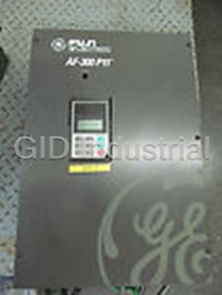


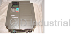
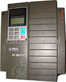


What they say about us
FANTASTIC RESOURCE
One of our top priorities is maintaining our business with precision, and we are constantly looking for affiliates that can help us achieve our goal. With the aid of GID Industrial, our obsolete product management has never been more efficient. They have been a great resource to our company, and have quickly become a go-to supplier on our list!
Bucher Emhart Glass
EXCELLENT SERVICE
With our strict fundamentals and high expectations, we were surprised when we came across GID Industrial and their competitive pricing. When we approached them with our issue, they were incredibly confident in being able to provide us with a seamless solution at the best price for us. GID Industrial quickly understood our needs and provided us with excellent service, as well as fully tested product to ensure what we received would be the right fit for our company.
Fuji
HARD TO FIND A BETTER PROVIDER
Our company provides services to aid in the manufacture of technological products, such as semiconductors and flat panel displays, and often searching for distributors of obsolete product we require can waste time and money. Finding GID Industrial proved to be a great asset to our company, with cost effective solutions and superior knowledge on all of their materials, it’d be hard to find a better provider of obsolete or hard to find products.
Applied Materials
CONSISTENTLY DELIVERS QUALITY SOLUTIONS
Over the years, the equipment used in our company becomes discontinued, but they’re still of great use to us and our customers. Once these products are no longer available through the manufacturer, finding a reliable, quick supplier is a necessity, and luckily for us, GID Industrial has provided the most trustworthy, quality solutions to our obsolete component needs.
Nidec Vamco
TERRIFIC RESOURCE
This company has been a terrific help to us (I work for Trican Well Service) in sourcing the Micron Ram Memory we needed for our Siemens computers. Great service! And great pricing! I know when the product is shipping and when it will arrive, all the way through the ordering process.
Trican Well Service
GO TO SOURCE
When I can't find an obsolete part, I first call GID and they'll come up with my parts every time. Great customer service and follow up as well. Scott emails me from time to time to touch base and see if we're having trouble finding something.....which is often with our 25 yr old equipment.
ConAgra Foods