

 Manufacturers
FUJI ELECTRIC FVR-E11

Description
Fuji Electric FVR-E11 Series Inverters. Powerful and compact inverters with dynamic torque-vector control.
Part Number
FVR-E11
Price
Request Quote
Manufacturer
FUJI ELECTRIC
Lead Time
Request Quote
Category
TBD
Datasheet

Extracted Text
MEH 404 a 1 owerful, compact inverters supported by cuttingedge technology. Dynamic torque-vector control promises optimum motor control. P Even with a compact body size, this series has a high starting torque of 200% at 0.5Hz and motor wow in the low speed range is suppressed to approximately half that of conventional inverters. Equipped with intelligent functions such as automatic energy-saving, PID control, auto-tuning, and RS485 communication, and enhanced maintenance/protection functions such as inrush-current suppression and lifetime early warning. 1.Dynamic torque-vector control Dynamic torque-vector control system performs high-speed calculation to determine the required motor power for the load status. Our exclusive technology promises optimal control of voltage and current vectors for maximum output torque. High starting torque of 200% at 0.5Hz Securely used for heavy load such as conveyance of lifting and traversing. Also available for the second motor by changeover operation. Torque characteristics 300 200 100 Motor speed 0 [r/min] 1000 2000 -100 -200 -300 2 Torque[%] 70mm Trip-free operation The remarkably improved current limiting 2. Compact function (Automatic deceleration, stall prevention) provides continuous stable Miniaturization of operation even for an impact load. minimum level in the class Compared to the conventional 200 Short-time operation torque 100% of output torque (with dynamic torque-vector control) refers to the rated FVR-E9S series, the volume is torque of the motor driven at 60Hz reduced to approximately 70%. Continuous operation torque (three-phase 200V, 0.75kW). (with dynamic torque-vector control) 100 Uniform height dimension 50 All models up to 3.7kW have a uniform height of 0 1 6 60 120 130mm, which makes it easy to design panels. Output frequency [Hz] The above graph shows an example of torque characteristics when combining FVR-E11S (at dynamic torque-vector control) with Fuji standard three-phase motor (8-type series, 4 poles). Continuous operation torque is for limits of allowable load torque for using the motor within the allowable temperature range and is not for motor output torque. The motor output torque is shown by the short-time operation torque. 130mm Reduced motor wow at low speed Fuji’s unique On-Delay compensation method reduces motor wow at low speed to approximately half of that of conventional inverters. Wow characteristics Braking resistor connectable to all models Conventional Fuji inverter Owing to a built-in braking transistor, an 0 optional braking resistor can be installed to Motor speed [r/min] FVR-E11S increase the regenerative braking capacity 0 for conveyance and transportation machines that require large braking power. 3 Output torque [%] New on-line tuning system 3. Consideration for On-line tuning to continuously check for variation of motor characteristics during peripheral devices running for high-precision speed control. This tuning function also available for a second Built-in inrush-current motor, which allows high-precision driving of suppression circuit as the second motor by changeover operation standard between two motors. The capacity of peripheral On-line tuning characteristics devices such as magnetic 70°C contactor can be minimized. 30°C Low noise Remarkably reduces influence to devices With on-line tuning such as sensors. Without on-line tuning 080 Time [min] Equipped with a terminal for connecting DC REACTOR for Continuous operation after harmonics suppression momentary power failure Minimal motor sound driving with Provided with restart mode setting; restart higher carrier frequency setting either at output frequency on power failure occurrence or at starting frequency. Selectable control meter outputs (analog/pulse changeover) PID control function Equipped with a PID control function which 24V power source for transistor can control the flow rate of fans and pumps in output an optimal manner. 4. Advanced, convenient Various frequency setting methods Keypad operation or analog input functions (4 to 20mAdc, 0 to +5Vdc, 0 to ±10Vdc, normal/inverse) Equipped automatic energy- Multistep speeds, 16-step setting (0 to 15 saving function as standard steps) and UP/DOWN control etc. Since controlling the motor losses to minimum, realizes further Equipped with RS485 interface as electric power-saving. standard Energy saving effect 100 90 When using damper 80 Energy saved 70 60 Inverter control 50 (V/f control) Energy saved 40 30 When using inverter 20 Inverter control 10 (Automatic energy-saving mode) 0 10 20 30 40 50 60 70 80 90 100 Flow rate Q [%] 4 Required power P [%] Motor speed [r/min] Temperature [°C] Various indications on the keypad panel 5. Wide variation Indicates output frequency, output current, output voltage, motor speed, trip history, etc. Line-up up to 7.5kW Extensively arranged three- phase 200V and 400V series, facilitating the unification of applying inverters to machines and equipment. Single-phase 200V series (2.2kW or Simple wiring smaller) Only requires removing covers of the main circuit and control circuit terminal blocks adopting screw terminal, without detaching the keypad panel. Simple function setting by copy unit (Option) The optional copy unit (CP-E11S) can set functions in plural inverters in a lump, 6. Protective functions, which can be commonly used for FUJI’s C11S series. Maintenance Indication of main circuit 8. Global products capacitor life and accumulated operation time Conforms to major world safety standards: Cooling fan stop operation possible UL, cUL, TÜV, EN (CE marking) Overheat early warning of heat sink Complied with EMC Directive Protective function of input/output phase loss (Emission) when connected to optional EMC compliance filter 7. Easy operation and wiringConnection to field bus: Profibus-DP, Interbus-S, DeviceNet, Modbus Plus, CAN Open (Option) Simple remote control Remote control is EU region North America/Canada available by removing keypad panel and using an optional extension cable EU Directive (CE marking) TÜV approval UL, cUL (CBR-5S). 5 Variation Wide range of inverters: single-phase 200V, three-phase 400V, and three-phase 200V. Nominal applied Single-phase 200V series Three-phase 400V series Three-phase 200V series motors [kW] 0.1 FVR0.1E11S-7JE FVR0.1E11S-2JE 0.2 FVR0.2E11S-7JE FVR0.2E11S-2JE 0.4 FVR0.4E11S-7JE FVR0.4E11S-4JE FVR0.4E11S-2JE 0.75 FVR0.75E11S-7JE FVR0.75E11S-4JE FVR0.75E11S-2JE 1.5 FVR1.5E11S-7JE FVR1.5E11S-4JE FVR1.5E11S-2JE 2.2 FVR2.2E11S-7JE FVR2.2E11S-4JE FVR2.2E11S-2JE 3.7 FVR3.7E11S-4JE FVR3.7E11S-2JE 5.5 FVR5.5E11S-4JE FVR5.5E11S-2JE 7.5 FVR7.5E11S-4JE FVR7.5E11S-2JE How to read the model number Code Application range E Compact, general industrial Code Enclosure machines S Standard Code Series name FVR FVR series Code Version JE JE FVR 0.1 E 11 S - 7 JE Code Nominal applied motors [kW] Code Input power source 0.1 0.1kW 7 Single-phase 200V Code Developed inverter series 4 Three-phase 400V 0.2 0.2kW 11 11 series 2 Three-phase 200V 0.4 0.4kW 0.75 0.75kW 1.5 1.5kW 2.2 2.2kW 3.7 3.7kW 5.5 5.5kW 7.5 7.5kW 6 6 Application FVR-E11S series. For almost all industrial plant and equipment areas. Fans Electric pumps Food processing machines • Air conditioning system • Tankless water-supply • Dryer system • Food mixer • Boiler fan • Submersible pump • Food slicer • Fans for controlling • Vacuum pump • Grain processing furnace temperature • Fountain pump machine • Roof fans controlled as • Cooling water pump • Tea manufacturing a group • Circulating hot water machine • Refrigerator pump • Rice milling machine • Built-in blower in a film- • Well pump manufacturing machine • Pump for agricultural • Fan for separator water storage • Cooling-tower fans • Constant-flow pump • Ventilating fans • Sludge pump • Air-conditioning Textile/paper equipment making machinery • Spinning machine • Knitting machine • Textile printing machine • Industrial sewing machine Conveyance • Slitter machinery • Crane (traveling, traversing, hoisting) • Automated warehouse • Conveyor (belt, chain, screw, roller) Packaging • Lift machinery • Car parking system • Elevator, escalator • Individual packing / • Automatic door inner packing • Shutter • Packing machine • Speed changer • Outer packing machine Chemical Machine tools Other machinery machinery/wood • Boring machine • Automated feed / working machines • Winding machine medicine mixing • Press machine • Fluids mixing machine • Turntable • Commercial-use • Centrifugal separator • Work positioning unit washing machine • Coating machine • PC board drilling • Offset printing press • Take-up roller machine • Bookbinding machine • Router machine • Car washing machine • Sanding machine • Shredder • Planing machine • Dishwasher • Test equipment 7 7 Standard Specifications Single-phase 200V series Type FVR¤¤¤E11S-7JE 0.1 0.2 0.4 0.75 1.5 2.2 Nominal applied motor *1) kW 0.1 0.2 0.4 0.75 1.5 2.2 0.30 0.57 1.1 1.9 3.0 4.1 Rated capacity *2) kVA 3-phase 200V/50Hz 200, 220, 230V/60Hz Rated voltage *3) V Rated current *4) A 0.8 1.5 3.0 5.0 8.0 11 Output (0.7) (1.4) (2.5) (4.0) (7.0) (10) ratings Overload capability 150% of rated current for 1min. 200% of rated current for 0.5s Rated frequency Hz 50, 60Hz Phases, Voltage, Frequency 1-phase 200 to 240V 50/60Hz Voltage / frequency variations Voltage: +10 to –10% (Voltage unbalance *5): 2% or less) Frequency: +5 to –5% When the input voltage is 165V or more, the inverter can be operated continuously. Momentary voltage dip capability *6) When the input voltage drops below 165V from rated voltage, the inverter can be operated for 15ms. Input The smooth recovery mode is selectable (by Auto-restart function). ratings Rated current *7) (with DCR) 1.2 2.0 3.5 6.5 11.8 17.7 A (without DCR) 2.3 3.9 6.4 11.4 19.8 28.5 Required power 0.3 0.4 0.7 1.3 2.4 3.6 supply capacity *9) kVA Control Starting torque 200% (with Dynamic torque-vector control selected) Braking torque (Standard) *10) 100 70 40 Braking 150 Braking torque (Using options) DC injection braking Starting frequency: 0.0 to 60.0Hz Braking time: 0.0 to 30.0s Braking level: 0 to 100% of rated current Enclosure (IEC 60529) IP 20 Cooling method Natural cooling Fan cooling -UL/cUL -Low Voltage Directive -EMC Directive -TÜV Standards -IEC 61800-2 (Ratings, specifications for low voltage adjustable frequency a.c. power drive systems) -IEC 61800-3 (EMC product standard including specific test methods) Mass kg 0.6 0.7 0.7 1.2 1.8 1.9 Three-phase 400V series Type FVR¤¤¤E11S-4JE 0.4 0.75 1.5 2.2 3.7 5.5 7.5 Nominal applied motor *1) kW 0.4 0.75 1.5 2.2 3.7 5.5 7.5 Rated capacity *2) kVA 1.1 1.9 2.8 4.1 6.8 9.9 13 Rated voltage *3) V 3-phase 380, 400, 415V/50Hz, 380, 400, 440, 460V/60Hz Output Rated current *4) A 1.5 2.5 3.7 5.5 9.0 13 18 ratings (1.4) (2.1) (3.7) (5.3) (8.7) (12) (16) Overload capability 150% of rated current for 1min. 200% of rated current for 0.5s Rated frequency Hz 50, 60Hz 3-phase 380 to 480V 50/60Hz Phases, Voltage, Frequency Voltage / frequency variations Voltage: +10 to –15% (Voltage unbalance *5): 2% or less) Frequency: +5 to –5% Momentary voltage dip capability *6) When the input voltage is 300V or more, the inverter can be operated continuously. When the input voltage drops below 300V from rated voltage, the inverter can be operated for 15ms. Input The smooth recovery mode is selectable (by Auto-restart function). ratings Rated current *7) (with DCR) 0.82 1.5 2.9 4.2 7.1 10.0 13.5 A (without DCR) *8) 1.8 3.5 6.2 9.2 14.9 21.5 27.9 Required power 0.6 1.1 2.1 3.0 5.0 7.0 9.4 supply capacity *9) kVA Control Starting torque 200% (with Dynamic torque-vector control selected) 70 40 20 Braking torque (Standatd) *10) Braking Braking torque (Using options) 150 DC injection braking Starting frequency: 0.0 to 60.0Hz Braking time: 0.0 to 30.0s Braking level: 0 to 100% of rated current Enclosure (IEC 60529) IP 20 Natural cooling Fan cooling Cooling method -UL/cUL -Low Voltage Directive -EMC Directive -TÜV Standards -IEC 61800-2 (Ratings, specifications for low voltage adjustable frequency a.c. power drive systems) -IEC 61800-3 (EMC product standard including specific test methods) Mass kg 1.1 1.2 1.3 1.4 1.9 4.5 4.5 NOTES: *1) Normal applied motor indicates standard FUJI 4P motor. *2) Inverter output capacity (kVA) at 440V in 400V series, 220V in 200V series. *3) Output voltage cannot exceed the power supply voltage. *4) Current derating may be required in case of low impedance loads such as high frequency motor. Use the inverter at the current ( ) or below where carrier frequency setting is higher than 4kHz (F26: 4 to 15) or the amb. temp. is 40°C or higher. *5) Refer to the IEC 61800-3 (5.2.3). *6) Tested at standard load condition (85% load). *7) This value is under FUJI original calculation method. (Refer to the Technical Information.) *8) Calculated value when connected to power supply of 500kVA. *9) When optional power-factor correcting DC REACTOR (DCR) is used. *10) With a nominal applied motor, this value is average torque when the motor decelerates and stops from 60Hz. (It may change according to motor loss.) 8 Three-phase 200V series Type FVR¤¤¤E11S-2JE 0.1 0.2 0.4 0.75 1.5 2.2 3.7 5.5 7.5 Nominal applied motor *1) kW 0.1 0.2 0.4 0.75 1.5 2.2 3.7 5.5 7.5 Rated capacity *2) kVA 0.30 0.57 1.1 1.9 3.0 4.2 6.5 9.5 12.5 Rated voltage *3) V 3-phase 200V/50Hz 200, 220, 230V/60Hz Rated current *4) A 0.8 1.5 3.0 5.0 8.0 11 17 25 33 Output (0.7) (1.4) (2.5) (4.0) (7.0) (10) (16.5) (23.5) (31) ratings 150% of rated current for 1min. 200% of rated current for 0.5s Overload capability 50, 60Hz Rated frequency Hz 3-phase 200 to 230V 50/60Hz Phases, Voltage, Frequency Voltage / frequency variations Voltage: +10 to –15% (Voltage unbalance *5): 2% or less) Frequency: +5 to –5% When the input voltage is 165V or more, the inverter can be operated continuously. Momentary voltage dip capability *6) When the input voltage drops below 165V from rated voltage, the inverter can be operated for 15ms. Input The smooth recovery mode is selectable (by Auto-restart function). ratings 0.59 0.94 1.6 3.1 5.7 8.3 14.0 19.7 26.9 Rated current *7) (with DCR) A (without DCR) 1.1 1.8 3.4 6.4 11.1 16.1 25.5 40.8 52.6 Required power 0.3 0.4 0.6 1.1 2.0 2.9 4.9 6.9 9.4 supply capacity *8) kVA Control Starting torque 200% (with Dynamic torque-vector control selected) Braking torque (Standard) *9) 100 70 40 20 150 Braking Braking torque (Using options) DC injection braking Starting frequency: 0.0 to 60.0Hz Braking time: 0.0 to 30.0s Braking level: 0 to 100% of rated current Enclosure (IEC 60529) IP 20 Cooling method Natural cooling Fan cooling -UL/cUL -Low Voltage Directive -EMC Directive -TÜV Standards -IEC 61800-2 (Ratings, specifications for low voltage adjustable frequency a.c. power drive systems) -IEC 61800-3 (EMC product standard including specific test methods) Mass kg 0.6 0.6 0.7 0.8 1.3 1.3 2.0 4.5 4.5 NOTES: *1) Normal applied motor indicates standard FUJI 4P motor. *2) Inverter output capacity (kVA) at 220V in 200V series. *3) Output voltage cannot exceed the power supply voltage. *4) Current derating may be required in case of low impedance loads such as high frequency motor. Use the inverter at the current ( ) or below where carrier frequency setting is higher than 4kHz (F26: 4 to 15) or the amb. temp. is 40°C or higher. *5) Refer to the IEC 61800-3 (5.2.3). *6) Tested at standard load condition (85% load). *7) This value is under FUJI original calculation method. (Refer to the Technical Information.) *8) When optional power-factor correcting DC REACTOR (DCR) is used. *9) With a nominal applied motor, this value is average torque when the motor decelerates and stops from 60Hz. (It may change according to motor loss.) Common Specifications Item Explanation Output Maximum frequency 50 to 400Hz *1) frequency Base frequency 25 to 400Hz Starting frequency 0.1 to 60.0Hz, Holding time: 0.0 to 10.0s Carrier frequency *2) 0.75 to 15kHz Accuracy (Stability) • Analog setting : ±0.2% of Maximum frequency (at 25±10°C) • Digital setting : ±0.01% of Maximum frequency (at –10 to +50°C) Setting resolution • Analog setting : 1/3000 of Maximum frequency ex.) 0.02Hz at 60Hz, 0.04Hz at 120Hz, 0.15Hz at 400Hz • Digital setting : 0.01Hz at Maximum frequency of up to 99.99Hz (0.1Hz at Maximum frequency of 100.0Hz and above) • LINK setting : • 1/20000 of Maximum frequency ex.) 0.003Hz at 60Hz, 0.006Hz at 120Hz, 0.02Hz at 400Hz • 0.01Hz (Fixed) Control Control method • V/f control (Sinusoidal PWM control) • Dynamic torque-vector control (Sinusoidal PWM control) Voltage / freq. (V/f) characteristic Adjustable at base and maximum frequency, with AVR control : 160 to 480V (400V series), 80 to 240V (200V series) Torque boost Selectable by load characteristics: Constant torque load (Auto/manual), Variable torque load (Manual) Operation method • KEYPAD operation : key, key • Digital input signal operation : FWD or REV command, Coast-to-stop command, etc. • LINK operation : RS485 (Standard) Profibus-DP, Interbus-S, DeviceNet, Modbus Plus, CAN Open (Option) Frequency setting • KEYPAD operation: or key (Frequency command) • External potentiometer (*) : 1 to 5kΩ • Analog input : 0 to +10V DC (0 to +5V DC), 4 to 20mA DC (Reversible) 0 to ±10V DC (0 to ±5V DC) ....Reversible operation by polarized signal can be selected. (Inverse) +10 to 0V DC, 20 to 4mA DC......Inverse mode operation can be selected. • UP/DOWN control : Output frequency increases when UP signal is ON, and decreases when DOWN signal is ON. • Multistep frequency : Up to 16 different frequencies can be selected by digital input signal. • LINK operation : RS485 (Standard) Profibus-DP, Interbus-S, DeviceNet, Modbus Plus, CAN Open (Option) Running status signal Transistor output (2 points) : RUN, FAR, FDT, OL, LU, TL, etc. Relay output (1 point) : Alarm output (for any fault) Analog (or pulse) output (1 point) : Output frequency, Output current, Output torque, etc. Acceleration / Deceleration time 0.01 to 3600s : • Independently adjustable acceleration and deceleration • 4 different times are selectable. Mode select : Linear, S-curve (weak), S-curve (strong), Non-linear Frequency limiter High and Low limiters can be preset. Bias frequency Bias frequency can be preset. Gain for frequency setting Gain for frequency setting can be preset. (0.0 to 200.0%) ex.) Analog input 0 to +5V DC with 200% gain results in maximum frequency at 5V DC. NOTES: (*) Option *1) For application at 120Hz or above, please contact FUJI. *2) Inverter may automatically reduce carrier frequency, in accordance with ambient temperature or output current for protecting inverter. 9 Setting Item Explanation Control Jump frequency control Jump frequency (3 points) and its common jump hysteresis width (0 to 30Hz) can be preset. Rotating motor pick up (Flying start) A rotating motor (including inverse rotating mode) can be smoothly picked up without stopping the motor (speed search method). Auto-restart after momentary power Automatic restart is available without stopping motor after a momentary power failure (speed search method). When "Smooth recovery" mode is failure selected, the motor speed drop is held minimum. (The inverter searches the motor speed, and smoothly returns to setting frequency. Even if the motor circuit is temporarily opened, the inverter operates without a hitch. ) Slip compensation The inverter output frequency is controlled according to the load torque to keep motor speed constant. When the value is set at "0.00" and "Torque-vector" is set at "active", the compensation value automatically selects the Fuji standard motor. Slip compensation can be preset for the second motor. Droop operation The motor speed droops in proportion to load torque (–9.9 to 0.0Hz). Torque limiter • When the motor torque reaches a preset limiting level, this function automatically adjusts the output frequency to prevent the inverter from tripping due to an overcurrent. • Torque limiter 1 and 2 can be individually set, and are selectable with a digital input signal. PID control This function can control flowrate, pressure, etc. (with an analog feedback signal.) • Reference • KEYPAD operation ( or key) : 0.0 to 100.0% signal • Voltage input (Terminal 12 ) : 0 to +10V DC • Current input (Terminal C1 ) : 4 to 20mA DC • Multistep frequency setting : Setting freq. / Max. freq. X 100 (%) • RS485 : Setting freq. / Max. freq. X 100 (%) • • Feedback signal Terminal 12 (0 to +10V DC or +10 to 0V DC) • Terminal C1 (4 to 20mA DC or 20 to 4mA DC) Automatic deceleration Torque limiter 1 (Braking) is set at "F41: 0" (Same as Torque limiter 2 (Braking) ). • In deceleration : The deceleration time is automatically extended up to 3 times the setting time for tripless operation even if braking resistor not used. • In constant speed operation : Based on regenerative energy, the frequency is increased and tripless operation is active. Second motor's setting This function is used for two motors switching operation. • The second motor’s V/f characteristics (base and maximum frequency) can be preset. • The second motor’s circuit parameter can be preset. Torque-vector control can be applied to both motors. Energy saving operation This function minimizes inverter and motor losses at light load. Fan stop operation This function is used for silent operation or extending the fan's lifetime. Indication Operation mode (Running) • Output frequency (Hz) • Constant rate of feeding time (LED monitor) • • Setting frequency (Hz) Line speed (m/min) • • Output current (A) PID reference value • • PID reference value (remote) Output voltage (V) • Motor synchronous speed (r/min) • PID feedback value Stopping Selected setting value or output value Trip mode Displays the cause of trip by codes as follows. • dBH (Overheating at DB circuit) • • OC1 (Overcurrent during acceleration) OL1 (Motor 1 overload) • • OC2 (Overcurrent during deceleration) OL2 (Motor 2 overload) • • OLU (Inverter unit overload) OC3 (Overcurrent during running at constant speed) • Lin (Input phase loss) • Er1 (Memory error) • • OU1 (Overvoltage during acceleration) Er2 (KEYPAD panel communication error) • • OU2 (Overvoltage during deceleration) Er3 (CPU error) • OU3 (Overvoltage during running at constant speed) • Er4 (Option error) • LU (Undervoltage) • Er5 (Option error) • OH1 (Overheating at heat sink) • Er7 (Output phase loss error, impedance imbalance) • • OH2 (External thermal relay tripped) Er8 (RS485 error) • Running or trip mode Trip history: Cause of trip by code (Even when main power supply is off, trip history data of the last 4 trips are retained.) Charge lamp When the DC link circuit voltage is higher than 50V, the charge lamp is ON. Protection Overload Protects the inverter by electronic thermal and detection of inverter temperature. Overvoltage Detects DC link circuit overvoltage,and stops the inverter. (400V series: 800V DC, 200V series: 400V DC) Incoming surge Protects the inverter against surge voltage between the main circuit power line and the ground. Undervoltage Detects DC link circuit undervoltage,and stops the inverter. (400V series: 400V DC, 200V series: 200V DC) Input phase loss Phase loss protection for power line input. Overheating Protects the inverter by detection of inverter temperature. Short-circuit Short-circuit protection for inverter output circuit Ground fault • Ground fault protection for inverter output circuit Motor overload • Electronic thermal overload relay can be selected for standard motor or inverter motor • Thermal time constant (0.5 to 10.0 minutes) can be preset for a special motor. • The second motor's electronic thermal overload relay can be preset for 2-motor changeover operation. *(overlod early warning) • Outputs a warning signal at preset level before inverter trip. DB resistor overheating • Prevents DB resistor overheating by internal electronic thermal overload relay. (The inverter stops electricity discharge operation to protect the DB resistor.) Stall prevention • Controls the output frequency to prevent (overcurrent) trip when the output current exceeds the limit value during acceleration. • Lowers the output frequency to hold almost constant torque when the output current exceeds the limit value during operation at constant speed. • Controls the output frequency to prevent (overvoltage) trip when the DC link circuit voltage exceeds the limit value during deceleration. Output phase loss When the inverter executes tuning, detects each phase impedance imbalance. Motor protection by PTC thermistor When the motor temperature exceeds allowable value, the inverter trips automatically. Auto reset When the inverter is tripped, it resets automatically and restarts. Installation location Condition Free from corrosive gases, flammable gases, oil mist, dusts, and direct sunlight. Indoor use only. Pollution degree 2 for Low Voltage Directive. (Installation Altitude 1000m or less. Applicable to 3000m with power derating (–10%/1000m) and Ambient temperature –10 to +50 °C operation) Ambient humidity 5 to 95%RH (non-condensing) 2 Vibration 3mm at from 2 to less than 9Hz, 9.8m/s at from 9 to less than 20Hz 2 2 2m/s at from 20 to less than 55Hz, 1m/s at from 55 to less than 200Hz • • Storage condition Temperature : –25 to +65 °C Humidity : 5 to 95%RH (non-condensing) 10 Basic Wiring Diagram Keypad panel Operation The following diagram is for reference only. For detailed wiring diagrams, refer to the relevant instruction manual. Operation using the factory settings Power supply Connect the inverter to the power supply and the motor. Then, turn L1/L 1-phase 200 to 240V L2/N on the power to enable variable speed operation. 50/60Hz MCCB or * [ Operation method ] ELCB Motor 1. Run/Stop ................ Press or key on the keypad panel. Power supply * L1/R U 3-phase M 400 to 480V L2/S V 2. Setting frequency .... Press or key on the keypad panel. 50/60Hz L3/T W or MCCB 200 to 230V * (*5) G G or 50/60Hz NOTES: ELCB P1 P1 *1) When connecting an optional DC REACTOR, remove the P (+) P (+) jumper wire that connects the terminals [P1] and [P+]. (*1) E 13 DB POT power supply *2) Keep the control circuit wires at least 100mm away from the N (-) 12 Analog input Voltage input main circuit wires and put them in separate ducts to prevent Where DC REACTOR * 11 is used noise and resultant malfunctions. When control wiring crosses C1 Current input 30C 30 the main wiring, ensure that they cross each other at right 30B angles. Alarm output (for any fault) PLC *3) For the wiring of the control circuit, use shielded or twisted FWD 30A wires with the shortest possible length. (When using shielded REV P24 wires, connect one end of the shields to the inverter ground X1 Y2 Transistor output terminal and leave the other end free.) X2 Digital input Y1 X3 *4) If there is a magnetic contactor or a solenoid close to the CME X4 inverter, connect a surge suppresser to the coil in parallel X5 connection. Keep the wiring length to a minimum. CM Analog/ *5) Terminal for grounding the motor. pulse changeover Analog/pulse output FM switch Connect it, if necessary. Option * External signal input Operation The following diagram is for reference only. For detailed wiring diagrams, refer to the relevant instruction manual. External braking resistor (DB) * Run/Stop operation and frequency setting through external signals 2 (CM) 1 P DB (THR) When “1” is set at , you can set a frequency by using an Power supply G L1/L (*4) 1-phase 200 to 240V input signal for 0 to 10V DC. When “2” is set at , you can L2/N 50/60Hz MCCB or DB P (+) * set a frequency by using an input signal for 4 to 20mA DC. In ELCB both cases, set “1” at . Motor Power supply L1/R * U 3-phase L2/S V M 400 to 480V 50/60Hz NOTES: L3/T W or MCCB * 200 to 230V G G (*5) *1) When connecting an optional DC REACTOR, remove the or 50/60Hz ELCB jumper wire that connects the terminals [P1] and [P+]. P1 P1 *2) If there is a magnetic contactor or a solenoid close to the P (+) P (+) (*1) inverter, connect a surge suppresser to the coil in parallel E 3 DB 13 2 connection. Keep the wiring length to a minimum. Voltage input N (-) 12 (0 to +10V DC) Where DC REACTOR * 1 *3) For the wiring of the control circuit, use shielded or twisted Analog input 11 is used wires with the shortest possible length. When using shielded Current input 30C 30 (4 to 20mA DC) C1 wires, connect the shields to the inverter ground terminal. 30B Alarm output (for any fault) *4) (THR) terminal function can be used by assigning code “8” 30A (External fault) to any of X1 to X5 terminal (function code PLC Forward command FWD E01 to E05). Reverse REV *5) Terminal for grounding the motor. command X1 P24 Digital input Connect it, if necessary. X2 Y2 Transistor output X3 Y1 X4 Pulse CME FM ( Digital freq. meter) X5 counter * CM Analog/ Analog monitor To terminal 11 pulse changeover FM switch Analog meter Option To terminal 11 * 11 Terminal Functions Terminal Functions Symbol Terminal name Function Remarks Func. code Main L1/R, L2/S, Power input Connect a 3-phase power supply. circuit L3/T L1/L, L2/N Power input Connect a 1-phase power supply. U, V, W Inverter output Connect a 3-phase induction motor. P1, P(+) For DC REACTOR Connect the DC REACTOR for power-factor correcting or harmonic current reducing. DC REACTOR: Option P(+), N(-) For DC link circuit Used for DC bus connection system. P(+), DB For EXTERNAL Connect the EXTERNAL BRAKING RESISTOR (Option) BRAKING RESISTOR G Grounding Ground terminal for inverter chassis (housing). Analog 13 Potentiometer +10V DC power supply for frequency setting POT (POT: 1 to 5kΩ) • Allowable maximum output current : 10mA input power supply • 12 Voltage input • Input impedance: 22kΩ F01, C30 0 to +10V DC/0 to 100% (0 to +5V DC/0 to 100% ) • • Allowable maximum input voltage: ±15V DC Reversible operation can be selected by function setting. • If input voltage is 10 to 15V DC, the inverter estimates 0 to ±10V DC /0 to ±100% (0 to ±5V DC/0 to ±100%) it to10V DC. (PID control) Used for PID control reference signal or feedback signal. F01, H21 • • C1 Current input 4 to 20mA DC/0 to 100% Input impedance: 250Ω F01 Used for PID control reference signal or feedback signal. F01, H21 (PID control) (PTC thermistor input) The PTC thermistor (for motor protection) can be connected to terminal C1 - 11. H26, H27 11 Common Common for analog signal Isolated from terminal CME and CM. Digital FWD Forward operation FWD: ON ..... The motor runs in the forward direction. When FWD and REV are simultaneously ON, the motor F02 FWD: OFF ..... The motor decelerates and stops. decelerates and stops. input command REV Reverse operation REV: ON ..... The motor runs in the reverse direction. REV: OFF ..... The motor decelerates and stops. command X1 Digital input 1 These terminals can be preset as follows. • E01 to E05 ON state maximum input voltage: 2V (maximum source current : 5mA) X2 Digital input 2 • OFF state maximum terminal voltage: 22 to 27V X3 Digital input 3 (allowable maximum leakage current: 0.5mA) X4 Digital input 4 X5 Digital input 5 (SS1) Multistep freq. (SS1) : 2 (0, 1) different frequencies are selectable. Frequency 0 is set by F01 (or C30). C05 to C19 (SS2) selection (SS1,SS2) : 4 (0 to 3) different frequencies are selectable. (All signals of SS1 to SS8 are OFF) (SS4) (SS1,SS2,SS4) : 8 (0 to 7) different frequencies are selectable. (SS8) (SS1,SS2,SS4,SS8) : 16 (0 to 15) different frequencies are selectable. (RT1) ACC / DEC time selection (RT1) : 2 (0, 1) different ACC / DEC times are selectable. Time 0 is set by F07/F08. F07, F08 E10, E11 (HLD) 3-wire operation Used for 3-wire operation. stop command (HLD): ON ..... The inverter self-holds FWD or REV signal. (HLD): OFF ..... The inverter releases self-holding. (BX) Coast-to-stop (BX): ON ..... Motor will coast-to-stop. (No alarm signal will be output.) • H11 The motor restarts from 0Hz by turning off BX with the command operation command (FWD or REV) ON. • Assigned to terminal X4 at factory setting. (RST) Alarm reset (RST): ON ..... Faults are reset. (This signal should be held for more than 0.1s.) • During normal operating, this signal is ignored. • Assigned to X5 at factory setting. (THR) Trip command (THR): OFF ..... "OH2 trip" occurs and motor will coast-to-stop. This alarm signal is held internally. (External fault) (Hz2/Hz1) Freq. set 2 / (Hz2/Hz1): ON ..... Freq. set 2 is effective. If this signal is changed while the inverter is running, F01 / C30 Freq. set 1 the signal is effective only after the inverter stops. (M2/M1) Motor 2 / Motor 1 (M2/M1): ON ..... The motor circuit parameter and V/f characteristics are changed If this signal is changed while the inverter is running, P01 to P10 / to the second motor's ones. the signal is effective only after the inverter stops. A10 to A19 (DCBRK) DC brake command (DCBRK): ON ..... The DC injection brake is effective. (In the inverter deceleration mode) If the operation command(FWD/REV) is input while DC braking F20 to F22 is effective, the operation command (FWD/REV) has priority. (TL2/TL1) Torque limiter 2 / (TL2/TL1): ON ..... Torque limiter 2 is effective. F40, F41 / Torque limiter 1 E16, E17 (UP) UP command (UP): ON ..... The output frequency increases. When UP and DOWN commands are simultaneously F01, C30 ON, DOWN signal is effective. (DOWN) DOWN command (DOWN): ON ..... The output frequency decreases. • The output frequency change rate is determined by ACC / DEC time. • Restarting frequency can be selected from 0Hz or setting value at the time of stop. (WE-KP) Write enable for KEYPAD (WE-KP): ON ..... The data is changed by KEYPAD. (Hz/PID) PID control cancel (Hz/PID): ON ..... The PID control is canceled, and frequency setting by KEYPAD H20 to H25 ( or )is effective. (IVS) Inverse mode changeover (IVS): ON ..... Inverse mode is effective in analog signal input. If this signal is changed while the inverter is running, the signal F01, C30 is effective only after the inverter stops. (LE) Link enable (RS485, Bus) (LE): ON ..... The link opereation is effective. Used to switch operation between ordinary RS485: Standard, Bus: Option H30 operation and link operation to communication. PLC PLC terminal Connect PLC power supply to avoid malfunction of the inverter that has SINK type digital input, when PLC power supply is off. CM Common Common for digital signal Isolated from CME and 11. 12 Terminal Functions Symbol Terminal name Function Remarks Func. code Analog FM Analog monitor Output voltage (0 to 10V DC) is proportional to selected function’s value as follows. Allowable maximum output current: 2mA F30, F31 output The proportional coefficient and bias value can be preset. • Output frequency 1 (Before slip compensation) (0 to max. frequency) • Output frequency 2 (After slip compensation) (0 to max. frequency) • Output current (0 to 200%) • Output voltage (0 to 200%) • Output torque (0 to 200%) • Load factor (0 to 200%) • Input power (0 to 200%) • PID feedback value (0 to 100%) • DC link circuit voltage (0 to 1000V) (11) (Common) Pulse FM Pulse rate monitor • Allowable maximum output current : 2mA F33 to F35 Pulse rate mode : Pulse rate is proportional to selected function’s value* (50% duty pulse) output • Average voltage mode : Average voltage is proportional to selected function’s value* (2670p/s pulse width control) * Kinds of function to be output is same as those of analog output (FM). (11) (Common) Transistor P24 DC voltage supply Power supply for transistor output load. (+24V DC, 50mA max.) output Y1 Transistor output 1 Output the selected signals from the following items. • ON state maximum output voltage : 2V E20, E21 (Allowable maximum sink current : 50mA) Y2 Transistor output 2 • OFF state maximum leakage current : 0.1mA (Allowable maximum voltage : 27V) (RUN) Inverter running Outputs ON signal when the output frequency is higher than starting frequency. (FAR) Frequency equivalence Outputs ON signal when the difference between output frequency and setting frequency is E30 signal smaller than FAR hysteresis width. (FDT) Frequency level detection Outputs ON signal by comparison of output frequency and preset value (level and hysteresis). E31, E32 (LU) Undervoltage Outputs ON signal when the inverter stops by undervoltage while the operation command is ON. detection signal (B/D) Torque polarity Outputs ON signal in braking or stopping mode, and OFF signal in driving mode. (TL) Torque limiting Outputs ON signal when the inverter is in torque-limiting mode. (IPF) Auto-restarting Outputs ON signal during auto restart operation (Instantaneous power failure) mode. (including "restart time") (OL) Overload early warning • Outputs ON signal when the electronic thermal value is higher than preset alarm level. E33 to E35 • Outputs ON signal when the output current value is higher than preset alarm level. CME Common (transistor Common for transistor output signal. Isolated from terminals CM and 11. output) Relay 30A, 30B Alarm relay output Outputs a contact signal when a protective function is activated. • Contact rating : F36 output 30C 250V AC, 0.3A, cosş=0.3 Changeable exciting mode active or non-exciting mode active by function "F36". 48V DC, 0.5A, non-inductive (for LVD) 42V DC, 0.5A, non-inductive (for UL/cUL) LINK RS485 I/O terminal Connect the RS485 link signal. Terminal Arrangement Main circuit Control circuit terminals terminals P R G RUN RESET FUNC DATA STOP FVR-E11 WARNING 30A 30B Y1 C1 FM X1 X2 X3 X4 X5 PLC P R G P R G RUN P R G RESET 30C Y2 CME 11 12 13 CM FWD REV CM P24 RESET RUN RUN RESET FUNC FUNC FUNC DATA STOP STOP DATA STOP DATA FVR-E11 FVR-E11 FVR-E11 WARNING WARNING WARNING L1/R L2/S L3/T DB P1 P(+) N(-) U V W 30A 30B Y1 C1 FM X1 X2 X3 X4 X5 PLC 30A 30B Y1 C1 FM X1 X2 X3 X4 X5 PLC 30C Y2 CME 11 12 13 CM FWD REV CM P24 30C Y2 CME 11 12 13 CM FWD REV CM P24 30A 30B Y1 C1 FM X1 X2 X3 X4 X5 PLC 30C Y2 CME 11 12 13 CM FWD REV CM P24 DB P1 P(+) N(-) DB P1 P(+) N(-) G G L1/R L2/S L3/T U V W G L1/R L2/S L3/T U V W G G L1/R L2/S L3/T DB P1 P(+) N(-) U V W G G G (4JE, 2JE) (4JE, 2JE) (4JE, 2JE) DB P1 P(+) N(-) DB P1 P(+) N(-) L1/L L2/N U V W G L1/R L2/N U V W G G L1/R L2/N DB P1 P(+) N(-) U V W G G G (7JE) (7JE) (7JE) FVR0.1, 0.2, 0.4E11S-7JE FVR0.75E11S-7JE FVR1.5, 2.2E11S-7JE FVR5.5, 7.5E11S-4JE FVR0.1 to 0.75E11S-2JE FVR0.4 to 2.2E11S-4JE FVR3.7E11S-4JE FVR5.5, 7.5E11S-2JE FVR1.5, 2.2E11S-2JE FVR3.7E11S-2JE 13 Keypad Panel Functions and Operations Keypad panel LED monitor Operation mode indication In Operation mode: RUN : Displays the setting frequency, output current, This LED goes on during operating. voltage, motor speed, or line speed. PANEL CONTROL : In Trip mode: When Function code is set at , Displays code indicating the cause of trip. , or (Keypad operation), this LED goes on. Unit indication Displays the unit of the value shown on the LED monitor. Program/Reset key Run key Switches between operation Starts the inverter. mode and program mode. In Stop mode: When tripped: Invalid when the function code Releases the trip-stop state and is set at changes to operation mode. (external operation). Stop key Function/Data select key Stops the inverter. Changes the displayed values of LED monitor, selects and In Operation mode: stores the function codes and data codes. Invalid when the function code is set at (external operation). Up/Down keys In Operation mode: Increases or decreases the frequency or motor speed. In Program mode: Increases or decreases function code number and data set value. Keypad panel operation 1. Turn on the power supply, press the or key to set the output frequency. When you press the key, the motor will run at the set frequency and with function code/data at factory shipment. When you press the key, the motor will decelerates and stops. 2. Procedure for selecting and changing function codes and data codes. The keypad panel operation how to select a function code and change its data code is explained below. q Press the key to select the program mode. w Pressing key alternates the displayed data between the function code and its data. ( ) e With data displayed, press the or key to change the data code. r Press the key to update the data for the selected function code. * In step w above, if the or key is pressed when the function code is displayed, only the function code changes sequentially (see below). ( ) 14 T he keypad panel modes are classified in the following 5 modes. Mode Program mode Program mode Stop mode Operation mode Trip mode Monitor, keys (operation stopped) (during operation) Displays the set frequency, Displays the output Displays the trip Displays the function code Displays the function code output current, output frequency, output current, content or alarm or data code. (Blinking) or data code. (Lighting) voltage, motor speed, line output voltage, motor history. (Blinking speed. (Blinking) speed, line speed. (Lighting) or lighting) Indicates the PRG mode Indicates the PRG mode Unit indication of the Unit indication of the None during stopping. during operation. above value. above value. PRG MODE PRG MODE Freq.. Hz AV Freq.. Hz AV r/min m/min r/min m/min PRG MODE PRG MODE PRG MODE Current Hz AV Current Hz AV Hz AV r/min m/min r/min m/min PRG MODE PRG MODE PRG MODE PRG MODE r/min m/min Voltage Voltage Hz AV Hz AV Lighting Monitor Hz AV Lighting Hz AV r/min m/min r/min m/min Not lit PRG MODE PRG MODE r/min m/min m/min r/min Motor Motor Hz AV Hz AV speed speed r/min m/min r/min m/min PRG MODE PRG MODE Line Line Hz AV Hz AV speed speed r/min m/min r/min m/min PRG MODE PRG MODE Constant rate Constant rate Hz AV Hz AV of feeding time of feeding time m/min r/min m/min r/min PANEL Indicates whether keypad panel operation or external signal operation. None CONTROL (ON during keypad panel operation) (Lighting) Indicates the operation Indicates during Indicates the operation Indicates during Indicates “stopping has stopped. operation. has stopped. operation. in trip mode.” RUN ( RUN not lit) ( RUN lighting) ( RUN not lit) ( RUN lighting) ( RUN lighting) Switches to the stop Changes to operation Switches to “Program Switches to “Program Releases the trip mode. mode. mode (operation mode during operation.” and switches to stopped).” “stop mode” or “operation mode.” Changes the display between function code and Shifts the value on the LED monitor and the unit of data code, stores data code, and then updates the unit indication LED. Invalid function codes. Increases/decreases Increases/decreases the Increases/decreases the setting of frequency, Displays the alarm function code number data code number and motor speed, line speed. history. Keys and data code. stores data temporary. Invalid Invalid Switches to operation Invalid Invalid mode. Invalid Switches to “stop mode” Invalid Switches to the stop Invalid or “Program mode mode. (operation stopped).” * Procedure for selecting function codes and data codes (Ex. Changing data code from to of function code ) To select other function codes, repeat the same way. ×2 Change of Change of setting frequency unit indication (digital setting) 15 Function settings The functions in the yellow boxes can be set while the inverter is running. Other functions must be set while the inverter is stopped. Fundamental Functions Function Min. Setting range Factory setting unit Code Name Basic Data protection 0 : Data change enable - 0 Functions 1 : Data protection Frequency command 1 0 : KEYPAD operation ( or key) 1 : Voltage input (terminal 12) (0 to +10V DC, 0 to +5V DC) 2 : Current input (terminal C1) (4 to 20mA DC) 3 : Voltage and current input (terminals 12 and C1) 4 : Reversible operation with polarity (terminal 12)(0 to ±10V DC) - 0 5 : Inverse mode operation (terminal 12) (+10 to 0V DC) 6 : Inverse mode operation (terminal C1) (20 to 4mA DC) 7 : UP/DOWN control 1 (initial freq. = 0Hz) 8 : UP/DOWN control 2 (initial freq. = last value) Operation method 0 : KEYPAD operation (forward/reverse : by signal input) 1 : FWD or REV command signal operation - 2 2 : KEYPAD operation (FWD) 3 : KEYPAD operation (REV) Maximum frequency 1 50 to 400Hz 1Hz 60 Base frequency 1 25 to 400Hz 1Hz 60 Rated voltage 1 0(Free), 320 to 480V (400V class) 380 1V ( at Base frequency 1 ) 0(Free), 80 to 240V (200V class) 220 Maximum voltage 1 320 to 480V (400V class) 400 1V ( at Maximum frequency 1 ) 80 to 240V (200V class) 200 Acceleration time 1 0.01 to 3600s 0.01s 6.00 Deceleration time 1 0.01 to 3600s 0.01s 6.00 Torque boost 1 0 : Automatic (for constant torque load) 1 : Manual (for variable torque load) 1 0 2 : Manual (for proportional torque load) 3 to 31 : Manual (for constant torque load) Electronic thermal (Select)0 : Inactive overload relay 1 : Active (for 4-pole standard motor) - 1 for motor 1 2 : Active (for 4-pole inverter motor) (Level) Approx. 20 to 135% of rated current 0.01A *1) (Thermal time constant) 0.5 to 10.0 min 0.1min 5.0 Electronic thermal 0 : Inactive overload relay 1 : Active (for external braking resistor : DBMM-MC) -0 (for braking resistor) 2 : Active (for external braking resistor : TK80W 120Ω) Restart mode after 0 : Inactive (Trip and alarm when power failure occurs.) momentary power failure 1 : Inactive (Trip, and alarm when power recovers.) 2 : Inactive (Deceleration stop, and alarm.) - 1 3 : Active (Momentarily stops and restarts at output frequency of before power failure) 4 : Active (Momentarily stops and restarts at starting frequency) Frequency (High) 0 to 400Hz 1Hz 70 limiter (Low) 0 to 400Hz 1Hz 0 Gain (for frequency setting signal) 0.0 to 200.0% 0.1% 100.0 Bias frequency –400 to +400Hz 1Hz 0 DC brake (Starting freq.) 0.0 to 60.0Hz 0.1Hz 0.0 (Braking level) 0 to 100% 1% 0 (Braking time) 0.0 (DC brake inactive), 0.1 to 30.0s 0.1s 0.0 Starting frequency (Freq.) 0.1 to 60.0Hz 0.1Hz 0.5 (Holding time) 0.0 to 10.0s 0.1s 0.0 Stop frequency 0.1 to 6.0Hz 0.1Hz 0.2 Motor sound (Carrier freq.) 0.75 to 15kHz 1kHz 2 0 : Level 0 2 : Level 2 (Sound tone) -0 1 : Level 1 3 : Level 3 FMA, FMP (Select) 0 : Analog output (FMA) - 0 1 : Pulse output (FMP) FM (Voltage adjust) 0 to 200% 1% 100 (Function) 0 : Output frequency 1 (Before slip compensation) 1 : Output frequency 2 (After slip compensation) 2 : Output current 3 : Output voltage 4 : Output torque -0 5 : Load factor 6 : Input power 7 : PID feedback value 8 : DC link circuit voltage FM (Pulse rate) 300 to 6000 p/s (at full scale) 1p/s 1440 (Voltage adjust) 0% : (Pluse rate output: 50% duty) 1% 0 1 to 200% : (Voltage adjust: 2670p/s, duty adjust) (Function) 0 : Output frequency 1 (Before slip compensation) 1 : Output frequency 2 (After slip compensation) 2 : Output current 3 : Output voltage 4 : Output torque - 0 5 : Load factor 6 : Input power 7 : PID feedback value 8 : DC link circuit voltage 30Ry operation mode 0 : The relay (30) excites on trip mode. - 0 1 : The relay (30) excites on normal mode. Torque limiter 1 (Driving) 20 to 200, 999% (999: No limit) *2) 1% 999 (Braking) 20 to 200, 999% (999: No limit) *2) 1% 999 Torque-vector control 1 0 : Inactive - 0 1 : Active NOTES: *1) Typical value of standard Fuji 4P motor. *2) Percent shall be set according to FUNCTION CODE : P02 or A11, Motor capacity. 16 The functions in the yellow boxes can be set while the inverter is running. Other functions must be set while the inverter is stopped. Extension Terminal Functions Function Min. Setting range Factory setting unit Code Name X1-X5 X1 terminal function Selects from the following items. - 0 Terminal X2 terminal function0: [SS1] 10 : Motor 2 / Motor 1 [M2/M1]-1 1 : [SS2] 11 : DC brake command [DCBRK] X3 terminal function - 2 Multistep freq. selection (16 steps) 2: [SS4] 12 : Torque limiter 2 / Torque limiter 1 [TL2/TL1] X4 terminal function -6 3 : [SS8] 13 : UP command [UP] X5 terminal function 4 : ACC / DEC time selection (1 step) [RT1] 14 : DOWN command [DOWN]-7 5 : 3-wire operation stop command [HLD] 15 : Write enable for KEYPAD [WE-KP] 6 : Coast-to-stop command [BX] 16 : PID control cancel [Hz/PID] 7 : Alarm reset [RST] 17 : Inverse mode changeover 8 : Trip command (External fault) [THR] (terminals 12 and C1 ) [IVS] 9 : Freq. set. 2 / Freq. set. 1 [Hz2/Hz1] 18 : Link enable (Bus,RS485) [LE] ACC 2 Acceleration time 2 0.01 to 3600s 0.01s 10.0 DEC 2 Deceleration time 2 0.01s 10.0 Torque limiter 2 (Driving) 20 to 200%, 999% (999: No limit) *2) 1% 999 (Braking) 0 (Automatic deceleration control), 20 to 200%, 999% (999: No limit) *2) 1% 999 Y1, Y2 Y1 terminal function Selects from the following items. -0 Terminal Y2 terminal function 0 : Inverter running [RUN] 5 : Torque limiting [TL] -7 1 : Frequency equivalence signal [FAR] 6 : Auto-restarting [IPF] 2 : Frequency level detection [FDT] 7 : Overload early warning [OL] 3 : Undervoltage detection signal [LU] 8 : Lifetime alarm (main circuit capacitor) [LIFE] 4 : Torque polarity detection (Braking/Driving) [B/D] 9 : 2nd Freq. equivalence detection [FAR2] Frequency equivalence delay 0.01 to 10.0s 0.01s 0.1 FAR function signal (Hysteresis) 0.0 to 10.0 Hz 0.1Hz 2.5 FDT function signal (Level) 0 to 400 Hz 1Hz 60 0.0 to 30.0 Hz 0.1Hz 1.0 (Hysteresis) OL function signal (Mode select) 0 : Thermal calculation -0 1 : Output current (Level) Approx. 20 to 200% of rated current 0.01A *1 (Timer) 0.0 to 60.0s 0.1s 10.0 Display coefficient for 0.00 to 9.999 0.001 LED Monitor constant rate of feeding time Display coefficient A 0.00 to 200.0 0.01 0.01 / Feeding amount 0.00 to 200.0m 0.01m (for constant rate of feeding time) Display coefficient B 0.00 to 200.0 0.01 0.00 LED Display filter 0.0 to 5.0s 0.1s 0.5 The functions in the yellow boxes can be set while the inverter is running. Other functions must be set while the inverter is stopped. Control Functions of Frequency Function Min. Setting range Factory setting unit Code Name Jump Hz Jump (Jump freq. 1) 0 to 400Hz 1Hz 0 Control frequency (Jump freq. 2) 1Hz 0 (Jump freq. 3) 1Hz 0 (Hysteresis) 0 to 30Hz 1Hz 3 Multi-Hz Multistep (Freq. 1) 0.00 to 400.0Hz 0.01Hz 0.00 Control frequency (Freq. 2) 0.01Hz 0.00 setting (Freq. 3) 0.01Hz 0.00 (Freq. 4) 0.01Hz 0.00 (Freq. 5) 0.01Hz 0.00 (Freq. 6) 0.01Hz 0.00 (Freq. 7) 0.01Hz 0.00 (Freq. 8) 0.01Hz 0.00 (Freq. 9) 0.01Hz 0.00 (Freq.10) 0.01Hz 0.00 (Freq.11) 0.01Hz 0.00 (Freq.12) 0.01Hz 0.00 (Freq.13) 0.01Hz 0.00 (Freq.14) 0.01Hz 0.00 (Freq.15) 0.01Hz 0.00 Timer operation 0 : Inactire Timer - 0 1 : Active Operation (Stage 1) • Operation time: 0.00 to 3600s 0.01s 0.00 Frequency command 2 0 : KEYPAD operation ( or key) to Seme as F01 - 2 8 : UP/DOWN control 2 (initial freq. = last value) Offset (Terminal 12) –5.0 to +5.0% 0.1% 0.0 (Terminal C1) –5.0 to +5.0% 0.1% 0.0 Analog setting signal filter 0.00 to +5.00s 0.01s 0.05 The functions in the yellow boxes can be set while the inverter is running. Other functions must be set while the inverter is stopped. Motor Parameters Function Min. Setting range Factory setting unit Code Name Motor 1 Number of motor 1 poles 2 to 14 2 4 Motor 1 (Capacity) 3.7kW or smaller : 0.01 to 5.50 kW 0.01kW *1) 5.5kW or larger : 0.01 to 11.00 kW (Rated current) 0.00 to 99.9 A 0.01A *1) (Tuning) 0 : Inactive 1 : Active (One time tuning of %R1 and %X ( on motor stopping mode )) -0 2 : Active (One time tuning of %R1, %X and Io ( on motor running mode )) (On-line Tuning) 0 : Inactive -0 1 : Active (Real time tuning of %R2) (No-load current) 0.00 to 99.9 A 0.01A *1) (%R1 setting) 0.00 to 50.00 % 0.01% *1) (%X setting) 0.00 to 50.00 % 0.01% *1) (Slip compensation control 1) 0.00 to +15.00Hz 0.01Hz 0.00 (Slip compensation response time) 0.01 to 10.00s 0.01s 0.5 17 Function settings The functions in the yellow boxes can be set while the inverter is running. Other functions must be set while the inverter is stopped. High Performance Functions Function Min. Setting range Factory setting unit Code Name High Accumulated operation time Monitoring only 1h 0 Performance Trip history Monitoring only -- Functions Data initializing (Data reset) 0 : Manual set value 1 : Return to factory set value - 0 Auto-reset (Times) 0 (Inactive), 1 to 10 times 1 0 (Reset interval) 2 to 20s 1s 5 Fan stop operation 0 : Inactive - 0 1 : Active (Fan stops at low temperature mode) for 1.5kW or larger model only ACC/DEC (Mode select) 0 : Linear 2 : S-curve (strong) - 0 pattern 1 : S-curve (weak) 3 : Non-linear (For variable torque load ) Start mode 0 : Inactive (Rotating motor pick up) 1 : Active (Only when Auto-restart after momentary power failure mode ) - 1 2 : Active (All start modes) Energy-saving operation 0 : Inactive 1 : Active (Only when torque boost "F09" is set at manual setting mode.) - 0 DEC mode 0 : Normal (according to "H07" mode) - 0 1 : Coast-to-stop Instantaneous overcurrent 0 : Inactive - 1 limiting 1 : Active Auto-restart (Restart time) 0.1 to 5.0s 0.1s 0.5 (Freq. fall rate) 0.00 to 100.00Hz/s 0.01Hz/s 10.00 PID control (Mode select) 0 : Inactive PID 1 : Active (PID output 0 to 100% / Frefuency 0 to max.) - 0 Control 2 : Active (Inverse operation mode : PID output 0 to 100% / Frefuency max. to 0) (Feedback signal) 0 : Terminal 12 (0 to +10V) 2 : Terminal 12 (+10 to 0V) - 1 1 : Terminal C1 (4 to 20mA) 3 : Terminal C1 (20 to 4mA) (P-gain) 0.01 to 10.00 0.01 0.10 (I-gain) 0.0 : Inactive 0.1 to 3600s 0.1s 0.0 (D-gain) 0.00 : Inactive 0.01 to 10.0s 0.01s 0.00 (Feedback filter) 0.0 to 60.0s 0.1s 0.5 PTC thermistor (Mode select) 0 : Inactive 1 : Active - 0 Y1, Y2 Terminal (Level) 0.00 to 5.00V 0.01V 1.60 Droop operation –9.9 to 0.0Hz 0.1Hz 0.0 Serial Link Serial link (Function select) (Code) (Monitor) (Frequency command) (Operation command) 0 : X - - X : Valid 1 : X X - - : Invalid - 0 2 : X - X 3 : X X X RS 485 (Address) 1 to 31 1 1 (Mode select on no 0 : Trip and alarm (Er8) response error) 1 : Operation for H33 timer, and alarm (Er8) 2 : Operation for H33 timer,and retry to communicate. - 0 * If the retry fails, then the inverter trips("Er 8"). 3 : Continuous operation (Timer) 0 to 60.0s 0.1s 2.0 (Baud rate) 0 : 19200 bit/s 2 : 4800 4 : 1200 1 : 9600 3 : 2400 - 1 (Data length) 0 : 8 bit 1 : 7 bit - 0 (Parity check) 0 : No checking 1 : Even parity 2 : Odd parity - 0 (Stop bits) 0 : 1 bit 1 : 2 bit - 0 (No response error detection time) 0 (No detection), 1 to 60s 1s 0 (Response interval ) 0.00 to 1.00s 0.01s 0.01 Diagnostic Maximum temperature of heat sink Monitoring only °C - Maximum effective current Monitoring only A - Main circuit capacitor lifetime Monitoring only % - Cooling fan accumulated Monitoring only 10h - operation time Inverter ROM version Monitoring only - - Keypad panel ROM version Monitoring only - - Option ROM version Monitoring only - - The functions in the yellow boxes can be set while the inverter is running. Other functions must be set while the inverter is stopped. Alternative Motor Parameters Function Min. Setting range Factory setting unit Code Name Motor 2 Maximum frequency 2 50 to 400Hz 1Hz 60 Base frequency 2 25 to 400Hz 1Hz 60 Rated voltage 2 0 (Free), 320 to 480V (400V class) 380 1V (at Base frequency 2) 0 (Free), 80 to 240V (200V class) 220 Maximum voltage 2 320 to 480V (400V class) 400 1V (at Maximum frequency 2) 80 to 240V (200V class) 200 Torque boost 2 0 : Automatic (for constant torque load) 1 : Manual (for variable torque load) - 0 2 : Manual (for proportional torque load) 3 : Manual (for constant torque load) Electronic thermal (Select) 0 : Inactive overload relay for motor 2 1 : Active (for 4-pole standard motor) - 1 2 : Active (for 4-pole inverter motor) (Level) Approx. 20 to 135% of rated current 0.01A *1) (Thermal time constant) 0.5 to 10.0 min 0.1min 5.0 Torque vector control 2 0 : Inactive -0 1 : Active Number of motor 2 poles 2 to 14 24 Motor 2 (Capacity) 0.01 to 11.00 kw 0.01kW *1) (Rated current) 0.00 to 99.9 A 0.01A *1) (Tuning) 0 : Inactive 1 : Active (One time tuning of %R1 and %X ( on motor stopping mode )) -0 2 : Active (One time tuning of %R1, %X and Io ( on motor running mode )) (On-line Tuning) 0 : Inactive -0 1 : Active (Real time tuning of %R1 and %X) (No-load current) 0.00 to 99.9 A 0.01A *1) (%R1 setting) 0.00 to 50.00 % 0.01% *1) (%X setting) 0.00 to 50.00 % 0.01% *1) Slip compensation control 2 0.00 to +15.00 Hz 0.01Hz 0.00 (Slip compensation resnonse time) 0.01 to 10.00 s 0.01s 0.5 18 P rotective Functions Function Description LED monitor Overcurrent protection • Stops running to protect inverter from an overcurrent resulting from overload. During (Short-circuit) • Stops running to protect inverter from an overcurrent due to a short-circuit in the acceleration (Ground fault) output circuit. During • Stops running to protect inverter from an overcurrent due to a ground fault in the deceleration output circuit. While running at constant speed Overvoltage protection • The inverter stops when it detects an overvoltage in the DC link circuit. • 400V series : 800V DC or more During acceleration 200V series : 400V DC or more During • Protection is not assured if deceleration excess AC line voltage is applied While running at inadvertently. constant speed Incoming surge • Protects the inverter against surge voltage between the main circuit power line • The inverter may be tripped by some other protection and ground. protective function. • Protects the inverter against surge voltage in the main circuit power line. Undervoltage • Stops the inverter when the DC link circuit voltage drops below undervoltage level. • 400V series : 400V DC or less protection • 200V series : 200V DC or less Input phase loss • The inverter is protected from being damaged when open-phase fault occurs. protection Overheat protection • Stops the inverter when it detects excess heat sink temperature in case of cooling fan failure or overload. • When the external braking resistor overheats, the inverter stops discharging and running. Electronic thermal • This function stops the inverter by detecting an inverter overload. overload relay • This function stops the inverter by detecting an overload in a standard motor or Motor 1 overload (Motor protection) inverter motor. Motor 2 overload Stall prevention • When an output current exceeds the limit during acceleration, this function lowers • The stall prevention function can be disabled. (Momentary output frequency to prevent the occurrence of an OC1 trip. overcurrent limitation) External alarm input • The inverter stops on receiving external alarm signals. • Use THR terminal function (digital input). Alarm output • The inverter outputs a relay contact signal when the inverter issued an alarm and • Output terminals: 30A, 30B, and 30C (for any fault) stopped. • Use the RST terminal function for signal input. Alarm reset command • An alarm-stop state of the inverter can be cleared with the RESET key or by a • Even if main power input is turned off, alarm digital input signal (RST). history and trip-cause data are retained. • Stores up to four instances of previous alarm data. Alarm history memory Storage of data on • The inverter can store and display details of the latest alarm history data. cause of trip Memory error • The inverter checks memory data after power-on and when the data is written. If a memory error is detected, the inverter stops. • When operated by external signals, the inverter KEYPAD panel • If an error is detected in communication between the inverter and KEYPAD when communication error the Keypad panel is being used, the inverter stops. continues running. The alarm output (for any fault) is not output. Only Er2 is displayed. CPU error • If the inverter detects a CPU error caused by noise or some other factor, the inverter stops. Option • If a checksum error or disconnection is detected during communication, the communication error inverter issues an alarm. Option error • If a linkage error or other option error is detected, the inverter issues an alarm. Output phase loss If an unbalance of output circuits is detected during tuning, this function issues error an alarm (and stops the inverter). RS485 communication • If an RS485 communication error is detected, the inverter issues an alarm. error NOTES : 1)Retaining alarm signal when auxiliary controll power supply is not used : If the inverter power supply is cut off while an internal alarm signal is being output, the alarm signal cannot be retained. 2)To issue the RESET command, press the key on the KEYPAD panel or connect terminals RST and CM once and disconnect them afterwards. 3)Fault history data is stored for the past four trips. 19 32.5±0.3 22.25±0.5 External Dimensions Fig. 1 Fig. 2 D 106 (W) 70 (W) D 6.5 5 96 57 6.5 86 (D1) D2 5 D1 D2 4-5×6 2-5×6 (ELONGTED HOLE) (ELONGTED HOLE) P R G P R G RUN RESET RUN RESET FUNC FUNC DATA STOP DATA STOP FVR-E11 FVR-E11 WARNING WARNING M2.5 M2.5 2-R2.6 55 M3.5 16.5 D3 5.2 5.2 M4 19 D3 D4 D4 ) FVR0.75E11S-7JE * ) FVR0.4, 0.75E11S-4JE * FVR0.1, 0.2, 0.4E11S-7JE FVR1.5, 2.2E11S-4JE FVR0.1 to 0.75E11S-2JE FVR1.5, 2.2E11S-2JE ) * : Cooling fan not provided Fig. 3 Fig. 4 180 (W) 158 (D) 170 (W) D 88 164 8 66 158 86 (D1) D2 2- 6 2-5×6 (ELONGTED HOLE) P R G P R G RESET RUN RUN RESET FUNC FUNC DATA STOP DATA STOP FVR-E11 WARNING FVR-E11 WARNING M2.5 M2.5 2-R2.6 5.2 5.2 M4 D3 2-R3 D4 M5 6 6 96.7 116.7 (D3) 146.1 (D4) FVR1.5, 2.2E11S-7JE FVR5.5, 7.5E11S-4JE FVR3.7E11S-4JE FVR5.5, 7.5E11S-2JE FVR3.7E11S-2JE Power Nominal Fig. 5 Dimensions(mm) supply applied Type Fig. voltage motor(kW) W H D D1 D2 D3 D4 KEYPAD PANEL (Common for all models) 1-phase 0.1 FVR0.1E11S-7JE 70 130 96 86 10 38.2 85.2 1 200V 0.2 FVR0.2E11S-7JE 70 130 101 86 15 43.2 90.2 1 0.4 FVR0.4E11S-7JE 70 130 118 86 32 60.2 107 1 70 34.32 4.75 60.5 4.75 12.5 21.82 0.75 FVR0.75E11S-7JE 106 130 126 86 40 62.5 115 2 1.5 FVR1.5E11S-7JE 170 130 158 86 72 94.5 147 3 2.2 FVR2.2E11S-7JE 170 130 158 86 72 94.5 147 3 3-phase 0.4 FVR0.4E11S-4JE 106 130 126 86 40 62.5 115 2 400V 0.75 FVR0.75E11S-4JE 106 130 150 86 64 86.5 139 2 P R G RUN RESET 1.5 FVR1.5E11S-4JE 106 130 170 106 64 86.5 159 2 FUNC STOP DATA 2.2 FVR2.2E11S-4JE 106 130 170 106 64 86.5 159 2 3.7 FVR3.7E11S-4JE 170 130 158 86 72 94.5 147 3 2-ş3.2 5.5 FVR5.5E11S-4JE 180 220 158 - - 117 146 4 Counter bore ş6.6, depth 4 60.5±0.3 7.5 FVR7.5E11S-4JE 180 220 158 - - 117 146 4 48.25±0.5 17 53 3-phase 0.1 FVR0.1E11S-2JE 70 130 96 86 10 38.2 85.2 1 200V 26 0.2 FVR0.2E11S-2JE 70 130 101 86 15 43.2 90.2 1 0.4 FVR0.4E11S-2JE 70 130 118 86 32 60.2 107 1 0.75 FVR0.75E11S-2JE 70 130 144 86 58 86.2 133 1 1.5 FVR1.5E11S-2JE 106 130 150 86 64 86.5 139 2 2- 3.5 2.2 FVR2.2E11S-2JE 106 130 150 86 64 86.5 139 2 3.7 FVR3.7E11S-2JE 170 130 158 86 72 94.5 147 3 Mounting hole positions 5.5 FVR5.5E11S-2JE 180 220 158 - - 117 146 4 7.5 FVR7.5E11S-2JE 180 220 158 - - 117 146 4 20 42 130 (H) 6 118 6 4.75 32.5 4.75 130 (H) 5 120 5 6 6 15 27 130 (H) 220 (H) 6 6 118 7 205 7 Options Reactor, Filter, and Other Accessories Name (Type) Function Mounting position Arrester Suppresses induced lightning surges from power source, thus protecting all (CN23232) (CN2324E) equipment connected the power source. Ferrite ring for reducing Reduces radio frequency noise. If the wiring between motor and inverter is shorter radio noise than 20m, use the ferrite ring in the power supply side. If longer than 20m, use it in (ACL-40B) the output side. Power filter Prevents the noise generated from the inverter. (FHF-TA/¤¤/250) (FHF-TA/¤¤/500) This is a special filter which complies with the European EMC (Emission) Directive. EMC compliance filter This filter should be used together with a ferrite core. (EFL-¤¤¤E11-7) Note: Other prereguisites must be fulfilled to ensure compliance with EMC (EFL-¤¤¤E11-4) Directives. (EFL-¤¤¤E11-2) Refer to this filters operation manual for details. Power supply Output circuit filter Connected to the output circuit of inverters under low-noise operation with carrier (OFL-¤¤¤-¤) frequency from 8 to 15kHz, this filter has the following functions: MCCB (OFL-¤¤¤-¤4A) q Suppressing fluctuation of motor terminal voltage. or Protects the motor insulation from being damaged by surge voltage. (400V ELCB series) w Suppressing leakage current from output side wiring. Reduces the leakage current caused when several motors are operated in parallel or connected with long wiring. * Total wiring length should be less than 400m. e Suppressing radial noise or inductive noise from output side wiring. Effective noise suppression device for long wiring applications such as plant. RST Note: When connecting OFL-MMM-M, be sure to set the carrier frequency F26 at 8kHz or over. UVW [Use the DCR to normalize the power supply in the following cases.] DC REACTOR(DCR) q The power transformer capacity is 500kVA or over and exceeds the inverter (DCR4-¤¤¤) Magnetic rated capacity by 10 times. (DCR2-¤¤¤) contactor w The inverter and a thyristor converter are connected with the same transformer. * Check if the thyristor converter uses a commutation reactor. If not, AC reactor must be connected to the power supply side. e Overvoltage trip occurs due to open/close of the phase-advancing capacitor for L1/R L2/S L3/T the power supply lines. P1 r The voltage unbalance exceeds 2%. P(+) Max. voltage [ ] – Min. Voltage [ ] V V × Voltage unbalance (%) = 67 Three-phase average voltage [ ] V Inverter (IEC 61800-3 (5.2.3)) Power transformer capacity UVW RST UVW Commutation reactor Series connected reactor Thyristor Power-factor converter correcting M capacitor Motor M [For improving input power-factor, reducing harmonics] Motor • Used to reduce input harmonic current (correcting power-factor) S2-A-0: for magnetic contactor Surge absorber S1-B-0: for mini control relay, or timer (Surge suppressor) (S2-A-0) (S1-B-0) Analog frequency meter Frequency meter TRM-45: 45mm square (TRM-45) FM-60: 60mm square (FM-60) Frequency setting potentiometer (mounted externally) Frequency setting device (RJ-13) For batch data transfer (read, store, write) between an inverter unit and the copy Copy unit unit (CP-E11S) 21 DC reactor Inverter Options Name (Type) Dimension [Unit: mm] Ferrite ring for MCCB reducing radio No. of Recommended or Ferrite ring Inverter Q’ty 2 noise (ACL-40B) Contactor turns wire size [mm ] ELCB L1/R U NAME PLATE L2/S V M 1 4 2.0, 3.5, 5.5 95 MAX Power 2- 5.5 L3/T W supply 2 2 8, 14 Motor 80 Nominal Power EMC Compliance Filter Rated Rated Leakage Dimensions [mm] Mass applied supply WD Inverter type voltage current current Filter [kg] motor Type voltage [V] [A] [mA] W1 [kW] WW1 H H1 D (EFL-¤¤E11-¤) FVR0.1 to 0.4E11S-7JE EFL-0.4E11-7 200 6.5 21 71 55 189 178 36 0.5 Single- 0.1 to 0.4 phase FVR0.75E11S-7JE EFL-0.75E11-7 to 18 21 110 80 191 165 36 0.8 0.75 200V* FVR1.5, 2.2E11S-7JE EFL-2.2E11-7 240 29 21 174 145 191 165 41 1.2 1.5, 2.2 FVR0.4 to 0.75E11S-4JE EFL-0.75E11-4 5 12 110 80 191 165 41 0.8 0.4 to 0.75 Three- 380 phase FVR1.5, 2.2E11S-4JE EFL-2.2E11-4 10 12 110 80 191 165 41 1.0 1.5, 2.2 to 400V* FVR3.7E11S-4JE EFL-4.0E11-4 15 12 174 145 191 165 46 1.4 3.7 480 FVR5.5, 7.5E11S-4JE EFL-7.5E11-4 30 25 182 145 278 252 50 1.9 5.5, 7.5 FVR0.1 to 0.75E11S-2 EFL-0.75E11-2 200 6.5 3.0 75 60 135 122.5 60 0.5 Three- 0.1 to 0.75 phase FVR1.5 to 3.7E11S-2 EFL-4.0E11-2 to 26 3.0 100 80 158 130 80 1.1 1.5 to 3.7 200V FVR5.5, 7.5E11S-2 EFL-7.5E11-2 240 53 11 137 100 200 170 115 2.7 5.5, 7.5 External dimensions DC REACTOR Applicable inverter Dimensions Reactor Mass Terminal (DCR¤-¤¤) type [kg] hole dia. Single-phase 200V series Three-phase 200V series ABCD E G H FVR0.1E11S-7JE FVR0.1, 0.2E11S-2JE DCR2-0.2 66 56 72 90 5 5.2 × 8 94 M4 0.8 FVR0.2E11S-7JE FVR0.4E11S-2JE DCR2-0.4 66 56 72 90 15 5.2 × 8 94 M4 1.0 FVR0.4E11S-7JE FVR0.75E11S-2JE DCR2-0.75 66 56 72 90 20 5.2 × 8 94 M4 1.4 FVR0.75E11S-7JE FVR1.5E11S-2JE DCR2-1.5 66 56 72 90 20 5.2 × 8 94 M4 1.6 FVR1.5E11S-7JE FVR2.2E11S-2JE DCR2-2.2 86 71 80 100 10 6 × 11 110 M4 1.8 FVR2.2E11S-7JE FVR3.7E11S-2JE DCR2-3.7 86 71 80 100 20 6 × 11 110 M4 2.6 FVR5.5E11S-2JE DCR2-5.5 111 95 80 100 20 7 × 11 130 M5 3.6 FVR7.5E11S-2JE DCR2-7.5 111 95 80 100 23 7 × 11 130 M5 3.8 Three-phase 400V series B E FVR0.4E11S-4JE DCR4-0.4 66 56 72 90 15 5.2 × 8 94 M4 1.0 A 4-G mounting hole FVR0.75E11S-4JE DCR4-0.75 66 56 72 90 20 5.2 × 8 94 M4 1.4 FVR1.5E11S-4JE DCR4-1.5 66 56 72 90 20 5.2 × 8 94 M4 1.6 FVR2.2E11S-4JE DCR4-2.2 86 71 80 100 15 6 × 9 110 M4 2.0 FVR3.7E11S-4JE DCR4-3.7 86 71 80 100 20 6 × 9 110 M4 2.6 FVR5.5E11S-4JE DCR4-5.5 86 71 80 100 20 6 × 9 110 M4 2.6 FVR7.5E11S-4JE DCR4-7.5 111 95 80 100 24 7 × 11 130 M5 4.2 Wiring equipment 2 Magnetic contactor (MC) Recommended wire size [mm ] Nominal MCCB or ELCB Power Input circuit applied Rated current [A] Input circuit Output DCR DB supply Inverter type [L1/R, L2/S, L3/T] Output motor circuit circuit circuit voltage circuit Without Without Without [kW] With DCR With DCR With DCR [U, V, W] [P1, P(+)] [P(+), DB, N(-)] reactor reactor reactor 0.1, 0.2 FVR0.1, 0.2E11S-7JE 5 Single- 5 0.4 FVR0.4E11S-7JE 10 phase SC-05 2.0 200V FVR0.75E11S-7JE 0.75 10 15 SC-05 SC-05 2.0 2.0 2.0 2.0 1.5 FVR1.5E11S-7JE 15 20 2.2 FVR2.2E11S-7JE 20 30 SC-5-1 3.5 FVR0.4, 0.75E11S-4JE Three- 0.4, 0.75 5 phase 1.5 FVR1.5E11S-4JE 5 10 SC-05 400V 2.2 FVR2.2E11S-4JE 15 2.0 SC-05 SC-05 2.0 2.0 2.0 2.0 FVR3.7E11S-4JE 3.7 10 20 5.5 FVR5.5E11S-4JE 15 30 SC-4-0 7.5 FVR7.5E11S-4JE 20 40 SC-5-1 3.5 FVR0.1 to 0.4E11S-2JE Three- 0.1 to 0.4 5 5 phase 0.75 FVR0.75E11S-2JE 10 SC-05 2.0 200V 1.5 FVR1.5E11S-2JE 15 SC-05 2.0 10 SC-05 2.0 2.0 FVR2.2E11S-2JE 2.2 20 2.0 3.7 FVR3.7E11S-2JE 20 30 SC-5-1 3.5 5.5 FVR5.5E11S-2JE 30 50 SC-N1 SC-4-0 5.5 3.5 FVR7.5E11S-2JE 7.5 40 75 SC-5-1 SC-N2 SC-N1 3.5 8.0 3.5 NOTES : • For molded-case circuit breakers (MCCB) and earth-leakage circuit breakers (ELCB), the required frame type and series depend on the facility transformer capacity and other factors. When selecting optimal breakers, refer to the relevant technical data. • Also select the rated sensitive current of ELCB utilizing the technical data. • The recommended wire sizes are based on the condition that the temperature inside the panel does not exceeds 50°C. • The above wires are 600V HIV insulated cables (75°C). • Data in the above table may differ for different conditions (ambient temperature, power supply voltage, and other factors). 22 22 26 MAX 78 MAX ±0.3 13 39.5 MIN H1 C D 35 H H Name (type) Functions and dimensions [Unit : mm] Braking resistor [Standard type] [10%ED type] Type Dimensions [mm] Mass [Standard type] Fig. A Fig. B Fig. C Fig. D Fig. 200V 400V W W1 H H1 D [kg] W (DBMMM-M) DB0.75-2 DB0.75-4 A 64 – 310 295 67 1.3 W W1 W W [10%ED type] DB2.2-2 – A76 – 345 332 94 2.0 – DB2.2-4 A 64 – 470 455 67 2.0 (DBMMM-MC) DB3.7-2 – A76 – 345 332 94 2.0 Standard – DB3.7-4 A 64 – 470 455 67 1.7 type DB5.5-2 – B 142 90 450 430 67.5 4.5 – DB5.5-4 B 142 74 470 455 67 4.5 DB7.5-2 – B 156 90 390 370 90 5.0 7 7 5 – DB7.5-4 B 142 74 520 495 67 5.0 DB0.75-2C DB0.75-4C C 43 – 221 215 30.5 0.5 7 DB2.2-2C DB2.2-4C D 67 – 188 172 55 0.8 10%ED DB3.7-2C DB3.7-4C D 67 – 328 312 55 1.6 type DB5.5-2C DB5.5-4C D 80 – 378 362 78 2.9 DB7.5-2C DB7.5-4C D 80 – 418 402 78 3.3 FVR0.4 FVR0.75 FVR1.5 FVR2.2 FVR3.7 FVR5.5 FVR7.5 Series Applicable inverter E11S-4JE E11S-4JE E11S-4JE E11S-4JE E11S-4JE E11S-4JE E11S-4JE Applied motor output [kW] 0.4 0.75 1.5 2.2 3.7 5.5 7.5 Braking unit Unnecessary Average braking torque [%] 150 150 150 150 150 150 150 Type DB0.75-4 DB2.2-4 DB3.7-4 DB5.5-4 DB7.5-4 Resistor capacity [kW] 0.2 0.4 0.4 0.8 0.9 Standard Ohmic value [Ω] 200 160 130 80 60 type 400V Allowable duty cycle [%] 22 18 10 7555 Continuous allowable braking time 45s 45s 45s 30s 20s 20s 10s Type DB0.75-4C DB2.2-4C DB3.7-4C DB5.5-4C DB7.5-4C Resistor capacity [kW] 0.2 0.4 0.4 0.8 0.9 10%ED Ohmic value [Ω] 200 160 130 80 60 type Allowable duty cycle [%] 10 10 10 10 10 10 10 Continuous allowable braking time 45s 45s 45s 30s 20s 20s 10s FVR0.1 FVR0.2 FVR0.4 FVR0.75 FVR1.5 FVR2.2 FVR3.7 FVR5.5 FVR7.5 Series Applicable inverter E11S-2JE E11S-2JE E11S-2JE E11S-2JE E11S-2JE E11S-2JE E11S-2JE E11S-2JE E11S-2JE Applied motor output [kW] 0.1 0.2 0.4 0.75 1.5 2.2 3.7 5.5 7.5 Braking unit Unnecessary Average braking torque [%] 150 150 150 150 150 150 150 150 150 Type DB0.75-2 DB2.2-2 DB3.7-2 DB5.5-2 DB7.5-2 Resistor capacity [kW] 0.2 0.4 0.4 0.9 1.4 Standard Ohmic value [Ω] 100 40 33 20 15 type 200V Allowable duty cycle [%] 25 25 15 12 7 7 5 5 5 Continuous allowable braking time 60s 60s 60s 60s 30s 30s 20s 20s 10s Type DB0.75-2C DB2.2-2C DB3.7-2C DB5.5-2C DB7.5-2C Resistor capacity [kW] 0.2 0.4 0.4 0.8 0.9 10%ED Ohmic value [Ω] 100 40 33 20 15 type Allowable duty cycle [%] 10 10 10 10 10 10 10 10 10 Continuous allowable braking time 90s 90s 45s 45s 45s 30s 20s 20s 10s 500 Braking resistor 400 1.25-4 [Compact type] (TK80W120Ω) Protection tube 125±1.5 140±1.5 150±1.5 Series Type TK80W120Ω Capacity [kW] 0.08 Resistor Ohmic value [Ω] 120 FVR0.1 FVR0.2 FVR0.4 FVR0.75 FVR1.5 FVR2.2 FVR3.7 Applicable inverter E11S-2JE E11S-2JE E11S-2JE E11S-2JE E11S-2JE E11S-2JE E11S-2JE 200V Applied motor output [kW] 0.1 0.2 0.4 0.75 1.5 2.2 3.7 Average braking torque [%] 150 150 150 130 100 65 45 Allowable duty cycle [%] 25 25 15 5 5 5 5 Continuous allowable braking time 30s 30s 15s 15s 10s 10s 10s Braking unit Unnecessary NOTE: This resistor is not applicable to 400V series inverter 8.8 Adapter Cable Extension cable with 21.34 adapter for Keypad panel (CBR-5S) 8 1 14.34 L=5000±50mm 23MAX. 23 23 1.6 H1 D H 34±1 4.5 1.6 H1 D H 1.2 H1 D H Ş4.5 1.6 H1 D H 15.08 20±1 1 33.77 2.5 31.27 17.5 NOTES Contact Fuji for details. • Megger test Application to standard motors When checking insulation resistance of the inverter, • Single-phase motors use a 500V megger and follow the instructions • Driving a 400V standard motor Single-phase motors are not suitable for inverter-driven described in the instruction manual. When driving a 400V standard motor with an inverter, variable speed operation. Use three-phase motors. damage may occur in the insulation of motor. Use the * Even if a single-phase power supply is available, use Wiring output circuit filter (OFL) if necessary after confirmation a three-phase motor, because the inverter provides with the motor manufacturer.The use of Fuji Electric • Control circuit wiring length three-phase output. Motor does not require the output circuit filter because of When conducting a remote control, limit the wiring Combination with peripheral device its reinforced insulation. length between the inverter and operator box to 20m or less and use twisted shielded cable. • Torque characteristics and temperature rise • Installation location When the inverter is used to operate a standard motor, Use the inverter in an ambient temperature range • Wiring length between inverter and motor between -10 to 50˚C. the temperature rises a little higher than during operation If long wiring is used between the inverter and the by a commercial power supply. The cooling effect The inverter and braking resistor surfaces become hot motor, the inverter will overheat or trip because of decreases in the low-speed range, reducing the under certain operating conditions. Install an inverter overcurrent (under the influence of high-frequency allowable output torque. (If a constant torque is required on non-flammable material. current flowing into the floating capacity) in the wires in the low-speed range, use a Fuji inverter motor or a connected to the phases. Ensure that the wiring is • Installing Fuji Auto Breaker (MCCB) motor equipped with a separately ventilating fan.) shorter than 50m for models 3.7kW or smaller, Install a Fuji Auto Breaker (MCCB) or earth-leakage shorter than 100m for 5.5kW or larger. If these • Vibration circuit breaker in the primary circuit of the inverter to lengths must be exceeded, lower the carrier Use of an inverter does not increase vibration of a protect wires. frequency or mount an output circuit filter (OFL). standard motor, but when the motor is mounted to a • Magnetic contactor in the secondary circuit When wiring is longer than 50m, and Dynamic machine, resonance may be caused by the natural If a magnetic contactor is mounted in the secondary torque-vector control is selected, execute off-line frequencies including the natural frequency of the circuit for switching to the motor operation by tuning. machine system. commercial power supply or for any other purposes, * We recommend that you use rubber coupling or • Wiring size ensure that the inverter and the motor are stopped anti-vibration rubber. Select a cable with a sufficient capacity by referring before you turn on or off the contactor. * We also recommend that you use the inverter jump to the current value or recommended wire size. frequency control function to avoid resonance point in • Magnetic contactor in the primary circuit • Grounding the motor operation. Do not open or close the magnetic contactor in the Securely ground the inverter using the grounding Note that operation of a 2-pole motor at 60Hz or over primary circuit more than once an hour. If frequent terminal. may cause abnormal vibration. starts or stops are required during motor operation, send FWD or REV signals to the control terminal. Selecting inverter capacity • Noise When an inverter drives a standard motor, the motor • Protecting the motor • Driving standard motor noise level increases compared with driven by a When you drive a motor with an inverter, the motor can Select an inverter from the capacity range of nominal commercial power supply. To reduce noise, set the be protected with an electronic thermal relay function applied motors shown in the inverter standard inverter carrier frequency at a high level. High-speed of the inverter. In addition to the operation level, set specifications table. When large starting torque is operation at 60Hz or over can result in more noise. the motor type (standard motor, inverter motor). For required or acceleration or deceleration is required in high-speed motors or water-cooled motors, set a small a short time, select an inverter with a capacity one Application to special motors value as the thermal time constant and protect the class greater than the standard. motor in combination with the “cooling system OFF” • Explosion-proof motors • Driving special motor signal. When driving several motors with an inverter, When driving an explosion-proof motor with an inverter, Select an inverter that meets the following condition: connect a thermal relay to each motor and turn on the use a combination of a motor and an inverter that has Inverter rated current > Motor rated current inverter’s electronic thermal relay function. If you been approved in advance. Such approved products are connect the motor thermal relay to the motor with a Transportation, storage available in our special product series. Contact Fuji for long cable, high-frequency current may flow into the details. wiring floating capacity. This may cause the relay to When transporting or storing inverters, select the • Submersible motors and pumps trip at a current lower than the set value for the thermal procedures and places that meet the environmental These motors have a larger rated current than standard relay. If this happens, lower the carrier frequency or use conditions given in the inverter specifications. Ensure motors. Select the inverter capacity so that these motors the output circuit filter (OFL). that the above environmental conditions are met also can run within the inverter rated current. These motors when transporting an inverter mounted to a machine. • Power-factor correcting capacitor differ from standard motors in thermal characteristics. Do not mount the power-factor correcting capacitor in Set a small value according to the thermal time constant the inverter primary circuit. (Use the DC reactor to of motor for setting electronic thermal relay function. improve the inverter power factor.) Do not use the • Brake motors power-factor correcting capacitor in the inverter For motors with parallel-connection brakes, obtain the secondary circuit. Overcurrent trip will occur, disabling brake power from the primary circuit (commercial power motor operation. supply). If you connect the brake power to the inverter • Reducing noise power output circuit by mistake, problems may occur. Use of filter and shielded wires are typical measures Do not use inverters for driving motors equipped with against noise that meets EMC Directives. For details, series-connection brakes. refer to the operation procedure manual. • Geared motors • Measures against surge current When the power transmission mechanism uses an oil- If OV trip occurs while the inverter is stopped or lubricated gearbox or speed changer/reducer, continuous operated under a light load, it is assumed that the motor operation at low speed may cause poor lubrication. surge current is generated by open/close of the phase- • Synchronous motors advancing capacitor in the power system. It is necessary to use software suitable for the motor type. * Connect a DC reactor to the inverter. Fuji Electric Co., Ltd. • ED&C Drive Systems Company Gate City Ohsaki, East Tower, 11-2, Osaki 1-chome Shinagawa-ku, Tokyo 141-0032, Japan Phone: +81-3-5435-7139 Fax: +81-3-5435-7460 Printed on 100% recycled paper Information in this catalog is subject to change without notice. Printed in Japan 2001-9 (I01a/L99) Is50 FIS
Frequently asked questions
What makes Elite.Parts unique?

What kind of warranty will the FVR-E11 have?
Which carriers does Elite.Parts work with?
Will Elite.Parts sell to me even though I live outside the USA?
I have a preferred payment method. Will Elite.Parts accept it?


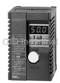


What they say about us
FANTASTIC RESOURCE
One of our top priorities is maintaining our business with precision, and we are constantly looking for affiliates that can help us achieve our goal. With the aid of GID Industrial, our obsolete product management has never been more efficient. They have been a great resource to our company, and have quickly become a go-to supplier on our list!
Bucher Emhart Glass
EXCELLENT SERVICE
With our strict fundamentals and high expectations, we were surprised when we came across GID Industrial and their competitive pricing. When we approached them with our issue, they were incredibly confident in being able to provide us with a seamless solution at the best price for us. GID Industrial quickly understood our needs and provided us with excellent service, as well as fully tested product to ensure what we received would be the right fit for our company.
Fuji
HARD TO FIND A BETTER PROVIDER
Our company provides services to aid in the manufacture of technological products, such as semiconductors and flat panel displays, and often searching for distributors of obsolete product we require can waste time and money. Finding GID Industrial proved to be a great asset to our company, with cost effective solutions and superior knowledge on all of their materials, it’d be hard to find a better provider of obsolete or hard to find products.
Applied Materials
CONSISTENTLY DELIVERS QUALITY SOLUTIONS
Over the years, the equipment used in our company becomes discontinued, but they’re still of great use to us and our customers. Once these products are no longer available through the manufacturer, finding a reliable, quick supplier is a necessity, and luckily for us, GID Industrial has provided the most trustworthy, quality solutions to our obsolete component needs.
Nidec Vamco
TERRIFIC RESOURCE
This company has been a terrific help to us (I work for Trican Well Service) in sourcing the Micron Ram Memory we needed for our Siemens computers. Great service! And great pricing! I know when the product is shipping and when it will arrive, all the way through the ordering process.
Trican Well Service
GO TO SOURCE
When I can't find an obsolete part, I first call GID and they'll come up with my parts every time. Great customer service and follow up as well. Scott emails me from time to time to touch base and see if we're having trouble finding something.....which is often with our 25 yr old equipment.
ConAgra Foods