

 Manufacturers
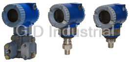
FOXBORO Electronic Pressure Transmitter
Description
Foxboro I/A Series Electronic Pressure Transmitters with HART Communication Protocol for Absolute and Gauge Pressure Measurement
Part Number
Electronic Pressure Transmitter
Price
Request Quote
Manufacturer
FOXBORO
Lead Time
Request Quote
Category
PRODUCTS - E
Datasheet
Foxboro-IA-Series-Intelligent-Absolute-Gauge-Pressure-Transmiters-datasheet1-1286099481.pdf
1845 KiB

Extracted Text
PSS 2A-1C13 B Product Specifications ® I/A Series Electronic Pressure Transmitters with HART Communication Protocol for Absolute and Gauge Pressure Measurement IAP10/IGP10 TRANSMITTER IAP10/IGP10 STRUCTURE CODES TRANSMITTER 20-23, 30, 31, IAP20/IGP20 D1, D2, S3, S4, STRUCTURE CODES TRANSMITTER 52, 53, 60-63, SC, AND SD D5, D6, S5, S6, SH, AND SJ These Intelligent, two-wire transmitters provide precise, reliable, measurement of gauge or absolute pressure, and transmit a 4 to 20 mA output signal with a superimposed HART digital signal for remote configuration and monitoring. HIGH DEPENDABILITY Sensor wetted parts materials include Co-Ni-Cr, 316L ss, and Hastelloy; additionally, Monel, • Silicon strain gauge sensors successfully field- tantalum, and gold-plated 316L ss sensors proven in many thousands of installations. offered for the IAP20/IGP20. Simple, elegant sensor packaging with very few Complies with NAMUR NE 21 interference parts; achieves exceptionally high reliability. immunity requirement, and NAMUR 105 Aluminum housing has durable, corrosion- overrange and underrange annunciations. resistant epoxy finish; 316 ss housing also CE marked; complies with applicable EMC, available; both meet NEMA 4X and IEC IP66. ATEX, and PED European Union Directives. Remote configuration with HART; or locally via Complies with electromagnetic compatibility the optional LCD Indicator. requirements of European EMC Directive HART protocol allows multidrop topology. 89/336/EEC by conforming to following CENELEC and IEC Standards: EN 50081-2, Can be provided with numerous configurations EN 50082-2, EN 61326, and IEC 61000-4-2 of direct connect or remote mount seals. through 61000-4-6. The IAP10 and IGP10 are offered with integral Meet numerous requirements for hazardous process connections for sanitary, and pulp and locations. Versions available to meet Agency paper installations. Also, the IGP10 is offered for flameproof and zone requirements. high gauge pressure applications to 52, 105, or Numerous mounting bracket set options. Many 210 MPa (7500, 15 000, or 30 000 psi). other options and accessories offered. SIL-Certified HART transmitter offered as an Standard 5-year warranty. option. PSS 2A-1C13 B Page 2 ® I/A Series PRESSURE TRANSMITTER FAMILY Analog Output Version (-A Electronics): Provides a 4 to 20 mA analog output and includes a The I/A Series Electronic Pressure Transmitters are a ® standard LCD Indicator to provide transmitter complete family of d/p Cell , gauge, absolute, configuration directly from on-board pushbuttons. multirange, multivariable, and premium performance Refer to PSS 2A-1C13 C. transmitters, as well as transmitters with remote or direct connect pressure seals, all using field-proven Analog Output Version (-V Electronics): silicon strain gauge sensors and common topworks. A low power, low voltage transmitter that draws no more than 3 mA, and transmits a 1 to 5 V dc output MODULAR ELECTRONICS signal. As with the -A version, it includes a standard A common HART electronics module is used for all LCD Indicator. Refer to PSS 2A-1C13 D. I/A Series HART Pressure Transmitters. Also, because all configuration and calibration data is HART INTELLIGENT MODULE CONFIGURED FOR stored in the sensor, you can replace a HART module 4 TO 20 MA OUTPUT with another HART module without transmitter Measurements and diagnostics are available from the reconfiguration or recalibration. HART Communicator connected to the two-wire loop Furthermore, if your needs change, the transmitter carrying the 4 to 20 mA measurement signal by using modular design allows easy migration to other a bidirectional digital signal superimposed on the 4 to standards, including FoxCom™, FOUNDATION 20 mA current signal. Fieldbus, and Analog 4 to 20 mA or 1 to 5 V dc. Multiple measurements are transmitted digitally, including not only the primary measurement in HART COMMUNICATION PROTOCOL pressure units, but also the electronics temperature VERSION -T ELECTRONICS and sensor temperature which can be used to 4 to 20 mA with HART communications. Allows direct monitor external heat tracing equipment. Complete analog connection to common receivers while still transmitter diagnostics are also communicated. providing full Intelligent Digital Communications using Configuration and reranging can be accomplished a HART Communicator or PC-based Configurator. with the Communicator, PC-based Configurator, or HART Communicators can be upgraded with software LCD Digital Indicator (with pushbuttons) option. to accommodate these transmitters. Also, Invensys HIGH PERFORMANCE Process Systems will make use of the HART Foundation library of registered DDs (Device Both direct-connected and bracket-mounted Descriptors), and reload a Communicator if the user transmitters utilize microprocessor-based correction desires to keep another supplier's DD along with the to achieve both excellent accuracy and ambient Foxboro DD. temperature compensation. In addition to HART Protocol, Foxboro also offers OPTIONAL SIL TRANSMITTERS other Transmitters with... Modern industrial processes tend to be technically complex and have the potential to inflict serious harm FoxCom Version, Software Configurable for Digital or to persons or property during a mishap. The IEC 4 to 20 mA Output (-D Electronics): 61508 standard defines safety as “freedom from Provides measurement integration with an I/A Series unacceptable risk.” SIL pressure transmitters with system, or allows direct analog connection to HART communication protocol, in conjunction with common receivers while still providing full Intelligent Triconex Safety Systems, provide integrated solutions Transmitter digital communication with a PC-based for safety and critical control applications. The configurator. Refer to PSS 2A-1C13 A. integrated solution is certified as interference-free from the 4 to 20 mA loop; this guarantees the integrity FOUNDATION Fieldbus Version (-F Electronics): of the safety system and the safety of the controlled This is a FISCO/FNICO compliant all digital, serial, process. The integrated design allows uninterrupted two-way communication system which interconnects operation of the safety function, while allowing access field devices such as transmitters, actuators, and to device level information via HART commands. The controllers. It is a local area network (LAN) with built- solution permits interface of device diagnostics with in capability to distribute control across the network. asset management systems without compromising Refer to PSS 2A-1C13 E. functional safety. Select Option -S2 for a SIL-certified HART Transmitter. A copy of the certification is available via Auxiliary Specification (AS) Code CERT-L. PSS 2A-1C13 B Page 3 MULTIDROP COMMUNICATIONS EASE OF INSTALLATION Point-to-point or multidrop topologies are permitted. Rotatable Topworks allows transmitter installation in Multidropping is the connection of several transmitters tight places, allows indicator to be positioned in to a single communications line. Communications preferred direction, and eases field retrofit. between the host computer and transmitters takes Two Conduit Entrances offer a choice of entry place digitally with the analog output of the transmitter positions for ease of installation and self-draining of fixed. Up to fifteen transmitters can be connected on condensation regardless of mounting position and a single twisted pair of wires or over leased telephone topworks rotation. lines. See Figures 8 and 9. Wiring Guides and Terminations provide ease of wire CHOOSE MOUNTING CONFIGURATION NEEDED entry and support, plenty of space to work and store excess wire, and large, rugged screw terminals for Direct Connected Transmitter (IAP10 and IGP10) easy wire termination. Light weight and easy-to-install. Uses 316L ss or OPTIONAL LCD DIGITAL INDICATOR Hastelloy C process connections, and a choice of A two-line digital indicator with on-board pushbuttons either 316L ss, Cobalt-Nickel-Chrome, or Hastelloy C displays the measurement with a choice of units. The for the sensing diaphragm. See Direct-Connected pushbuttons allow zero and span adjustments, as well Transmitters section. as local configuration without the need for a Bracket-Mounted Transmitter (IAP20 and IGP20) Communicator or PC-based Configurator. See Figure 10. A large selection of corrosion resistant process covers and sensing diaphragm materials; suitable for applications requiring low spans, vacuum service, and high overrange pressure. See Bracket-Mounted Transmitters section. PSS 2A-1C13 B Page 4 DIRECT CONNECTED TRANSMITTERS — IAP10 and IGP10 (Figure 1) EXCEPTIONAL VALUE The combination of small size, light weight, direct mounting, standard materials, and wide measurement capability with high performance make this an exceptionally cost effective solution for process pressure measurement. DIRECT PROCESS MOUNTING Because of their light weight and external threaded connection, these transmitters can be installed directly on process piping without mounting brackets. However, for unique requirements, an optional bracket is offered and connection can be made to the standard 1/4 NPT internal thread. Figure 1. Direct Connected Transmitter WIDE RANGEABILITY (Flameproof Version Shown on Left) Three absolute pressure versions are offered to allow HIGH GAUGE PRESSURE VERSIONS spans from 7 to 21 000 kPa (1 to 3000 psi), and four gauge pressure versions are offered to allow spans Three high gauge pressure versions with URLs of 52, from 7 to 42 000 kPa (1 to 6000 psi). Refer to IGP20 105, and 210 MPa (7500, 15 000, and 30 000 psi) are Transmitter for gauge pressure vacuum service. available in the IGP10 line. See PSS 2A-1C13 F. 316L ss, HASTELLOY C, AND Co-Ni-Cr PROCESS SANITARY AND PULP AND PAPER VERSIONS WETTED PARTS These transmitters are also available with integral With process connection of 316L ss or Hastelloy C, process connections for use in sanitary, and pulp and and sensor diaphragm available in either 316L ss, paper installations. See PSS 2A-1C13 K and Hastelloy C, or highly corrosion resistant Co-Ni-Cr, PSS 2A-1C13 L, respectively. this transmitter is an excellent choice for the vast majority of process pressure measurements. FLAMEPROOF DESIGN The IAP10 and IGP10 flameproof versions are designed to meet Agency flameproof and zone requirements. PSS 2A-1C13 B Page 5 BRACKET-MOUNTED TRANSMITTER — IAP20 AND IGP20 (Figure 2) SENSOR CORROSION PROTECTION FLAMEPROOF DESIGN Choice of 316L ss, Co-Ni-Cr, Hastelloy C, Monel, The transmitters are designed to meet Agency Gold-Plated 316L ss, and Tantalum materials. High flameproof and zone requirements. corrosion resistance of Co-Ni-Cr (TI 037-078) means long service life in many difficult applications without the extra cost for exotic materials. Also see TI 37-75b for process applicability with Co-Ni-Cr and other process wetted parts materials. WIDE RANGEABILITY REMOVABLE Gauge pressure measurement spans may be as low GASKETED as 0.12 kPa (0.5 inH O) to as high as 35 MPa 2 PROCESS (5000 psi) by choosing one of only six sensors, and CONNECTOR absolute pressure measurement spans may be as low as 0.87 kPa (3.5 inH O) to as high as 21 MPa 2 (3000 psi) by choosing one of only four sensors. This provides exceptional measurement range capability with a minimum of versions. VACUUM SERVICE Figure 2. Bracket-Mounted Transmitter Shown with A lower range limit of -100 kPa (-14.7 psi, -1 bar or 2 Conventional Process Connector kg/cm ) means that vacuum measurements are easily handled with the versatile IGP20 Gauge Pressure transmitter. PROCESS CONNECTOR SENSOR ASSEMBLY Removable, gasketed process connector (Figure 2) VITON O-RING allows a wide range of selections, including 1/4 NPT, PROCESS 1/2 NPT, Rc 1/4, Rc 1/2, and weld neck connections. INLET For highly corrosive chemical processes, a 1/2 NPT pvdf (Kynar) insert, as shown in Figure 3, is installed in the HI-side 316 ss cover and is used as the 1/2 NPT pvdf INSERT USED AS PROCESS CONNECTION process connector. In these applications, tantalum is used as the sensor diaphragm material. HI-SIDE COVER NORMALLY ACCEPTS CONVENTIONAL PROCESS CONNECTOR EASE OF MOUNTING TWO-VALVE MANIFOLD Figure 3. Bracket-Mounted Transmitter Shown with Optional two-valve manifold to isolate transmitter, and 1/2 NPT pvdf Insert Installed in HI-Side Cover vent pressure, is easily mounted directly to transmitter. PRESSURE SEALS Pressure seals are used with the IAP10, IGP10, Tables 1 and 2 list the various seals that can be used IAP20, and IGP20 Series Transmitters when it is with these transmitters. To order a transmitter with necessary to keep the transmitter isolated from the seals, both a Transmitter Model Number and Seal process. A sealed system is used for a process fluid Model Number are required. See PSS 2A-1Z11 A for that may be corrosive, viscous, subject to temperature a complete listing of pressure seal models and extremes, toxic, sanitary, or tend to collect and specifications. Also see Figure 4 for typical pressure solidify. seal configurations. PSS 2A-1C13 B Page 6 Table 1. Pressure Seals Used with IAP10, IGP10, IAP20, and IGP20 Transmitters Direct Connect Pressure Seal Assemblies Seal Model Seal Description Process Connections PSFLT Flanged, Direct Connect (Flanged Level), Flush ANSI Class 150/300/600 flanges and or Extended Diaphragm BS/DIN PN 10/40, 10/16, 25/40 flanges PSFAD Flanged, Direct Connect, Recessed Diaphragm ANSI CLass 150, 300, 600, 1500 flanges PSTAD Threaded, Direct Connect, Recessed Diaphragm 1/4, 1/2, 3/4, 1, or 1 1/2 NPT internal thread PSISD In-Line Saddle Weld, Direct Connect, Recessed Lower housing of seal is in-line saddle welded Diaphragm to nominal 3- or 4-inch (and larger) Pipe PSSCT Sanitary, Direct Connect (Level Seal), Flush Process Connection to Sanitary Piping with Diaphragm 2- or 3-inch Tri-Clamp PSSST Sanitary, Direct Connect (Level Seal), Extended Process Connection to 2-in Mini Spud or 4-in Diaphragm Standard Spud; Tri-Clamp Remote Mount, Capillary-Connected Pressure Seal Assemblies Seal Model Seal Description Process Connections PSFPS Flanged, Remote Mount, Flush Diaphragm ANSI Class 150/300/600 flanges and BS/DIN PN 10/40 flanges PSFES Flanged, Remote Mount, Extended Diaphragm ANSI Class 150/300/600 flanges and BS/DIN PN 10/40, 10/16, 25/40 flanges PSFAR Flanged, Remote Mount, Recessed Diaphragm ANSI Class 150/300/600/1500 flanges PSTAR Threaded, Remote Mount, Recessed Diaphragm 1/4, 1/2, 3/4, 1, or 1 1/2 NPT internal thread PSISR In-Line Saddle Weld, Remote Mount, Recessed Lower housing of seal is in-line saddle welded Diaphragm to nominal 3- or 4-inch (and larger) Pipe PSSCR Sanitary, Remote Mount, Flush Diaphragm Process Connection secured with a Tri-Clamp to a 2- or 3-inch pipe PSSSR Sanitary, Remote Mount, Extended Diaphragm Process Connection to 2-in Mini Spud or 4-in Standard Spud; Tri-Clamp Table 2. I/A Series Pressure Transmitters and Applicable Pressure Seals Used with Pressure Seal Model: (a) Transmitter Model FLT FAD TAD ISD SCT SST FPS FES FAR TAR ISR SCR SSR IAP10 – – – IGP10 – – – IAP20 – – – – – – IGP20 – – – (a) Pressure Seal models are shown with an abbreviated code; all seal codes have a PS prefix; for example, FLT is really PSFLT. Figure 4. Typical Pressure Seals used with IAP10, IGP10, IAP20, and IGP20 Transmitters PSS 2A-1C13 B Page 7 FUNCTIONAL SPECIFICATIONS Span and Range Limits for IAP10 and IGP10 Transmitters Span Limits Range Limits (Absolute or Gauge Units) Span 2 2 Code MPa psi bar or kg/cm MPa psi bar or kg/cm C 0.007 and 0.21 1 and 30 0.07 and 2.1 0 and 0.21 0 and 30 0 and 2.1 D 0.07 and 2.1 10 and 300 0.7 and 21 0 and 2.1 0 and 300 0 and 21 E 0.7 and 21 100 and 3000 7 and 210 0 and 21 0 and 3000 0 and 210 F (a) 14 and 42 2000 and 6000 140 and 420 0 and 42 0 and 6000 0 and 420 (a) Span Limit Code F is applicable to IGP10 Transmitter only. Maximum Overrange and Proof Pressure Ratings for IAP10 and IGP10 Transmitters Maximum Overrange Pressure Rating (a) Proof Pressure Rating (a)(b) Span 2 2 Code MPa psi bar or kg/cm MPa psi bar or kg/cm C 0.31 45 3.15 0.827 120 8.27 D 3.1 450 31.5 8.27 1200 82.7 E 31 4500 315 79.3 11500 793 F (c) 59 8400 588 152 22000 1517 (a) Values listed are in absolute or gauge pressure units, as applicable. Maximum overrange pressure is the maximum pressure that may be applied without causing damage to the transmitter. (b) Proof pressure ratings meet ANSI/ISA Standard S82.03-1988. Unit may become nonfunctional after application of proof pressure. (c) Span Limit Code F is applicable to IGP10 Transmitter only. Span and Range Limits for IAP20 and IGP20 Transmitters Span Limits Range Limits (Absolute or Gauge Units) (a) Span Code kPa inHOmbar kPa inHOmbar 2 2 A (b) 0.12 and 7.5 0.5 and 30 1.2 and 75 -7.5 and +7.5 -30 and +30 -75 and +75 B 0.87(c) and 50 3.5(c) and 200 8.7(c) and 500 -50(a) and +50 -200(a) and +200 -500(a) and +500 2 2 MPa psi bar or kg/cm MPa psi bar or kg/cm C 0.007 and 0.21 1 and 30 0.07 and 2.1 -0.1(a) and 0.21 -14.7(a) and +30 -1(a) and +2.1 D 0.07 and 2.1 10 and 300 0.7 and 21 -0.1(a) and 2.1 -14.7(a) and +300 -1(a) and +21 E (d) 0.7 and 21 100 and 3000 7 and 210 -0.1(a) and 21 -14.7(a) and +3000 -1(a) and +210 F (b) 1.38 and 35 200 and 5000 13.8 and 350 -0.1 and +35 -14.7 and +5000 -1 and +350 (a) For absolute pressure transmitters (IAP20), the lower range limit is 0. (b) Span Codes A and F applicable to IGP20 Transmitter only. Also, Span Code A is not available when pressure seals are specified. (c) For IAP20, the minimum span for factory calibration is 1.2 kPa (5 inH O, 12.4 mbar). Can be field reranged within limits shown in table. 2 (d) When certain options are specified, the upper span and range limit values are reduced as shown in the “Options Impact” table. Maximum Overrange and Proof Pressure Ratings for IAP 20 and IGP20 Transmitters (a) Overrange Pressure Rating Proof Pressure Rating (b) Transmitter Configuration bar or bar or 2 2 (See Model Code for Description of Options) MPa psi kg/cm MPa psi kg/cm Standard with IGP20 Span Code F only 51.8 7500 518 100 14500 1000 Standard (c) or with Option -B2, -D3, or -D7 25 3625 250 100 14500 1000 With Option -B3 20 2900 200 70 11150 700 With Option -D1 16 2320 160 64 9280 640 With Option -B1 or -D5 15 2175 150 60 8700 600 With Option -D2, -D4, -D6, or -D8 10 1500 100 40 6000 400 With Structure Codes 78 and 79 (pvdf insert) 2.1 300 21 8.4 1200 84 (a) Refer to Model Code section for application and restrictions related to the items listed in the table. (b) Proof pressure ratings meet ANSI/ISA Standard S82.03-1988. Unit may become nonfunctional after application of proof pressure. (c) Standard with IAP20/IGP20 Span Codes A to E. PSS 2A-1C13 B Page 8 FUNCTIONAL SPECIFICATIONS (Cont.) Impact of Certain Options on IAP20/IGP20 Span and Range Limits (a) Option Description (Also see Model Code) Span and Range Limits Derated to: 2 -B3 B7M Bolts and Nuts (NACE) 20 MPa (2900 psi, 200 bar, or kg/cm ) 2 -D1 DIN Construction 16 MPa (2320 psi, 160 bar or kg/cm ) 2 -D5 or -B1 DIN Construction or 316 ss Bolting 15 MPa (2175 psi, 150 bar or kg/cm ) 2 -D2, -D4, -D6, or -D8 (a) DIN Construction (a) 10 MPa (1500 psi, 100 bar or kg/cm ) (a) (a) Refer to Model Code section for application and restrictions related to the items listed in the table. Output Signal and Configuration Adjustable Damping Output is 4 to 20 mA with digital HART The transmitter response time is normally 0.75 s, or communications. For multidrop applications, the mA the electronically adjustable setting of 0.00 (none), signal is fixed at 4 mA to provide power to the 0.25, 0.50, 1, 2, 4, 8, 16, or 32 seconds, whichever is device. Configurable using the HART greater, for a 90% recovery from an 80% input step Communicator, PC-based Configurator, or optional as defined in ANSI/ISA S51.1. (For 63.2% recovery, LCD Indicator with on-board pushbuttons. 0.50 s with sensors B to F, and 0.60 s with sensor A.) Electronics and Sensor Temperatures Minimum Allowable Absolute Pressure vs. Readable from the Communicator or PC-based Transmitter Temperature Configurator. Measurement is transmitter WITH SILICONE FILL FLUID temperature, at the sensor and the electronic Full vacuum: up to 121°C (250°F) module, not necessarily process temperature. WITH FLUORINERT FILL FLUID Refer to Figure 6. Field Wiring Reversal TEMPERATURE, ° C No transmitter damage. -30 0 30 60 40 120 140 Supply Voltage Requirements and External Loop 120 Load Limitations (Figure 5) 100 Nominal minimum supply voltage is 11.5 V dc. This FLUORINERT value can be reduced to 11 V dc by using a plug-in 80 FC-43 FLUID jumper across the test receptacles in the field wiring OPERATING 60 AREA compartment terminal block as shown in the 40 Physical Specifications section. 20 0 1500 TYPICAL SUPPLY 1450 -25 0 50 100 150 200 250 VOLTAGE AND TEMPERATURE, ° F LOAD LIMITS V dc LOAD Ω Figure 6. Minimum Allowable 24 250 & 594 Absolute Pressure vs. Transmitter Temperature, 30 250 & 880 1000 32 250 & 975 Fluorinert FC-43, 2.6 cSt at 25°C (77°F) MIN. LOAD WITH Write Protect Jumper COMMUNICATOR Can be positioned to lock out all configurators from OR PC-BASED 500 making transmitter database changes. This makes CONFIG. OPERATING transmitter suitable for Safety Shutdown System AREA 250 Applications that require this feature. SEE NOTE BELOW Suppressed Zero and Elevated Zero 0 Suppressed or elevated zero ranges are acceptable 0 10 20 30 40 50 as long as the Span and Range Limits are not 11.5 42 exceeded (elevated zero applicable to IGP20 only). SUPPLY VOLTAGE, V dc NOTE Zero and Span Adjustments Transmitter will function with an output load less Zero and span adjustments can be initiated using than 250 Ω provided that a HART Communicator or PC-based Configurator is not connected to it. the Communicator, a PC-based Configurator, or the Use of a Communicator or PC-based Configurator optional LCD with on-board pushbuttons. requires 250 Ω minimum load. Figure 5. 4 to 20 mA Output, Supply Voltage vs. Output Load OUTPUT LOAD, Ω ABSOLUTE PRESSURE, mmHg PSS 2A-1C13 B Page 9 FUNCTIONAL SPECIFICATIONS (Cont.) Zeroing for Nonzero-Based Ranges removed by a mA trim without application of Dual Function Zeroing allows zeroing with the pressure. Changing module types (e.g., from one to transmitter open to atmosphere, even when there is another communication protocol) may require a nonzero-based range. This greatly simplifies reconfiguration and recalibration, as well as a position effect zeroing on many pressure and level different terminal block, but all factory applications. It applies to the LCD Indicator characterization data is retained. pushbuttons and optional External Zero Adjustment. Configuration Capability Current Outputs for Overrange, Fail, and Offline CALIBRATED RANGE Conditions – Input range within Range Limits Offline Configurable between 4 and 20 mA – One of the pressure units shown in Table 3 Sensor Failure Configurable to Fail LO or Fail HI OUTPUT MEASUREMENT #1 – Fail LO 3.60 mA DIGITAL PRIMARY VARIABLE AND 4 TO 20 mA Underrange 3.80 mA Mode: Linear Overrange 20.50 mA Units: One of the pressure units shown in Table 3 Fail HI 21.00 mA OUTPUT MEASUREMENT #2 – DIGITAL SECONDARY VARIABLE Configuration and Calibration Data and Mode: Linear Electronics Upgradeability Units: One of the pressure units shown in Table 3 All factory characterization data and user configuration and calibration data are stored in the Table 3. Allowable Pressure Units sensor (refer to Figure 7, Transmitter Functional for Calibrated Range (a) Diagram). This means that the electronics module 2 may be replaced, with one of like type, without the inH O psi Pa atm g/cm 2 2 need for reconfiguration or recalibration. ftH O inHg kPa bar kg/cm 2 mmH O mmHg MPa mbar torr 2 Although module replacement can affect accuracy mH O – – – – 2 by a maximum of 0.20% of span, this error can be (a) The suffix (a) is added to the unit to indicate absolute pressure; e.g., psia. Sensor Electronics Module Digital to Analog to Digital Analog Converter 4 to 20 mA Converter Output with HART Nonvolatile Microprocessor Communications Memory - Sensor Linearization - Complete - Reranging Transmitter - Loop Calibration Configuration - Damping Correction - - Engineering Units - Coefficients Diagnostic Routines - - Calibration Failsafe High or Low - Digital Communication Data - Temp. Compensation HART Pressure Sensor Sensor Modem D/A Converter Temperature 1200 Baud Remote Measurement Communication Piezo-Resistive Sensor Memory HART - Calibration Communicator Measured - Configuration or Pressure Nonvolatile Mem. PC-based - Program Configurator Atmospheric - Module Coeff. Vent (Gauge), or Sealed LCD Indicator/Configurator External Zero Reference including Zero and Span Adjustment (Absolute) Figure 7. Transmitter Functional Block Diagram Pressure Measurement PSS 2A-1C13 B Page 10 FUNCTIONAL SPECIFICATIONS (Cont.) Communications Configurable for either Analog Mode (4 to 20 mA) or 250 Ω MINIMUM BETWEEN POWER Multidrop Mode (fixed current). Digital SUPPLY AND COMMUNICATOR communications is provided in both modes based + upon the FSK (Frequency Shift Keying) technique + INDICATOR which alternately superimposes one of two different POWER + frequencies on the uninterrupted current carried by SUPPLY the two signal/power wires. See Figures 8 and 9. ANALOG MODE (4 to 20 mA) The analog 4 to 20 mA output signal is updated 30 times per second. Digital communications + between the transmitter and HART Communicator is rated for distances up to 3050 m (10 000 ft). The COMMUNICATOR OR PC- DIRECT CONTROLLER digital communications rate is 1200 baud and BASED CONFIGURATOR CONNECTED OR MAY BE CONNECTED AT requires a minimum loop load of 250 ohms. TRANSMITTER RECORDER ANY POINT IN THE LOOP, SHOWN MULTIDROP MODE (FIXED CURRENT) SUBJECT TO THE 250 Ω This Mode supports communications with up to 15 REQUIREMENT SHOWN. transmitters on a single pair of signal/power wires. Figure 8. The output signal is updated 4 times/second and 4 to 20 mA Output Functional Block Diagram carries not only the pressure measurement, but Point-to-Point Communications also the sensor and electronics temperatures (internal recalculation rate for temperature is once per second). Communication between transmitter and system, or between transmitter and HART HART HOST COMPATIBLE Communicator or PC-based Configurator, is rated COMPUTER MODEM 250 for distances up to 1525 m (5000 ft). The digital MIN. communications rate is 1200 baud and requires a minimum loop load of 250 ohms. Remote Communications The HART Communicator or PC-based Configurator has full access to all of the “Display” and “Display GAUGE TEMP. d/p Cell POWER PRESS and Reconfigure” items listed below. It may be XMTR XMTR SUPPLY XMTR connected to the communications wiring loop, and does not disturb the mA current signal. Plug-in Figure 9. connection points for the communicator are also Typical Multidrop Functional Block Diagram provided on the transmitter terminal block. (Up to Fifteen Transmitters) “Display” Items Process Measurement in two formats Electronics and Sensor Temperatures mA Output “Display and Reconfigure” Items Two Digital Outputs for Pressure Choice of Pressure Engineering Units Reranging without Pressure Zero and Span Calibration Electronic Damping Temperature Sensor Failure Strategy Failsafe Direction Tag, Descriptor, and Message Date of Last Calibration PSS 2A-1C13 B Page 11 FUNCTIONAL SPECIFICATIONS (Cont.) Optional LCD Indicator w/Pushbuttons (Figure 10) Optional External Zero Adjustment Indicator provides: An external pushbutton mechanism (Figure 10) is Two Lines: Five numeric characters on top line isolated from the electronics compartment and (four when a minus sign is needed); and seven magnetically activates an internal reed switch alphanumeric characters on bottom line. through the housing. This eliminates a potential leak path for moisture or contaminants to get into the Measurement readout: Value displayed on top electronics compartment. This zero adjustment can line, and units label displayed on bottom line. be disabled by a configuration adjustment. Configuration and calibration prompts. Optional Custom Configuration (Option -C2) Pushbuttons (two) provide the following For the transmitter to be custom configured by the configuration and calibration prompts: factory, the user must fill out a data form. If this Zero and Span settings, noninteractive to option is not selected, a standard (default) automatically set output to either 4 mA or 20 mA configuration will be provided; for example: using the “NEXT” and “ENTER” pushbuttons. Example of 4 and 20 mA Jog Settings, allowing the user to Standard Custom easily increment the mA output signal up or down (Default) Configuration in fine steps to match a value shown on an Parameter Configuration Option -C2 external calibrator. Tagging Info. Forward or Reverse Output Tag TAG PT101 Damping Adjustment (8 char. max.) TAG NAME WATER PRESS. Descriptor Enable/Disable Optional External Zero (16 char. max.) Temperature Sensor Failure Strategy LOCATION BUILDING 2 Message Failsafe Action (High or Low) (32 char. max.) 0 0 (a) HART Poll Address Units Label (Bottom Line of Display) (0 to 15) Settable Lower and Upper Range Values for Calibrated Range Transmission and Display (Top Line) Pressure EGU per S.O. (b) inH O 2 Reranging without Pressure LRV per S.O. (c) 0 URV per S.O. (c) 100 Percent (%) Output Measurement #1 Pressure EGU per S.O. (d) inH O 2 Output 4 to 20 mA 4 to 20 mA (e) TOPWORKS WITH COVER Measurement #2 REMOVED Pressure EGU per S.O. (d) inH O 2 Other Electronic Damping None 0.5 s OPTIONAL Failsafe Direction Upscale Downscale EXTERNAL OPTIONAL Failure Strategy Continue Failsafe ZERO LCD Ext. Zero Option Enabled Disabled PUSHBUTTON INDICATOR (a) Address is 1 to 15 for multidrop applications. "ENTER" "NEXT" (b) Units from Table 3. If not specified, factory default calibration is PUSHBUTTON PUSHBUTTON zero to maximum span; default units vary by sensor code. (c) Within Span and Range Limits for selected sensor code. Figure 10. LCD Indicator with Pushbuttons (d) Same as Calibrated Range. (e) Fixed current is used for multidrop applications. Any of the configurable parameters in the table above can easily be changed using the HART Communicator or PC-based Configurator. NEXT ENTER PSS 2A-1C13 B Page 12 OPERATING, STORAGE, AND TRANSPORTATION CONDITIONS Reference Storage and Operating Normal Operating Transportation Influence Conditions Conditions (a) Operative Limits (a) Limits Process Connection Temp. with Silicone Fill Fluid 24 ±2°C -29 to + 82°C -46 and +121°C(b) Not Applicable (75 ±3°F) (-20 to +180°F) (-50 and +250°F)(b) with Fluorinert Fill Fluid 24 ±2°C -29 to + 82°C -29 and +121°C Not Applicable (75 ±3°F) (-20 to +180°F) (-20 and +250°F) Electronics Temperature 24 ±2°C -29 to + 82°C(g) -40 and +85°C(g) -54 and +85°C (75 ±3°F) (-20 to +180°F)(g) (-40 and +185°F)(g) (-65 and +185°F) with LCD Indicator (c) 24 ±2°C -20 to + 82°C(g) -29 and +85°C(g) -54 and +85°C (75 ±3°F) (-4 to +180°F)(g) (-20 and +185°F)(g) (-65 and +185°F) Relative Humidity (d) 50 ±10% 0 to 100% 0 and 100% 0 and 100% Noncondensing Supply Voltage - mA Output 30 ±0.5 V dc 11.5 to 42 V dc (e) 11.5 and 42 V dc (e) Not Applicable Output Load - mA Output 650 Ω 0 to 1450 Ω 0 and 1450 Ω Not Applicable 2 2 Vibration 1 m/s 6.3 mm (0.25 in) Double Amplitude: 11 m/s (0.1 “g”) from 5 to 15 Hz with Aluminum Housing and (1.1 “g”) from 5 to 9 Hz with 316 ss Housing from 2.5 to 5 Hz - - - - - - - - - - - - - - - - - - - - - - - - - - - - - - - (in Shipping 2 0 to 30 m/s (0 to 3 “g”) from 15 to 500 Hz Package) with Aluminum Housing; and 2 0 to 10 m/s (0 to 1 “g”) from 9 to 500 Hz with 316 ss Housing Mounting Position Upright (f) Upright (f) No Limit Not Applicable (a) Temperature limits are derated as follows: IAP20 and IGP20 Transmitters: to -7 and +82°C (20 and 180°F) when Structure Codes 78/79 (pvdf inserts) are used, and to 0 and 60°C (32 and 140°F) when DIN Construction Options D2/D4/D6/D8 are used. (b) Selection of Option -J extends the low temperature limit of transmitters with silicone filled sensors down to -50°C (-58°F). (c) Although the LCD will not be damaged at any temperature within the “Storage and Transportation Limits”, updates will be slowed and readability decreased at temperatures outside the “Normal Operating Conditions”. (d) With topworks covers on and conduit entrances sealed. (e) 11.5 V dc can be reduced to 11 V dc by using a plug-in shorting bar; see “Physical Specifications” sections. (f) Sensor process wetted diaphragms in a vertical plane for IAP20 and IGP20 Transmitter. (g) Refer to the Electrical Safety Specifications section for a restriction in ambient temperature limits with certain electrical approvals/certifications. PSS 2A-1C13 B Page 13 PERFORMANCE SPECIFICATIONS Zero-Based Calibrations; 316L ss or Co-Ni-Cr Diaphragms with Silicone Fluid for IGP10 and IAP10; Cobalt-Nickel-Chromium or 316L Stainless Steel Sensor with Silicone Fluid for IGP20; Under Reference Operating Conditions unless otherwise Specified; URL = Upper Range Limit, and Span = Calibrated Span. Accuracy (Includes Linearity, Hysteresis, RFI Effect and Repeatability) The output error is less than 0.1% of span for radio Accuracy, % of Span (a)(b) frequencies in the range of 27 to 1000 MHz and field intensity of 30 V/m when the transmitter is properly Spans ≥10% URL Spans <10% URL installed with shielded conduit and grounding, and ±0.060% ±[0.025 + 0.0035 (URL/Span)]% housing covers are in place. (Per IEC Std. 61000-4-3.) (a) Add ±0.04% for Span Code A, and ±0.02% for Span Codes E and F. Position Effect (b) Subtract ±0.01% for digital output accuracy. The transmitter may be mounted in any position. Any zero effect caused by the mounting position can be Stability eliminated by rezeroing. There is no span effect. Long term drift is less than ±0.05% of URL per year over a 5-year period. Switching and Indirect Lightning Transients The transmitter can withstand a transient surge up to Calibration Frequency 2000 V common mode or 1000 V normal mode The calibration frequency is five years. The five without permanent damage. The output shift is less years is derived using the values of allowable error than 1.0%. (Per ANSI/IEEE C62.41-1980 and (% span), TPE (% span), performance margin IEC Std. 61000-4-5.) (% span), and stability (% span/month); where: Ambient Temperature Effect Performance Margin Total effect for a 28°C (50°F) change within Normal Calibration Frequency == ------- ----------------- ----------------- ------------- Months Stability Operating Condition limits is: Power-Up Time For the IAP10 and IGP10 Transmitters Less than 5 seconds for output to reach first valid Span Code (a) Ambient Temperature Effect measurement. C, D, E, and F ±(0.03% URL + 0.060% Span) (a) Span Code F applicable to IGP10 Transmitter only. Supply Voltage Effect The output changes less than 0.005% of span for For the IAP20 and IGP20 Transmitters each 1 V change within the specified supply voltage Span Code Ambient Temperature Effect requirements. See Figure 5. A (a) ±(0.18% URL + 0.025% Span) Vibration Effect B and C ±(0.03% URL + 0.060% Span) Total effect is ±0.2% of URL per “g” for vibrations in D ±(0.05% URL + 0.045% Span) the frequency range of 5 to 500 Hz; with double E and F (a) ±(0.08% URL + 0.025% Span) amplitudes of 6.3 mm (0.25 in) in the range of 5 to (a) Span Codes A and F applicable to IGP20 Transmitter only. 15 Hz, or accelerations of 3 “g” in the range of 15 to 500 Hz, whichever is smaller, for transmitters with NOTE aluminum housings; and with double amplitudes of For additional ambient temperature effect 6.3 mm (0.25 in) in the range of 5 to 9 Hz, or when pressure seals are used, see accelerations of 1 “g” in the range of 9 to 500 Hz, PSS 2A-1Z11 A. whichever is smaller, for transmitters with 316 ss housings. PSS 2A-1C13 B Page 14 PHYSICAL SPECIFICATIONS Direct Connected Bracket Mounted Absolute and Gauge Pressure Absolute and Gauge Pressure Description Transmitters IAP10 and IGP10 Transmitters IAP20 and IGP20 Process Wetted Parts Mat'ls. (High Pressure Side) Process Connection 316L ss or Hastelloy C Carbon Steel, 316 ss, Hastelloy C, Monel, or pvdf (Kynar) Gaskets Not Applicable Glass Filled ptfe (Chemloy), Viton Sensor Diaphragm 316L ss, Co-Ni-Cr, Co-Ni-Cr, 316L ss, Gold-Plated or Hastelloy C 316L ss, Hastelloy C, Monel, or Tantalum Reference Side Mat’ls. IGP10 Transmitter: Sensor Diaphragm: (Atmospheric Pressure Side) Silicon, Pyrex, RTV, and 316 ss Same as specified for High Pressure IAP10 Transmitter: side process wetted material. N/A Cover: 316 ss Sensor Fill Fluid Silicone or Fluorinert Silicone or Fluorinert Bolts and Nuts for Process N/A Standard Bolting: Cover and Connector ASTM A193, Grade B7 Bolts ASTM A194, Grade 2H Nuts Optional Bolting: 316 ss, Type 17-4 ss, or B7M (NACE) Electrical Housing and Two compartments to separate electronics from field connections. Material is Housing Covers low copper (1% maximum) die-cast aluminum alloy with epoxy finish, or 316 ss. Environmental Protection Dusttight and weatherproof per IEC IP66 and NEMA 4X. Electronics Module Printed wiring assemblies are conformally coated for moisture and dust protection. Electrical Connections 1/2 NPT (Code 1) or PG 13.5 (Code 2) entrances on both sides of electronics housing, as specified. Unused entrance must be plugged to ensure moisture and RFI protection (Aluminum or 316 ss plug supplied by Foxboro). Mounting Position The transmitter may be mounted in any orientation. Approximate Mass Standard Transmitter With Process Connectors (Does not include seals. 1.5 kg (3.3 lb) 4.2 kg (9.2 lb) Refer to PSS 2A-1Z11 A for With 316 ss Housing Without Process Connectors integral transmitter and seal Add 1.1 kg (2.4 lb) 3.5 kg (7.8 lb) systems) With LCD Indicator Option With 316 ss Housing Add 0.2 kg (0.4 lb) Add 1.1 kg (2.4 lb) With LCD Indicator Option Add 0.2 kg (0.4 lb) Field Terminal Connections TERMINAL BLOCK LOCATED IN FIELD TERMINAL SIDE EARTH (GROUND) OF TRANSMITTER TERMINAL SCREW, OPTIONAL COMMUNICATOR 0.164-32 SHORTING BAR OR PC-BASED + (SB-11) REDUCES CONFIGURATOR (+) AND (-) MINIMUM VOLTAGE PLUGS INSERTED POWER HHT FROM 11.5 V dc HERE TERMINAL TO 11 V dc SCREWS, USED TO CHECK CAL+ 0.164-32 TRANSMITTER 4 TO 20 mA OUTPUT RECEPTACLES (3) - FOR STANDARD BANANA PLUGS PSS 2A-1C13 B Page 15 ELECTRICAL SAFETY SPECIFICATIONS IAP10 and IGP10 Transmitters Electrical Testing Laboratory, Types of Safety Protection, and Area Classification Application Conditions Design Code ATEX flameproof; II 2 GD EEx d IIC, Zone 1. Temperature Class T6, T85°C, D Ta = -40°C to +80°C. ATEX intrinsically safe; II 1 GD EEx ia IIC, Zone 0. Temperature Class T4, Ta = -40°C to +80°C. E ATEX protection n; II 3 GD, EEx nL IIC, Zone 2. Temperature Class T4, Ta = -40°C to +80°C. N ATEX multiple certifications, ia and ib, and n. Refer Applies to Codes E and N but not to Code D. M to ATEX Codes E and N for details. ATEX multiple certifications, ia and ib, d, and n. Applies to Codes D, E, and N. P Refer to ATEX Codes D, E, and N for details. CSA intrinsically safe for Class I, Division 1, Temperature Class T4A at 40°C and T3C at Groups A, B, C, and D, Class II, Division 1, 85°C maximum ambient. Groups E, F, and G; Class III, Division 1. Temperature Class T4 at 40°C and T3 at Also, zone certified intrinsically safe Ex ia IIC, and 85°C maximum ambient. energy limited Ex nA II. C CSA explosionproof for Class I, Division 1, Maximum Ambient Temperature 85°C. Groups B, C, and D, and dust-ignitionproof for Class II, Division 1, Groups E, F, and G; and Class III, Division 1. CSA Class I, Division 2, Groups A, B, C, and D; Temperature Class T4A at 40°C and T3C at Class II, Division 2, Groups F and G; and Class III, 85°C maximum ambient. Division 2. CSA field device zone certified flameproof Maximum Ambient Temperature 85°C. B Ex d IIC. Also, all certifications of Code C above. FM intrinsically safe for Class I, Division 1, Temperature Class T4A at 40°C and T4 at Groups A, B, C, and D, Class II, Division 1, 85°C maximum ambient. Groups E, F, and G; Class III, Division 1. Temperature Class T4 at 85°C maximum Also, zone certified intrinsically safe AEx ia IIC. ambient. FM explosionproof for Class I, Division 1, Temperature Class T6 at 80°C and T5 at F Groups B, C, and D; and dust-ignitionproof for 85°C maximum ambient. Class II, Division 1, Groups E, F, and G; and Class III, Division 1. FM nonincendive Class I, Division 2, Groups A, B, Temperature Class T4A at 40°C and T4 at C, and D; Class II, Division 2, Groups F and G, 85°C maximum ambient. and Class III, Division 2. FM field device zone certified flameproof Temperature Class T6 at 75°C maximum G AEx d IIC. Also, all certifications of Code F above. ambient. IECEx intrinsically safe, Ex ia IIC. Temperature Class T4, Ta = -40°C to +80°C. T IECEx protection n, Ex nL IIC. Temperature Class T4, Ta = -40°C to +80°C. U IECEx flameproof, Ex d IIC. Temperature Class T6, Ta = -40°C to +75°C. V NOTE 1. Transmitter has been designed to meet the electrical safety descriptions listed. Contact Invensys Process Systems for information or status of testing laboratory approvals or certifications. 2. See Model Code for availability of Electrical Safety Design Codes with particular Transmitter structures. 3. Refer to applicable Instruction Manual for application conditions and connectivity requirements. 4. When selecting ATEX Safety Design Code M or P, the user must permanently mark (check off in rectangle block on data plate) one type of protection only (ia and ib, d, or n). Do not change this mark. PSS 2A-1C13 B Page 16 ELECTRICAL SAFETY SPECIFICATIONS (Cont.) IAP20 and IGP20 Transmitters Electrical Testing Laboratory, Types of Safety Protection, and Area Classification Application Conditions Design Code ATEX flameproof; II 2 GD EEx d IIC, Zone 1. Temperature Class T6, T85°C, D Ta = -40°C to +80°C. ATEX intrinsically safe; II 1 GD EEx ia IIC, Zone 0. Temperature Class T4, Ta = -40°C to +80°C. E ATEX protection n; II 3 GD, EEx nL IIC, Zone 2. Temperature Class T4, Ta = -40°C to +80°C. N ATEX multiple certifications, ia and ib, and n. Refer Applies to Codes D, E, and N. M to ATEX Codes E and N for details. CSA intrinsically safe for Class I, Division 1, Temperature Class T4A at 40°C and T3C at Groups A, B, C, and D; Class II, Division 1, 85°C maximum ambient. Groups E, F, and G; Class III, Division 1. Temperature Class T4 at 40°C and T3 at Also, zone certified intrinsically safe Ex ia IIC, and 85°C maximum ambient. energy limited Ex nA II. C CSA explosionproof for Class I, Division 1, Maximum Ambient Temperature 85°C. Groups B, C, and D, and dust-ignitionproof for Class II, Division 1, Groups E, F, and G; and Class III, Division 1. CSA Class I, Division 2, Groups A, B, C, and D; Temperature Class T4A at 40°C and T3C at Class II, Division 2, Groups F and G; and Class III, 85°C maximum ambient. Division 2. CSA field device zone certified flameproof Maximum Ambient Temperature 85°C. B Ex d IIC. Also, all certifications of Code C above. FM intrinsically safe for Class I, Division 1, Temperature Class T4A at 40°C and T4 at Groups A, B, C, and D; Class II, Division 1, 85°C maximum ambient. Groups E, F, and G; Class III, Division 1. Temperature Class T4 at 85°C maximum Also, zone certified intrinsically safe AEx ia IIC. ambient. FM explosionproof for Class I, Division 1, Temperature Class T6 at 80°C and T5 at F Groups B, C, and D; and dust-ignitionproof for 85°C maximum ambient. Class II, Division 1, Groups E, F, and G, and Class III, Division 1. FM nonincendive Class I, Division 2, Groups A, B, Temperature Class T4A at 40°C and T4 at C, and D; Class II, Division 2, Groups F and G; 85°C maximum ambient. and Class III, Division 2. FM field device zone certified flameproof Temperature Class T6 at 75°C maximum G AEx d IIC. Also, all certifications of Code F above. ambient. IECEx intrinsically safe, Ex ia IIC. Temperature Class T4, Ta = -40°C to +80°C. T IECEx protection n, Ex nL IIC. Temperature Class T4, Ta = -40°C to +80°C. U IECEx flameproof, Ex d IIC. Applies to Version 5 electronic module. T6, Ta = 80°C; T5, Ta = 85°C V Ambient Temperature -20°C to +85°C. NOTE 1. Transmitter has been designed to meet the electrical safety descriptions listed. Contact Invensys Process Systems for information or status of testing laboratory approvals or certifications. 2. See Model Code for availability of Electrical Safety Design Codes with particular Transmitter structures. 3. Refer to applicable Instruction Manual for application conditions and connectivity requirements. 4. When selecting ATEX Safety Design Code M or P, the user must permanently mark (check off in rectangle block on data plate) one type of protection only (ia and ib, d, or n). Do not change this mark. PSS 2A-1C13 B Page 17 MODEL CODES IAP10 and IGP10 Transmitters Description Model I/A Series, Electronic, Direct Connected Absolute Pressure Transmitter IAP10 (a) I/A Series, Electronic, Direct Connected Gauge Pressure Transmitter IGP10 (a) Electronics Versions and Output Signal Intelligent; Digital HART and 4 to 20 mA dc (Version -T) -T Structure Code - Select from one of the following six groups: 1. Transmitter Only (no seals) Process Sensor Connection Sensor Fill Fluid Connection Type 316L ss Co-Ni-Cr Silicone 1/2 NPT External Thread, 1/4 NPT Internal Thread 20 316L ss Co-Ni-Cr Fluorinert 1/2 NPT External Thread, 1/4 NPT Internal Thread 21 316L ss 316L ss Silicone 1/2 NPT External Thread, 1/4 NPT Internal Thread 22 316L ss 316L ss Fluorinert 1/2 NPT External Thread, 1/4 NPT Internal Thread 23 316L ss Hastelloy C Silicone 1/2 NPT External Thread, 1/4 NPT Internal Thread 30 316L ss Hastelloy C Fluorinert 1/2 NPT External Thread, 1/4 NPT Internal Thread 31 2. Transmitter Prepared for Foxboro Model Coded Seals (b) Transmitter Prepared for Foxboro Direct Connect Seal; Silicone Fill in Sensor (c) D1 Transmitter Prepared for Foxboro Direct Connect Seal; Fluorinert Fill in Sensor (IGP10 only) (c) D2 Transmitter Prepared for Foxboro Remote Mount Seal; Silicone Fill in Sensor (d) S3 Transmitter Prepared for Foxboro Remote Mount Seal; Fluorinert Fill in Sensor (IGP10 only) (d) S4 3. Transmitters Prepared for non-Foxboro Seals Transmitter Prepared for Remote Seal; Silicone Fill in Sensor (e) SC Transmitter Prepared for Remote Seal; Fluorinert Fill in Sensor (f) SD 4. Flameproof Transmitter Only (no seals) Process Sensor Connection Sensor Fill Fluid Connection Type 316L ss 316L ss Silicone 1/2 NPT External Thread, 1/4 NPT Internal Thread 52 316L ss 316L ss Fluorinert 1/2 NPT External Thread, 1/4 NPT Internal Thread 53 316L ss Hastelloy C Silicone 1/2 NPT External Thread, 1/4 NPT Internal Thread 60 316L ss Hastelloy C Fluorinert 1/2 NPT External Thread, 1/4 NPT Internal Thread 61 Hastelloy C Hastelloy C Silicone 1/2 NPT External Thread, 1/4 NPT Internal Thread 62 Hastelloy C Hastelloy C Fluorinert 1/2 NPT External Thread, 1/4 NPT Internal Thread 63 5. Flameproof Transmitter Prepared for Foxboro Model Coded Seals (b) Flameproof Transmitter Prepared for Direct Connect Seal; Silicone Fill in Sensor (c) D5 Flameproof Transmitter Prepared for Direct Connect Seal; Fluorinert Fill in Sensor (IGP10 only) (c) D6 Flameproof Transmitter Prepared for Remote Mount Seal; Silicone Fill in Sensor (d) S5 Flameproof Transmitter Prepared for Remote Mount Seal; Fluorinert Fill in Sensor (IGP10 only) (d) S6 6. Flameproof Transmitter Prepared for non-Foxboro Seals Flameproof Transmitter Prepared for Remote Seal; Silicone Fill in Sensor (e) SH Flameproof Transmitter Prepared for Remote Seal; Fluorinert Fill in Sensor (f) SJ Span Limits - Absolute or Gauge Pressure Units, as Applicable 2 MPa psi bar or kg/cm 0.007 and 0.21 1 and 30 0.07 and 2.1 C 0.07 and 2.1 10 and 300 0.7 and 21 D 0.7 and 21 100 and 3000 7 and 210 E 14 and 42 2000 and 6000 140 and 420 (IGP10 only) F Model Code continued on next page PSS 2A-1C13 B Page 18 MODEL CODES (Cont.) IAP10 and IGP10 Transmitters (Cont.) Description Conduit Connection and Housing Material 1/2 NPT Conduit Connection, Aluminum Housing 1 PG 13.5 Conduit Connection, Aluminum Housing (With Electrical Safety Codes E, D, M, N, and P only) 2 1/2 NPT Conduit Connection, 316 ss Housing 3 PG 13.5 Conduit Connection, 316 ss Housing (With Electrical Safety Codes E, D, M, N, and P only) 4 M20 Conduit Connection, Both Sides, Aluminum Housing (With Electrical Safety Codes E, D, M, N, and P only) 5 M20 Conduit Connection, Both Sides, 316 ss Housing (With Electrical Safety Codes E, D, M, N, and P only) 6 Electrical Safety (See Electrical Safety Specifications Section for Description and Approval Status) ATEX II 1 GD, EEx ia IIC, Zone 0 E ATEX II 2 GD, EEx d IIC, Zone 1 (g)(j) D ATEX II 3 GD, EEx nL IIC, Zone 2 N ATEX Multiple Certifications (includes ATEX Codes E and N) M (See Electrical Safety Specifications section for user marking) ATEX Multiple Certifications (includes ATEX Codes E, D, and N) (g)(j) P (See Electrical Safety Specifications section for user marking) CSA Certifications: (h) C Division 1 intrinsically safe, explosionproof, dust-ignitionproof Zone certified Ex ia IIC and energy limited Ex nA II Division 2, Classes I, II, and III CSA zone certified flameproof Ex d IIC; also all certifications of Code C above (g)(j) B FM Approvals: (h) F Division 1 intrinsically safe, explosionproof, dust-ignitionproof Zone approved AEx ia IIC Division 2 nonincendive, Classes I, II, and III FM approved flameproof AEx d IIC; also all approvals of Code F above (g)(j) G IECEx intrinsically safe, Ex ia IIC T IECEx protection n, Ex nL IIC U V IECEx flameproof, Ex d IIC (g)(j) Optional Selections See descriptions below. Mounting Bracket Set (i) Painted Steel Bracket with Plated Steel Bolts, 1/2 NPT (with Conduit Connection Codes 1 and 3 only) -M1 Stainless Steel Bracket with Stainless Steel Bolts, 1/2 NPT (with Conduit Connection Codes 1 and 3 only) -M2 Painted Steel Bracket with Plated Steel Bolts, PG 13.5 (with Conduit Connection Codes 2 and 4 only) -M3 Stainless Steel Bracket with Stainless Steel Bolts, PG 13.5 (with Conduit Connection Codes 2 and 4 only) -M4 Painted Steel Bracket with Plated Steel Bolts, M20 (with Conduit Connection Codes 5 and 6 only) -M5 Stainless Steel Bracket with Stainless Steel Bolts, M20 (with Conduit Connection Codes 5 and 6 only) -M6 Stainless Steel Bracket with Stainless Steel Bolts (with Structure Codes 52, 53, S5, S6, SH, SJ, 60 to 63 only) -M7 Digital Indicator with Pushbuttons Digital Indicator, Pushbuttons, and Window Cover -L1 Vent Screw and Block & Bleed Valve 316 ss Vent Screw in Process Connection (Not with Structure Codes 32 or 33, or Pressure Seals) -V1 Block and Bleed Valve, Carbon Steel (Not with Pressure Seals) -V2 Block and Bleed Valve, 316 ss (Not with Pressure Seals) -V3 Block and Bleed Valve, 316 ss w/Monel Trim (Not with Pressure Seals) -V4 Conduit Thread Adapters Hawke-Type 1/2 NPT Cable Gland for use with Conduit Connection Codes 1 and 3 only (l) -A1 Plastic PG 13.5 Cable Gland for use with Conduit Connection Codes 2 and 4 only (m) -A2 M20 Connector for use with Conduit Connection Codes 1 and 3 only (l) -A3 Brass PG 13.5 Cable Gland (Trumpet-Shaped) for use with Conduit Connection Codes 2 and 4 only (m) -A4 Electronics Housing Features External Zero Adjustment -Z1 Custody Transfer Lock and Seal -Z2 External Zero Adjustment and Custody Transfer Lock and Seal -Z3 Model Code continued on next page PSS 2A-1C13 B Page 19 MODEL CODES (Cont.) IAP10 and IGP10 Transmitters (Cont.) Custom Factory Configuration Full Factory Configuration (Requires Configuration Form to be filled out) -C2 Cleaning and Preparation Unit Degreased - for Silicone Filled Sensors Only -X1 Not for Oxygen/Chlorine Service, Option -V1, or Pressure Seals Cleaned and Prepared for Oxygen Service - for Fluorinert Filled Sensors Only -X2 Not with Option -V1, or Pressure Seals Cleaned and Prepared for Chlorine Service - with Structure Code 33 Only -X3 Not with Option -V1, or Pressure Seals SIL Transmitters SIL-Certified HART Transmitter -S2 Instruction Books (Common MI, Brochure, and Full Documentation Set on CD-ROM is Standard) Without Instruction Book and CD - Only “Getting Started” Brochure is supplied -K1 Miscellaneous Optional Selections G 1/2 B Manometer Process Connection (Not Available with Option -V1 or Pressure Seals) -G Low Temperature Operative Limit of Electronics Housing Extended Down to -50°C (-58°F) (n) -J R 1/2 Process Connection (1/2 NPT to R 1/2 Adapter) (p) -R Supplemental Customer Tag (Stainless Steel Tag wired onto Transmitter) -T (a) Refer to PSS 2A-1C13 F for very high GP versions with upper range limits of 52, 105, and 210 MPa (7500, 15000, and 30000 psi). Refer to PSS 2A-1C13 K and PSS 2A-1C13 L for AP and GP versions for sanitary and pulp/paper industries, respectively. (b) Both transmitter and pressure seal Model Numbers are required. Refer to PSS 2A-1Z11 A for pressure seal Model Codes. (c) Direct Connect Seal Models that may be specified are PSTAD, PSFAD, and PSISD. (d) Remote Mount Seal Models that may be specified are PSFPS, PSFES, PSFAR, PSTAR, PSISR, PSSCR, and PSSSR. (e) For transmitters with Silicone fill prepared for remote seal by others, specify Structure Code 22 or 52. (f) For transmitters with Fluorinert fill prepared for remote seal by others, specify Structure Code 23 or 53. (g) Electrical Safety Codes B, D, G, V, and P are only available with flameproof transmitter Structure Codes 52, 53, 60, 61, 62, 63, D5, D6, S5, S6, SH, and SJ. (h) Electrical Safety Codes C and F are not available with flameproof transmitter Structure Codes 52, 53, 60, 61, 62, 63, D5, D6, S5, S6, SH, and SJ. (j) A cover lock is provided as standard with Electrical Safety Codes B, D, G, V, and P. (k) Mounting sets not offered with direct mounted seals, except if a direct mounted PSTAD threaded seal with a 1/4 NPT process connection is used, then a mounting set is recommended. (l) Available with Electrical Safety Codes E, D, M, N, and P only. (m)Available with Electrical Safety Code E only. (n) Not available with Fluorinert fill in sensor or seal. (p) Not available with pressure seals, or Hastelloy C sensors. PSS 2A-1C13 B Page 20 MODEL CODES (Cont.) IAP20 and IGP20 Transmitters Description Model I/A Series, Electronic, Bracket-Mounted Absolute Pressure Transmitter IAP20 I/A Series, Electronic, Bracket-Mounted Gauge Pressure Transmitter IGP20 Electronics Versions and Output Signal Intelligent; Digital HART and 4 to 20 mA dc (Version -T) -T Structure Code - Select from one of the following three groups: 1. Transmitter Hi-Side Cover Sensor Sensor Fill Fluid Steel Co-Ni-Cr Silicone 10 Steel Co-Ni-Cr Fluorinert 11 Steel 316L ss Silicone 12 Steel 316L ss Fluorinert 13 Steel Hastelloy C Silicone 16 Steel Hastelloy C Fluorinert 17 316 ss Co-Ni-Cr Silicone 20 316 ss Co-Ni-Cr Fluorinert 21 316 ss 316L ss Silicone 22 316 ss 316L ss Fluorinert 23 316 ss 316L ss, Gold Plated Silicone 2G 316 ss Monel Silicone 24 316 ss Monel Fluorinert 25 316 ss Hastelloy C Silicone 26 316 ss Hastelloy C Fluorinert 27 Monel Monel Silicone 34 Monel Monel Fluorinert 35 Hastelloy C Hastelloy C Silicone 46 Hastelloy C Hastelloy C Fluorinert 47 Hastelloy C Tantalum Silicone 48 Hastelloy C Tantalum Fluorinert 49 pvdf Insert (Kynar) Tantalum Silicone (Used with Process Connector Type 7 below) 78 (a) pvdf Insert (Kynar) Tantalum Fluorinert (Used with Process Connector Type 7 below) 79 (a) 2. Transmitter Prepared for Foxboro Model Coded Seals (b) Transmitter Prepared for Remote Seal on HI Side; Silicone fill in sensor S3 (c) Transmitter Prepared for Remote Seal on HI Side; Fluorinert fill in sensor (IGP20 only) S4 (c) Transmitter Prepared for PSFLT, PSSCT, or PSSST Seal, HI Side; Silicone fill in sensor (IGP20 only) F1 Transmitter Prepared for PSFLT, PSSCT, or PSSST Seal, HI Side; Fluorinert fill in sensor (IGP20 only) F2 3. Transmitter Prepared for non-Foxboro Seals Transmitter Prepared for Remote Seal; Silicone Fill in Sensor SC Transmitter Prepared for Remote Seal; Fluorinert Fill in Sensor SD Span Limits (Absolute or Gauge Pressure Units) kPa inHOmbar 2 A (d) 0.12 and 7.5 0.5 and 30 1.2 and 75 (IGP20 only) B 0.87 and 50 3.5 and 200 8.7 and 500 2 MPa psi bar or kg/cm 0.007 and 0.21 1 and 30 0.07 and 2.1 C 0.07 and 2.1 10 and 300 0.7 and 21 D 0.7 and 21 100 and 3000 7 and 210 E (e) 1.38 and 35 200 and 5000 13.8 and 350 (IGP20 only) F (e) Model Code continued on next page PSS 2A-1C13 B Page 21 MODEL CODES (Cont.) IAP20 and IGP20 Transmitters (Cont.) Process Connector Type (Material Same as Process Cover Material) None; connect directly to process cover (not available with Structure Codes 78 and 79) 0 1/4 NPT (not available with Structure Codes 46, 47, 48, 49, 78, 79) 1 1/2 NPT (not available with Structure Codes 78, 79) 2 Rc 1/4 (not available with Structure Codes 46, 47, 48, 49, 78, 79) 3 Rc 1/2 (not available with Structure Codes 78, 79) 4 1/2 Schedule 80 Welding Neck (not available with Structure Codes 46, 47, 48, 49, 78, 79) 6 None; pvdf (Kynar) insert tapped for 1/2 NPT on side of 316 ss Process Cover (only with Codes 78/79) 7 Conduit Connection and Housing Material 1/2 NPT Conduit Connection, Aluminum Housing 1 PG 13.5 Conduit Connection, Aluminum Housing (With Electrical Safety Codes E, D, M, and N only) 2 1/2 NPT Conduit Connection, 316 ss Housing 3 PG 13.5 Conduit Connection, 316 ss Housing (With Electrical Safety Codes E, D, M, and N only) 4 M20 Conduit Connection, Both Sides, Aluminum Housing 5 M20 Conduit Connection, Both Sides, 316 ss Housing 6 Electrical Safety (Also see Electrical Safety Specifications section for descriptions and approval status) ATEX II 1 GD, EEx ia IIC, Zone 0 E ATEX II 2 GD, EEx d IIC, Zone 1 (n) D ATEX II 3 GD, EEx nL IIC, Zone 2 N ATEX Multiple Certifications (includes ATEX Codes E, D, and N) (n) M (See Electrical Safety Specifications section for user marking) CSA Certifications: C Division 1 intrinsically safe, explosionproof, dust-ignitionproof Zone certified Ex ia IIC and energy limited Ex nA II Division 2, Classes I, II, and III CSA zone certified flameproof Ex d IIC; also all certifications of Code C above (h) B FM Approvals: F Division 1 intrinsically safe, explosionproof, dust-ignitionproof Zone approved AEx ia IIC Division 2 nonincendive, Classes I, II, and III FM approved flameproof AEx d IIC; also all approvals of Code F above (h) G IECEx intrinsically safe, Ex ia IIC T IECEx protection n, Ex nL IIC U IECEx flameproof, Ex d IIC V Optional Selections Refer to Optional Selection descriptions below. Mounting Bracket Set - Not available with Direct Connect Seals, Structure Codes F1 and F2 Standard Style Painted Steel Bracket with Plated Steel Bolts -M1 Standard Style Stainless Steel Bracket with Stainless Steel Bolts -M2 Universal Style Stainless Steel Bracket with Stainless Steel Bolts -M3 Digital Indicator with Pushbuttons Digital Indicator, Pushbuttons, and Window Cover -L1 DIN 19213 Construction used with Process Connector Code "0" and 316 ss Process Covers Only (h) Process Cover Cover Screw Connector Screw Type Material Size Material Single Ended (f) Steel M10 (by User) N/A -D1 Double Ended (f)(g) Steel M10 Steel -D2 (Blind Kidney Flange on back) Single Ended Steel 7/16 (by User) N/A -D3 Double Ended (f)(g) Steel 7/16 Steel -D4 (Blind Kidney Flange on back) Single Ended (f) 316 ss 7/16 (by User) N/A -D5 Double Ended (f)(g) 316 ss 7/16 316 ss -D6 (Blind Kidney Flange on back) Single Ended 17-4 ss 7/16 (by User) N/A -D7 Double Ended (f)(g) 17-4 ss 7/16 17-4 ss -D8 (Blind Kidney Flange on back) Model Code continued on next page PSS 2A-1C13 B Page 22 MODEL CODES (Cont.) IAP20 and IGP20 Transmitters (Cont.) Optional Selections (Cont.) Cleaning and Preparation - Not Available w/Gold-Plated Sensor, Structure 2G (h) Unit Degreased - for Silicone Filled Sensors Only -X1 (Not for Oxygen/Chlorine/Other Fluids that may react with Silicone) Cleaned and Prepared for Oxygen Service - for Fluorinert Filled Sensors Only -X2 (Not available with Carbon Steel Covers or with Silicone Filled Sensors) Cleaned and Prepared for Chlorine Service - for Fluorinert Filled Sensors Only (i) -X3 (Not available with Carbon Steel Covers or with Silicone Filled Sensors) Bolting for Process Covers/Connectors (j) 316 ss Bolts and Nuts (Pressure Derated) (f) -B1 17-4 ss Bolts and Nuts (i) -B2 B7M Bolts and Nuts (NACE)(Pressure Derated) (f) -B3 Conduit Thread Adapters Hawke-Type 1/2 NPT Cable Gland for use with Conduit Connection Codes 1 and 3 (k) -A1 Plastic PG 13.5 Cable Gland for use with Conduit Connection Codes 2 and 4 (l) -A2 M20 Connector for use with Conduit Connection Codes 1 and 3 (k) -A3 Brass PG 13.5 Cable Gland (Trumpet-Shaped) for use with Conduit Connection Codes 2 and 4 (l) -A4 Electronics Housing Features External Zero Adjustment -Z1 Custody Transfer Lock and Seal -Z2 External Zero Adjustment and Custody Transfer Lock and Seal -Z3 Custom Factory Configuration Full Factory Configuration (Requires Configuration Form to be filled out) -C2 Tubing Connectors - Specify Only One (Only 316 ss process covers; no side vents on cover) (h) Steel, Connecting 6 mm Tubing to 1/4 NPT Process Connector -E1 Steel, Connecting 12 mm Tubing to 1/2 NPT Process Connector -E2 316 ss, Connecting 6 mm Tubing to 1/4 NPT Process Connector -E3 316 ss, Connecting 12 mm Tubing to 1/2 NPT Process Connector -E4 Gaskets Gasket for Vacuum Service with Pressure Seals (m) -G1 SIL Transmitters SIL-Certified Transmitter -S2 Instruction Books (Common MI, Brochure, and Full Documentation Set on CD-ROM is Standard) Without Instruction Book and CD - Only “Getting Started” Brochure is supplied -K1 Miscellaneous Optional Selections Low Temperature Operative Limit of Electronics Housing Extended Down to -50°C (-58°F) -J Not available with sensors and seals with fluorinert fill, Structure Codes 78 and 79, or DIN Options -D2, -D4, -D6, and -D8 -V (h) Vent Screw in side of Process Cover (with 316 ss process covers only) Not available with seals, DIN construction options, or Structure Codes 78 and 79 -T Supplemental Customer Tag (Stainless Steel Tag wired onto Transmitter) Examples: IGP20-T20B21F-M1Z2; IAP20-TS3C11F-T (a) Maximum overrange pressure is 2.1 MPa (300 psi); temperature limits are -7 and +82°C (20 and 180°F). (b) Transmitter and Pressure Seal Model Codes are both required. See PSS 2A-1Z11 A for the various pressure seal model codes. (c) Remote Seal Models that may be specified are PSFPS, PSFES, PSFAR, PSTAR, PSISR, PSSCR, and PSSSR. (d) Span Limit Code A is not available with pressure seals (Structure Codes F1, F2, S3, S4, SC, SD). (e) Span Limit Codes E and F not available with Structure Codes 78 and 79 (pvdf insert in HI Side Cover). (f) Pressure derated. See derating table in specifications section. (g) Temperature limits derated to 0 and 60°C (32 and 140°F). Also Mounting Sets -M1 and -M2 not available. (h) Not available when Remote Mount or Direct Connect Pressure Seals are specified. (i) When -X3 is specified, the standard bolting is replaced with 17-4 ss bolts and nuts. Therefore, there is no need to specify Option -B2 when selecting the Chlorine Service Option -X3. (j) Not available with DIN construction options. For stainless steel bolts with DIN construction, specify -D5 to -D8, as required. (k) Available with Electrical Safety Codes E, D, M, and N only. (l) Available with Electrical Safety Code E only. (m)Standard offering with IAP20 Transmitters with pressure seals. However, -G1 is a required option with IGP20 Transmitters when pressure seal (Structure Codes S3, S4, F1, F2, SC, and SD) will be used in vacuum applications. This option substitutes vacuum service metal gasket for standard ptfe process cover gasket. (n) A cover lock is provided as standard with Electrical Safety Codes D, B, G, and M. PSS 2A-1C13 B Page 23 SUGGESTED RFQ SPECIFICATIONS The manufacturer shall provide direct connected or bracket mounted pressure transmitters featuring remote digital communications capability for measuring absolute or gauge pressure and transmitting a 4 to 20 mA output with a superimposed HART digital signal for use in a standard two-wire dc supply voltage system. These transmitters shall also be provided (as required) with direct connect pressure seals, or remote mount capillary connected pressure seals. The specifications for these transmitters are as follows: Communication Protocol: HART, 4 to 20 mA dc, and digital output signal. Remote Communications: Must not interfere with output. Accuracy: Digital Output: ±0.050% of calibrated span. 4 to 20 mA Output: ±0.060% of calibrated span. RFI Protection: 0.1% error between 27 and 1000 MHz at 30 V/m field intensity Proof Pressure: 120, 1200, 11 500, or 22 000 psi for direct connected transmitters; 27 250 psi for bracket mounted transmitters, as specified. Span Limits: From 1 to 6000 psi for standard direct connected transmitters; and from 0.5 inH O to 5000 psi for standard bracket mounted transmitters, as 2 specified; or SI and Metric equivalents. Electronics Housing: IEC IP66 (NEMA 4X); 316 ss or aluminum housing with Epoxy finish; two compartments (field wiring and electronics); housing sealed with O-rings for double protection against moisture or other contaminants. Modular Electronics: Easily replaceable modular electronics; optional integral LCD Digital Indicator with on-board configuration pushbuttons. Mounting: Direct to process or bracket mounted to pipe or surface. Process Connection: IAP10/IGP10 Transmitters: Direct to process piping or pressure seal with 1/2 NPT; optional Rc 1/2 or G 1/2 B external threads to process piping. Internal 1/4 NPT thread also provided as plumbing connection to process; or prepared for a direct connect seal or capillary connected seal. IAP20/IGP20 Transmitters: Used with process connectors to accept 1/4 NPT, 1/2 NPT, Rc 1/4, Rc 1/2, Schedule 80 welding neck; or a pvdf insert (tapped for 1/2 NPT) in HI side process cover is used as process connection. Process connection can also be prepared to accept a direct connect seal; or prepared for a remote capillary connected seal. Process Cover Materials Available: Applicable to IAP20/IGP20 transmitters only. Industry Standard 316 ss, Carbon Steel, Monel, and Hastelloy C. Sensor Materials: Co-Ni-Cr, 316L ss, and Hastelloy C for IAP10/IGP10 transmitters; and Co-Ni-Cr, 316L ss, Hastelloy C, Monel, Tantalum, and Gold-Plated 316L ss for IAP20/IGP20 transmitters. Electrical Classification: Nonincendive for Class I and Class II, Division 2 locations; intrinsically safe or explosionproof for Class I and Class II, Division 1 locations. Versions available to meet Agency flameproof and zone requirements; comply with applicable European Union Directives. Approximate Mass: Direct Connected Transmitter: 1.5 kg (3.3 lb) Bracket-Mounted Transmitter: 3.5 kg (7.8 lb) w/o process connector 4.2 kg (9.2 lb) w/process connector With 316 ss Electronics Housing: Add 1.1 kg (2.4 lb) With Optional LCD Indicator: Add 0.2 kg (0.4 lb) With Pressure Seals: See PSS 2A-1Z11 A Model Code: I/A Series IGP10 or IAP10 Direct Connected Gauge or Absolute Pressure Transmitters; or IGP20 or IAP20 Bracket Mounted Gauge or Absolute Pressure Transmitters; all with HART Communication Protocol; with or without pressure seals; or equivalent. PSS 2A-1C13 B Page 24 DIMENSIONS-NOMINAL mm in IAP10 AND IGP10 DIRECT CONNNECTED TRANSMITTERS EXTENDED 137 CONDUIT ALLOW 50 mm 5.4 COVER CONNECTION 124 84 (2 in) CLEARANCE USED WITH (SEE NOTE 1) 4.9 3.3 FOR COVER OPTIONAL LCD REMOVAL BOTH INDICATOR ENDS (NOTE 5) + CONDUIT CONNECTION (SEE NOTE 1) 193 165 7.6 OPTIONAL 6.5 EXTERNAL FIELD TERMINAL EXTERNAL EARTH OPTIONAL CONNECTIONS ZERO (GROUND) CUSTODY ADJUSTMENT TRANSFER LOCK (SEAL) FLAMEPROOF BOTH ENDS VERSION 23 32 0.9 1.25 PROCESS CONNECTION 1/2 NPT (ACROSS FLATS) EXTERNAL THREAD AND 1/4 NPT INTERNAL THREAD (NOTE 6) IAP20 AND IGP20 BRACKET MOUNTED TRANSMITTERS 137 5.4 124 84 CONDUIT CONDUIT 4.9 3.3 CONNECTION CONNECTION (NOTE 1) (NOTE 1) + EXTERNAL PROCESS EARTH CONNECTOR (GROUND) TYPE 7 H-L OR L-H PROCESS STANDARD INDICATES CONNECTOR VENT/ HIGH OR LOW SEE NOTE 2 DRAIN ON PRESSURE SIDE H-L HIGH SIDE 208 OPTIONAL 8.2 VENT/DRAIN pvdf INSERT SEE NOTE 3 41.3 TAPPED FOR 1.626 1/2 NPT ON PROCESS HIGH SIDE CONNECTOR COVER AND ON HIGH SIDE 119 33 64 USED AS ONLY (NOTE 4) 1.3 4.7 2.5 PROCESS 114 CONNECTOR. 4.5 NOTES 1. CONDUIT CONNECTION 1/2 NPT, PG 13.5, OR M20, BOTH SIDES : PLUG UNUSED CONNECTION WITH METAL PLUG (SUPPLIED). 2. PROCESS CONNECTOR CAN BE REMOVED AND CONNECTION MADE DIRECTLY TO PROCESS COVER USING 1/4 NPT INTERNAL THREAD IN PROCESS COVER. NOTE THAT WITH PROCESS CONNECTION CODE "0", THERE IS NO CONNECTOR. 3. PROCESS COVER CAN BE INVERTED MAKING OPTIONAL SIDE VENT A SIDE DRAIN. 4. FOR USERS WHO DESIRE THE PROCESS CONNECTOR ON THE RIGHT SIDE, MERELY ROTATE TRANSMITTER 180˚ AND RELOCATE PROCESS CONNECTOR SHOWN TO THE RIGHT SIDE. 5. TOPWORKS ROTATABLE TO ANY POSITION WITHIN ONE TURN COUNTERCLOCKWISE OF FULLY TIGHTENED POSITION. 6. DO NOT USE THE 1/4 NPT INTERNAL THREAD TO DIRECT-CONNECT THE TRANSMITTER. FIELD TERMINALS FIELD TERMINALS PSS 2A-1C13 B Page 25 DIMENSIONS-NOMINAL (Cont.) mm in IAP10/IGP10 IAP10/IGP10 WITH OPTIONS -M1 TO -M6 WITH OPTION -M7 SPACER THREADS INTO FOR HORIZONTAL CONDUIT CONNECTION PIPE MOUNTING (U-BOLT IS ROTATED 90°) VERTICAL PIPE SHOWN ROTATE U-BOLT 90° FOR HORIZONTAL PIPE VERTICAL PIPE MOUNTING FOUR U-BOLT HOLES ALSO MOUNTING BRACKET REQUIRED AVAILABLE FOR WHEN USING 1/4 NPT INTERNAL SURFACE MOUNTING PROCESS CONNECTION THREAD. IAP20/IGP20 WITH IAP20/IGP20 WITH OPTIONS -M1, -M2, AND -M3 DIN CONSTRUCTION OPTIONS SINGLE ENDED PROCESS DOUBLE ENDED PROCESS COVER OPTIONS COVER OPTIONS -D1, -D3, -D5, -D7 -D2, -D4, -D6, -D8 PROCESS CONNECTION H-L H-L THIS END ONLY. PROCESS BLIND CONNECTION FLANGE -M1/-M2 STANDARD BRACKET. ROTATE 64 99 -M3 UNVERSAL STYLE BRACKET. U-BOLT 90° FOR 2.5 3.9 ROTATE BRACKET FOR VERTICAL HORIZONTAL PIPE. PIPE IAP10/IGP10 IAP10/IGP10 IAP10/IGP10 IAP10/IGP10 VENT SCREW IN PROCESS METRIC PROCESS BLOCK AND BLEED PROCESS CONNECTOR CONNECTION CONNECTOR VALVE OPTIONS OPTION -V1 OPTION -G OPTION -R -V2, -V3, OR -V4 165 168 244 6.5 6.6 203 9.6 8.0 NOTE NOTE 27 mm NOTE (1.1 in) NOTE 48 HEX VENT SCREW 89 1.9 23 25 HEAD 5/32 INCH 3.5 0.9 1.0 PROCESS SOCKET HEAD CONNECTION PROCESS 64 G 1/2 B PROCESS CONNECTION R 1/2 2.5 NOTES CONNECTION 1/2 NPT 1. FOR FLAMEPROOF TRANSMITTERS, ADD 28 mm (1.1in) TO OVERALL HEIGHT DIMENSION. 2. REFER TO DIMENSIONAL PRINT DP 020-447 FOR FURTHER INFORMATION. 48 PSS 2A-1C13 B Page 26 PSS 2A-1C13 B Page 27 PSS 2A-1C13 B Page 28 ORDERING INSTRUCTIONS 1. Model Number(s) as follows: – Transmitter only if pressure seals are not selected – Both transmitter and pressure seal if pressure seal is selected. See PSS 2A-1Z11 A. 2. Calibrated Pressure Range (using Allowable Pressure Units from the table below). 3. Configuration Data Form when Factory Calibration Option -C2 is specified. 4. If Option -S2 (SIL-Certified HART Transmitter) is selected, a copy of the certification can be provided by specifying AS Code CERT-L. 5. Options and Accessories not in Model Code (see PSS 2A-1Z9 E). 6. User Tag Data - Data Plate; 32 characters maximum. For additional tag data, specify Optional Supplemental Tag -T. 7. User Tag Data - Software (Database); 8 characters maximum (user configured). Allowable Pressure Units for Calibrated Range (a) 2 inH O inHg kPa mbar kg/cm 2 ftH O mmHg MPa bar psi 2 2 mmH O Pa torr g/cm atm 2 mH O – – – – 2 (a) Absolute or gauge pressure units, as applicable. The suffix (a) is added to the unit to indicate absolute pressure; e.g., psia. OTHER M&I PRODUCTS Invensys Process Systems provides a broad range of measurement and instrument products, including solutions for pressure, flow, analytical, positioners, temperature, controlling and recording. For a listing of these offerings, visit the Invensys Foxboro web site at: www.foxboro.com/instrumentation 33 Commercial Street Invensys, Foxboro, d/p Cell, FoxCom, and I/A Series are trademarks of Invensys plc, its subsidiaries, Foxboro, MA 02035-2099 and affiliates. United States of America All other brand names may be trademarks of their respective owners. www.foxboro.com Inside U.S.: 1-866-746-6477 Outside U.S.: 1-508-549-2424 Copyright 1997-2008 Invensys Systems, Inc. or contact your local Foxboro All rights reserved representative. Facsimile: 1-508-549-4999 MB 010 Printed in U.S.A. 0708
Frequently asked questions
What makes Elite.Parts unique?

What kind of warranty will the Electronic Pressure Transmitter have?
Which carriers does Elite.Parts work with?
Will Elite.Parts sell to me even though I live outside the USA?
I have a preferred payment method. Will Elite.Parts accept it?


What they say about us
FANTASTIC RESOURCE
One of our top priorities is maintaining our business with precision, and we are constantly looking for affiliates that can help us achieve our goal. With the aid of GID Industrial, our obsolete product management has never been more efficient. They have been a great resource to our company, and have quickly become a go-to supplier on our list!
Bucher Emhart Glass
EXCELLENT SERVICE
With our strict fundamentals and high expectations, we were surprised when we came across GID Industrial and their competitive pricing. When we approached them with our issue, they were incredibly confident in being able to provide us with a seamless solution at the best price for us. GID Industrial quickly understood our needs and provided us with excellent service, as well as fully tested product to ensure what we received would be the right fit for our company.
Fuji
HARD TO FIND A BETTER PROVIDER
Our company provides services to aid in the manufacture of technological products, such as semiconductors and flat panel displays, and often searching for distributors of obsolete product we require can waste time and money. Finding GID Industrial proved to be a great asset to our company, with cost effective solutions and superior knowledge on all of their materials, it’d be hard to find a better provider of obsolete or hard to find products.
Applied Materials
CONSISTENTLY DELIVERS QUALITY SOLUTIONS
Over the years, the equipment used in our company becomes discontinued, but they’re still of great use to us and our customers. Once these products are no longer available through the manufacturer, finding a reliable, quick supplier is a necessity, and luckily for us, GID Industrial has provided the most trustworthy, quality solutions to our obsolete component needs.
Nidec Vamco
TERRIFIC RESOURCE
This company has been a terrific help to us (I work for Trican Well Service) in sourcing the Micron Ram Memory we needed for our Siemens computers. Great service! And great pricing! I know when the product is shipping and when it will arrive, all the way through the ordering process.
Trican Well Service
GO TO SOURCE
When I can't find an obsolete part, I first call GID and they'll come up with my parts every time. Great customer service and follow up as well. Scott emails me from time to time to touch base and see if we're having trouble finding something.....which is often with our 25 yr old equipment.
ConAgra Foods