

 Manufacturers
FLUKE DP120
Description
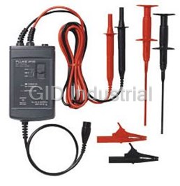
Probe, Voltage; Differential; 1.5 m long; CAT III/CAT II input
Part Number
DP120
Price
Request Quote
Manufacturer
FLUKE
Lead Time
Request Quote
Category
PROBES
Features
- Accuracy: ±2.5%
- Attenuation: 200x and 20x
- Bandwidth: DC to 20 MHz (-3 dB)
- Battery life: 8-hour operation, 400-hour stand by
- Battery type: Alkaline 9 volt, NEDA, IEC6LR61
- CMRR: 200x: @ 60 Hz = 80dB, @ 1 MHz = 50 dB 20x: @ 60 Hz = 70dB, @ 1 MHz = 40 dB
- Included Accessories: AC85A Large Jaw Alligator Clips and AC83 Pin-Grabber Test Clips
- Input: Probes with shrouded banana probe tip
- Maximum Differential Voltage: 1000V DC or1000Vrms or 1200V (DC + ACpeak)
- Maximum Input Voltage to Ground: 600V rms CAT III per IEC 1010-2-031 / 1000Vrms CAT II, per IEC 1010-2-031
- Output Cable: Safety designed 0.5m (5ft) BNC Cable
- Power Adapter: PM 8907/80n (optional)
- Probe length: 1.5 meter (60 inch)
- Rise time: 17.5 ns
Datasheet

Extracted Text
Using the DP120 Safely Using the DP120 Application of Testing an Adjustable ® To use the differential voltage probe, do the following: In this manual a Warning identifies conditions and actions that pose Speed Drive Timing Circuit hazards to the user. Symbols used on the DP120 and in this One of the tasks of the control circuitry in an adjustable speed drive instruction sheet are explained in the next table. (ASD) is timing of the output inverter switching. The voltage waveform of the pulse width modulated (PWM) output inverter is a See explanation in Conformité series of pulses of constant magnitude (height), but varying width. manual Européenne DP120 The control circuitry manages the timing of these pulses. Double Insulation UL3111 listed Differential Voltage Probe (Protection class) Recycle Instruction Sheet Warning Introducing the DP120 Do the following to avoid electrical shock or fire if the The DP120 is a safety designed differential voltage probe for probe is connected to more than 42V peak (30V rms): floating high voltage measurements. The probe can be used on electronic high-power converters, motor speed controls, switch • Use only Fluke power adapter, model PM8907 mode power supplies, and other high voltage circuits. When one of the stages of the output inverter does not function (option). c Connect the probe’s output cable to the desired input on properly, check the following: • Connect the power adapter to the AC outlet the test tool. For Fluke 123, use the black banana-to- before connecting it to the DP120. Unpacking BNC adapter (BB120). • the output stage • Do not insert metal objects in the power adapter Check that the following items are included with the DP120: • the control circuitry connector. d On the probe, select the 200x range. Ensure that the • DP120 - Differential Voltage Probe ® • Use 600V rated test lead adapters. The maximum green POWER ON-indicator is lit. The figure below shows how to connect a ScopeMeter test tool • AC85A - Large Jaw Alligator Clips (red and black) allowable input voltage is 600V, Category III. and a DP120 to the circuitry. • AC83 - Pin-Grabber Test Clips (red and black) e On the test tool, ensure that the probe correction is set to • 9V Alkaline Battery 200:1. If not available, set to 100:1. + Powering the DP120 f Connect both probe inputs to the measuring points. Follow the procedure (steps 1 to 3) to power the probe from a standard ac outlet. TOMOTOR g When the test tool is not in auto range, adjust the vertical range for optimal display. _ DCVOLTAGE h When using the 100:1 probe correction, multiply the voltage reading on the screen by 2x. i At completion, be sure to set the range selection switch to OFF again. Measurement tips: • Use the 20x range on the differential voltage probe for smaller signals, such as ripple on a high voltage reference lead. • At 20x range, set the test tool range to 20:1 (or 10:1). Note that the timing circuit for the FET (Field Effect Transistor) drive LIMITED WARRANTY & LIMITATION OF LIABILITY is referenced to earth ground. The gate drive signal is isolated with • When the probe is battery operated, the red LED indicates that This Fluke product will be free from defects in material and a transformer coupling to the FET, which is connected to the DC- the battery level is low and the battery needs to be replaced. workmanship for one year from the date of purchase. This warranty voltage. The power adapter is optional. For available Power Adapter models, does not cover fuses, disposable batteries or damage from • When battery operated, the probe automatically goes to An example of comparing the timing signal to the signal at the drive see the section ‘Servicing the DP120’. accident, neglect, misuse or abnormal conditions of operation or standby mode after 30 minutes to conserve battery power. A output can be seen in the screen below. handling. Resellers are not authorized to extend any other warranty blinking green LED indicates that the probe is in standby on Fluke’s behalf. To obtain service during the warranty period, mode. To continue operation, turn the range selection switch Storing the DP120 send your defective product to the nearest Fluke Authorized Service from OFF to 20x or 200x. If you are storing the differential voltage probe for an extended Center with a description of the problem. • Connect the red probe cable to a higher voltage level than the period of time, the battery should be removed and stored THIS WARRANTY IS YOUR ONLY REMEDY. NO OTHER black probe cable. separately. WARRANTIES, SUCH AS FITNESS FOR A PARTICULAR • For a dual measurement on test tool inputs A and B, connect PURPOSE, ARE EXPRESSED OR IMPLIED. FLUKE IS NOT the common to earth ground. This ensures optimal LIABLE FOR ANY SPECIAL, INDIRECT, INCIDENTAL OR measurement accuracy on all inputs. For operating and CONSEQUENTIAL DAMAGES OR LOSSES, ARISING FROM ANY grounding principles of the differential voltage probe, see the CAUSE OR THEORY. next figure. Since some states or countries do not allow the exclusion or limitation of an implied warranty or of incidental or consequential damages, this limitation of liability may not apply to you. Fluke Corporation Fluke Industrial B.V. P.O. Box 9090 P.O. Box 90 Everett WA 7600 AB Almelo 98206-9090, USA The Netherlands April 1997, Rev. 6, 4/10 © 1997, 1999, 2010 Fluke Corporation All rights reserved. Printed in the Netherlands All product names are trademarks of their respective companies. The DP120 conforms with the EEC directive 2004/108/EC for EMC Input Impedance: Characteristics immunity, as defined by IEC1000-4 -3, with the addition of the Installing or Replacing the Battery Between each input to shielding BNC: 5 MΩ , 6 pF following tables. FLUKE guarantees the properties expressed in numerical values Replace the battery when the red LED lights, or when both red and Between the inputs: 10 MΩ , 5 pF with the stated tolerance. Specified non-tolerance numerical values green LEDs are off when the probe is turned on. Output Impedance: 50Ω Table 1 indicate those that could be nominally expected from the mean of a range of identical differential voltage probes. Noise: Warning Susceptibility 200x: <2 mVrms To avoid electrical shock, disconnect the differential (in % of full dynamic range) Input Characteristics 20x: <3 mVrms voltage probe from any conductor, and disconnect ® Input Probe Tip Style: Shrouded banana probe tip the ScopeMeter test tool or oscilloscope before Offset: ≤10 mV into 1 MΩ Frequency range: E = 3 V/m E = 10 V/m replacing the battery. Probe Cable Length: 1.5 meter (60 inch) 10 kHz to 25 MHz Switch positions: OFF, 200x, 20x Follow the procedure (steps 1 to 5) to install or replace the battery. Maximum Input Voltage to Ground: Power 20x, 200x <1% <1% 600V CAT III External: 1000V CAT II Frequency range: E = 3 V/m E = 10 V/m Via power adapter PM8907 (optional) Installation Category III refers to distribution level and fixed 25 MHz to 1 GHz Internal: installation circuits inside a building. Installation Category II refers to local level, which is applicable for appliances, and portable Battery Power: Alkaline 9V, IEC6LR61 20x, 200x ≤1% ≤2% equipment. Battery Life: 8 hour operation 400 hour in auto standby Maximum Differential Input Voltage: ® Battery life measured @ 25 °C with Duracell alkaline 1000 VDC, or Table 2 battery. (Delivered with probe.) 1000 Vrms, or 1200V (DC+AC peak), whichever is smaller. Susceptibility Power indicators: (in % of full dynamic range) Green LED: ON at normal operation. Note blinks at standby. (DC+AC peak) limit is determined by the point at which Frequency range: E = 3 V/m E = 1 V/m To change from standby to normal operation turn switch the differential voltage probe starts clipping. 1.4 GHz to 2 GHz from OFF to 20x or 200x. For derating of each input probe (red or black), see figure below. Red LED: ON when battery needs to be replacing. 20x, 200x No visible --- disturbance Auto Stand By: After 30 minutes, only when battery operated. Frequency range: E = 3 V/m E = 1 V/m 2 GHz to 2.7 GHz Environmental Meets requirements of: 20x, 200x --- No visible MIL-T-28800E, Type III, Class 3. disturbance EN 50081-1, Electromagnetic Compatibility Generic Emission Standard: EN55022 and EN60555-2. Servicing the DP120 EN 50082-2, Electromagnetic Compatibility Generic Immunity For service information, contact your Fluke service center. To locate Standard: IEC1000-4 -2, -3, -4, -5. (see also Tables 1 and 2) an authorized service center, visit us on the World Wide Web: This product is in conformity with Electromagnetic Compatibility http://www.fluke.com Directive 2004/108/EC and Low Voltage Directive 2006/95/EC. This conformity is indicated by the symbol , i.e. “Conformité or call Fluke using any of the phone numbers listed below: Européenne”. +1-888-993-5853 in U.S.A. and Canada Output Characteristics Temperature: +31-40-2675200 in Europe Output Cable: Safety designed BNC cable Operating: 0°C to +50°C (+32°F to +122°F) +1-425-446-5500 from other countries Cable Length: 0.5 meter (20 inch) Storage: -10°C to +60°C (+14°F to +140°F) Max. Output Voltage Range: ±6.5V into 1 MΩ Available power adapters: Altitude: Operating: 3 km (9850 feet) Model Description Electrical Characteristics Storage: 12 km (40 000 feet) PM8907/801 Universal Europe 230V, 50 Hz Attenuation: 200x and 20x PM8907/803 North America 120V, 60 Hz Bandwidth: (into 1 MΩ , 50 pF) Safety Specifications 200x: DC to 20 MHz (-3 dB) PM8907/804 United Kingdom 240V, 50 Hz Meets requirements of: 20x: DC to 20 MHz (-3 dB) PM8907/806 Japan 100V, 60 Hz EN61010-2-31 (IEC1010-2-31). Accuracy: ±2.5% into 1 MΩ PM8907/807 Australia 240V, 50 Hz Compliant with: Rise time: PM8907/808 Universal 115V/230V UL3111-1 (including listing) 200x: 17.5 ns CSA C22.2 No.1010.1-92 (including approval) 20x: 17.5 ns Max. Floating Output Voltage: Note CMRR: 200x: @60Hz= >80 dB, @1 MHz= >50 dB 600V Category III, up to 400 Hz. (From shielding to ground.) The 230V rating of the PM8907/808 is not for use in North 20x: @60Hz= >70 dB, @1 MHz= >40 dB America. A line plug adapter complying with the applicable National Requirements may be provided to alter the blade configurations for a specific country. Service sheet: Ordering Number: 4822 872 05374
Frequently asked questions
What makes Elite.Parts unique?

What kind of warranty will the DP120 have?
Which carriers does Elite.Parts work with?
Will Elite.Parts sell to me even though I live outside the USA?
I have a preferred payment method. Will Elite.Parts accept it?


What they say about us
FANTASTIC RESOURCE
One of our top priorities is maintaining our business with precision, and we are constantly looking for affiliates that can help us achieve our goal. With the aid of GID Industrial, our obsolete product management has never been more efficient. They have been a great resource to our company, and have quickly become a go-to supplier on our list!
Bucher Emhart Glass
EXCELLENT SERVICE
With our strict fundamentals and high expectations, we were surprised when we came across GID Industrial and their competitive pricing. When we approached them with our issue, they were incredibly confident in being able to provide us with a seamless solution at the best price for us. GID Industrial quickly understood our needs and provided us with excellent service, as well as fully tested product to ensure what we received would be the right fit for our company.
Fuji
HARD TO FIND A BETTER PROVIDER
Our company provides services to aid in the manufacture of technological products, such as semiconductors and flat panel displays, and often searching for distributors of obsolete product we require can waste time and money. Finding GID Industrial proved to be a great asset to our company, with cost effective solutions and superior knowledge on all of their materials, it’d be hard to find a better provider of obsolete or hard to find products.
Applied Materials
CONSISTENTLY DELIVERS QUALITY SOLUTIONS
Over the years, the equipment used in our company becomes discontinued, but they’re still of great use to us and our customers. Once these products are no longer available through the manufacturer, finding a reliable, quick supplier is a necessity, and luckily for us, GID Industrial has provided the most trustworthy, quality solutions to our obsolete component needs.
Nidec Vamco
TERRIFIC RESOURCE
This company has been a terrific help to us (I work for Trican Well Service) in sourcing the Micron Ram Memory we needed for our Siemens computers. Great service! And great pricing! I know when the product is shipping and when it will arrive, all the way through the ordering process.
Trican Well Service
GO TO SOURCE
When I can't find an obsolete part, I first call GID and they'll come up with my parts every time. Great customer service and follow up as well. Scott emails me from time to time to touch base and see if we're having trouble finding something.....which is often with our 25 yr old equipment.
ConAgra Foods