

 Manufacturers
FLUKE 602927

Description
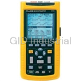
FLUKE-602927-DISPLAY
Part Number
602927
Price
Request Quote
Manufacturer
FLUKE
Lead Time
Request Quote
Category
PRODUCTS - 6
Specifications
Altitude Operating
2000 meters
Analog
31 segments, updates 25/sec
ANSI/ISA
S82.01-1994, EN 61010-1: 1993,
Battery Life
2000 hrs typical with alkaline
Battery Type
9 V NEDA 1604 or 6F22 or 006P,
Continuity Beeper
4096 Hz
CSA
C22.2 No 1010.1-92, UL 3111-1.
Display Digital
3,200 counts, updates 2.5/sec
Electromagnetic Compatibility
In RF field of 3 V/m on all functions.
EMC Regulations
EN 61326-1 1997.
Maximum Voltage
Rated voltage
Operating Temperature
0°C to 50°C
Relative Humidity
except 32 M?range
Response Time of Digital Display
V ac
Safety
600 V CAT III and 1000 V CAT II per
Shock Vibration
per MIL-T-PRF 28800F Class III, Sinusoidal,
Storage
12,000 meters
Storage Temperature
-40°C to 60°C
Temperature Coefficient
0.1 x (specified accuracy)/°C
Total accuracy
Specified accuracy + 0.1% of range.
Weight
365 g (12.9 oz)
Features
- (-) following the component reference designator. For example, pin 19
- attached parts.
- Circuit Nodes
- correspond to terms used on the schematic diagrams.
- display notation are presented in this manual as they are seen on the
- Individual pins or connections on a component are specified by a dash
- manual as “the meter”.
- meter.
- of U30 would be U30-19.
- Printed Circuit Assembly
- Special terms (mnemonics) used in text descriptions of meter circuitry
- The Fluke 77 Series III Multimeter is also referred to throughout this
- The term “pca” is used to represent a printed wiring board and its
- User Notation Generally, push buttons, function positions, input terminals, and
Datasheet

Extracted Text
® 77 Series III Multimeter Service Manual PN 800604 November 1998 Rev.1, 11/99 © 1998,1999 Fluke Corporation. All rights reserved. Printed in U.S.A. All product names are trademarks of their respective companies. Table of Contents Chapter Title Page 1 Introduction and Specifications................................. 1-1 1-1. Introduction ................................................................. 1-3 1-2. Organization of the Service Manual ........................... 1-3 1-3. Conventions ................................................................ 1-4 1-4. Specifications .............................................................. 1-4 2 Theory of Operation .................................................... 2-1 2-1. Introduction ................................................................. 2-3 2-2. Functional Block Description ..................................... 2-3 2-3. Detailed Description ................................................... 2-3 2-4. Voltage Signal Conditioning .................................. 2-3 2-5. Current Conditioning .............................................. 2-4 2-6. Ohms ....................................................................... 2-4 2-7. Additional Circuitry ................................................ 2-4 2-8. AC Converter ..................................................... 2-5 2-9. Active Filter ....................................................... 2-5 2-10. Rotary Switch ..................................................... 2-5 2-11. A/D Conversion .................................................. 2-5 3 Maintenance ................................................................ 3-1 3-1. Introduction ................................................................. 3-3 3-2. PCA Access and General Maintenance ...................... 3-3 3-3. Display Access ............................................................ 3-4 3-4. Cleaning ...................................................................... 3-4 3-5. Performance Test ........................................................ 3-7 3-6. Initial Procedure ..................................................... 3-7 3-7. DC Voltage Test ..................................................... 3-7 3-8. AC Voltage Test ......................................................... 3-8 3-9. Resistance Test ....................................................... 3-8 i 77 Series III Service Manual 3-10. Diode Test .............................................................. 3-9 3-11. DC mA Test ............................................................ 3-10 3-12. DC Amps Test ........................................................ 3-11 3-13. Calibration .............................................................. 3-11 3-14. Troubleshooting .......................................................... 3-11 3-15. Supplemental Troubleshooting Procedures ............ 3-13 3-16. Checking the Crystal Oscillator ......................... 3-13 3-17. Checking The Reference Voltage ...................... 3-13 3-18. Checking Display Drive Voltage ....................... 3-13 3-19. Checking Beeper Drive Signal ........................... 3-13 3-20. Tracing the VDC Signal Path ............................. 3-13 4 List of Replaceable Parts............................................ 4-1 4-1. Introduction ................................................................. 4-3 4-2. How to Obtain Parts .................................................... 4-3 4-3. Newer Instruments ...................................................... 4-3 4-4. Service Centers ........................................................... 4-3 4-5. Manual Status Information ......................................... 4-4 4-6. Parts Lists .................................................................... 4-4 5 Schematic Diagrams ................................................... 5-1 ii List of Tables Table Title Page 1-1. Specifications ..................................................................... 1-5 2-1. S1 Function Codes.............................................................. 2-6 3-1. Recommended Test Equipment.......................................... 3-3 3-2. DC Voltage Test................................................................. 3-8 3-3. AC Voltage Test................................................................. 3-8 3-4. Resistance Test................................................................... 3-10 3-5. DC mA Test........................................................................ 3-11 3-6. DC Amps Test .................................................................... 3-11 4-1. Final Assembly................................................................... 4-5 4-2. A1 Main PCA..................................................................... 4-7 5-1. Abbreviations ..................................................................... 5-3 iii 77 Series III Service Manual iv List of Figures Figure Title Page 2-1.Overview............................................................................2-3 2-2. AC and A/D Converter....................................................... 2-7 3-1. Assembly Details................................................................ 3-6 3-2. Troubleshooting Tree ......................................................... 3-12 4-2. A1 Main PCA..................................................................... 4-9 5-1. A1 Main PCA..................................................................... 5-4 v 77 Series III Service Manual vi OPERATOR SAFETY INFORMATION This instrument has been designed and tested in accordance with IEC Publication 348, Safety Requirements for Electronic Measuring Apparatus. This manual contains information and warnings which have to be followed by the user to ensure safe operation and to retain the instrument in safe condition. Warning statements identify conditions or practices that could result in personal injury or loss of life. Caution statements identify conditions or practices that could result in damage to the equipment or other property. • Never use the meter if the meter or test leads look damaged. • Always turn off power to the circuit before cutting, unsoldering, or breaking the circuit. Small amounts of current can be dangerous. • Never measure resistance in a circuit when power is applied to the circuit. • Never touch the probes to a voltage source when the test leads are plugged into the 10A or 300 mA input jack. • Never apply more than 1000V dc or ac rms (sine) between any input jack and earth ground. • Always be careful when working with voltages above 60V dc or 30V ac rms. Such voltages pose a shock hazard. • Always keep your fingers behind the finger guards on the probe when making measurements. • Always use a high voltage probe to measure voltage if the peak voltage might exceed 1000V. SAFETY-1 Symbols Marked on Equipment DANGER — High Voltage Attention — refer to the manual. This symbol indicates that information about the usage of a feature is contained in the manual. I Fuse information Use the Proper Fuse To avoid fire hazard, use only the fuse identical in type, voltage rating, and current rating as specified on the case bottom fuse rating label. Do Not Remove Cover Always operate the meter with case top and bottom properly assembled. Access procedures and the warnings for such procedures are contained in this Service Manual Service procedures are for qualified service personnel only. Do Not Attempt to Operate if Protection May be Impaired If the meter appears damaged or operates abnormally, protection may be impaired. Do not attempt to operate it. When is doubt, have the instrument serviced. SAFETY-2 Chapter 1 Introduction and Specifications Contents Page 1-1. Introduction.................................................................. 1-3 1-2. Organization of the Service Manual ............................ 1-3 1-3. Conventions ................................................................. 1-4 1-4. Specifications............................................................... 1-4 1-1 77 Series III Service Manual 1-2 Introduction and Specifications Introduction 1 1-1. Introduction This manual presents service information for the Fluke 77 Series III Multimeter. The manual includes a theory of operation, general maintenance procedures, performance tests, calibration procedures, troubleshooting information, a list of replaceable parts, and schematic diagrams. A meter under warranty will be promptly repaired or replaced (at Fluke’s option) and returned at no charge. See the registration card for warranty terms. To locate an authorized service center, visit us on the World Wide Web: www.fluke.com or call using any of the phone numbers listed below: USA: 1-888-99-FLUKE (1-888-993-5853) Canada: 1-800-36-FLUKE (1-800-363-5853) Europe: +31 402-678-200 Japan: +81-3-3434-0181 Singapore: +65-738-5655 Anywhere in the world: +1-425-446-5500 1-2. Organization of the Service Manual The following descriptions briefly describe each chapter in the manual. Chapter 1 Introduction and Specifications This chapter describes use of the Service Manual and application of special terminology (conventions) to describe the meter’s circuitry. A complete set of specifications appears at the end of this chapter. Chapter 2 Theory of Operation This chapter first categorizes instrument circuitry into functional blocks, with a description of each block’s role in overall operation. A detailed circuit description is then given for each block. These descriptions explore operation to the component level and fully support troubleshooting and repair procedures defined in Section 3. Chapter 3 Maintenance Provides complete maintenance information, from general maintenance and cleaning instructions to detailed troubleshooting and repair procedures to the component level. Troubleshooting and repair procedures rely heavily on both the Theory of Operation presented in Chapter 2 and the Schematic Diagrams shown in Section 5. Chapter 4 List of Replaceable Parts Includes parts lists for all standard assemblies. Information on how and where to order parts is also provided. Chapter 5 Schematic Diagrams Includes schematic for the A1 Main PCA. 1-3 77 Series III Service Manual 1-3. Conventions Through the manual, certain notational conventions are used. A summary of these conventions follow: • Instrument Reference The Fluke 77 Series III Multimeter is also referred to throughout this manual as “the meter”. • Printed Circuit Assembly The term “pca” is used to represent a printed wiring board and its attached parts. • Circuit Nodes Individual pins or connections on a component are specified by a dash (-) following the component reference designator. For example, pin 19 of U30 would be U30-19. • User Notation Generally, push buttons, function positions, input terminals, and display notation are presented in this manual as they are seen on the meter. Special terms (mnemonics) used in text descriptions of meter circuitry correspond to terms used on the schematic diagrams in Chapter 5. 1-4. Specifications Specifications for the meters are presented in Table 1-1. 1-4 Introduction and Specifications Specifications 1 Table 1-1. Specifications Maximum Voltage Between any Rated voltage Terminal and Earth Ground Display Digital: 3,200 counts, updates 2.5/sec Analog: 31 segments, updates 25/sec Response Time of Digital Display V ac < 2 s V dc < 1 s Ω < 1s to 320 kΩ, < 2s to 3.2 MΩ, < 10 s to 32 MΩ Operating Temperature 0°C to 50°C Storage Temperature -40°C to 60°C Temperature Coefficient 0.1 x (specified accuracy)/°C (<18°C or >28°C) Electromagnetic Compatibility In Total accuracy = Specified accuracy RF field of 3 V/m on all functions. + 0.1% of range. Relative Humidity except 32 MΩ range 0% to 90% (0°C to 35°C) 0% to 70% (35°C to 50°C) 32 MΩ range only 0% to 80% (0°C to 35°C) 0% to 70% (35°C to 50°C) Altitude Operating: 2000 meters Storage: 12,000 meters Battery Type 9 V NEDA 1604 or 6F22 or 006P, or NEDA 1604A or 6LR61 Battery Life 2000 hrs typical with alkaline 1600 hrs typical with carbon zinc Continuity Beeper 4096 Hz Shock, Vibration per MIL-T-PRF 28800F Class III, Sinusoidal, Non Operating Size (H x W x L) 3.7 cm x 8.9 - 7.8 cm x 19 cm (1.5 in x 3.5 - 3.1 in x 7.49 in) Weight 365 g (12.9 oz) Safety 600 V CAT III and 1000 V CAT II per ANSI/ISA S82.01-1994, EN 61010-1: 1993, CSA C22.2 No 1010.1-92, UL 3111-1. EMC Regulations EN 61326-1 1997. Certifications/Listings 1-5 77 Series III Service Manual Table 1-1. Specifications (cont) Function Range Accuracy 3.200 V ±(0.3%+1) L 32.00 V ±(0.3%+1) 320.0 V ±(0.3%+1) 1000 V ±(0.4%+1) L 320.0 mV ±(0.3%+1) m 3.200 V ±(2%+2) K (45 to 500 Hz, 32.00 V ±(2%+2) 3.2 V range. Other 320.0 V ±(2%+2) ranges 45 to 1 1000 V ±(2%+2) kHz) 320.0 Ω ±(0.5%+3) e 3200 Ω ±(0.5%+1) 32.00 kΩ ±(0.5%+1) 320.0 kΩ ±(0.5%+1) 3.200 MΩ ±(0.5%+1) 32.00 MΩ ±(2.0%+1) G R 2.0 V ±(1% typical) Function Range Accuracy Burden Voltage (typical) 32.00 mA, ±(2.5%+2) 6 mV/mA ? (45 Hz to 1 kHz) 320.0 mA ±(2.5%+2) 50 mV/A 10.00 A * 32.00 mA, ±(1.5%+2) 6 mV/mA A 320.0 mA ±(1.5%+2) 50 mV/A 10.00 A * * 10 A continuous, 20 A for 30 seconds maximum. 1-6 Introduction and Specifications Specifications 1 Overload protection for all functions and ranges: Rated voltage. Function Input Impedance (Nominal) L, L, K >10 MΩ, <50 pF m Common Mode Rejection Normal Mode Rejection Ratio (1 kΩ Unbalanced) L, L >120 dB at dc, 50 Hz, or 60 Hz >60 dB at 50 Hz or 60 Hz m >60 dB dc to 60 Hz K Open Circuit Test Voltage Full Scale Voltage To 3.2 MΩ 32 MΩ <3.1 V dc <440 mV dc <1.4 V dc e <2.8 V dc (typical) <420 mV dc <1.3 V dc (typical) (typical) Open Circuit Test Voltage Full Scale Voltage <3.1 V dc 2.0 V dc G R Short Circuit Current (typical) 300 μA e 400 μA G R V Current (typical) G F 0.0 V 0.4 mA 0.6 V 0.3 mA 1.2 V 0.2 mA 2.0 V 0.1 mA 1-7 77 Series III Service Manual 1-8 Chapter 2 Theory of Operation Contents Page 2-1. Introduction.................................................................. 2-3 2-2. Functional Block Description ...................................... 2-3 2-3. Detailed Description .................................................... 2-3 2-4. Voltage Signal Conditioning ................................... 2-3 2-5. Current Conditioning............................................... 2-4 2-6. Ohms........................................................................ 2-4 2-7. Additional Circuitry................................................. 2-4 2-8. AC Converter ...................................................... 2-4 2-9. Active Filter ........................................................ 2-5 2-10. Rotary Switch...................................................... 2-5 2-11. A/D Conversion................................................... 2-5 2-1 77 Series III Service Manual 2-2 ACV DCmV OFF ACmV Theory of Operation Introduction 2 2-1. Introduction This chapter contains a brief overview of the 77 Series III Multimeter, followed by a more detailed explanation of operation. 2-2. Functional Block Description The heart of the instrument consists of a two-chip CMOS system: U1, a primarily analog IC, and U2, a calculator-style microcomputer (see Figure 2- 1). Input S1 LCD Signal Conditioning J1 To Bar To Digital Graph Display Range and V REF Function Control A/D U2 Microcomputer Y1 A/D Samples Counter 32.768 kHz U1 Analog Chip aaa01f.eps Figure 2-1. Overview 2-3. Detailed Description The following paragraphs describe the 77 Series III Multimeter in more detail. While reading this description, refer to the schematic diagram in Chapter 5. 2-4. Voltage Signal Conditioning Input divider Z1 and dc blocking capacitor C1 make up an input voltage signal conditioning circuit. 2-3 OHMS 300 mV DCV 77 Series III Service Manual The pins of Z1 are used as follows: Z1-PIN NUMBER FUNCTION 1 input 3 3.2V range tap 4 32V range tap 5 320V range tap 6 1000V dc/750V ac range tap Overvoltage protection is provided by R1, RV1, RV2, RV3, and RT1. RT1 is a thermistor that normally has about 1 kΩ of resistance, but increases to very high impedance as it heats up with an overload voltage. R1 provides current limiting for the input until RT1 heats up. In an overload condition, RV1, RV2, and RV3 clamp the voltage at the switch to approximately 2000V. 2-5. Current Conditioning Current input conditioning is provided by R6, R7, R5 and R13. R6 and R7 develop input voltage from the applied current. R5 and R13 act as a voltage divider for the 300-mA range. F1 protects the mA circuitry; F3 protects the 10A circuitry. 2-6. Ohms When the ohms function is selected, the meter compares the unknown resistance at J1 with the reference resistors in Z1. Input protection for the ohms ranges consists of Q1, Q2, Q3, R1, R2, R3, R4, and RT1. Q1 and Q2 serve as back-to-back zener diodes which limit the input to between 7 and 9V. Also, R2 R3, and R4 limit current, and Q3 clamps pin 29 of U1 to approximately 2.5V. 2-7. Additional Circuitry In addition to the above circuitry, the following circuitry is also used in the Series II meters: AC Converter, Active Filter, Rotary Switch, and A/D Conversion. 2-8. AC Converter The ratio of R17 and R18 determines ac voltage and current accuracy (see Figure 2-2, AC and A/D Converter), and C11 is the averaging capacitor for the half-wave ac converter portion of U1. 2-4 Theory of Operation Detailed Description 2 2-9. Active Filter An active filter that includes R9, R10, C5, and C6 is located in U1. Conditioned input signals are passed through the active filter in route to the a/d converter section of U1. (See Figure 2-2, AC and A/D Converter.) The clock frequency for the digital portion of the circuit is a function of 32.768-kHz crystal Y1. Y1, C12, C15, and amplifiers in U1 make up the oscillator circuit. 2-10. Rotary Switch Rotary switch S1 FRONT selects and routes the input signals. Function codes for switch S1 REAR are shown in Table 2-1. Range switch S2 signals the microcomputer U2 for the manual ranging and automatic Touch Hold function. CR1 acts as protection for U1 if the battery is installed backwards. C2 is part of the power-on reset for microcomputer U2. 2-11. A/D Conversion Analog-to-digital (a/d) conversion is accomplished within U1 using a modified dualslope a/d converter circuit. (See Figure 2-2, AC and A/D Converter.) Since the a/d conversion process is essentially a dual slope method, two voltages are required to complete a measurement cycle. One is the unknown input and the other is the reference voltage. 2-5 77 Series III Service Manual Conditioned input signals are routed to the a/d converter in U1, where they are integrated. The reference voltage developed by reference supply VR1, R15, R16, and R8 is routed to the a/d converter in U1, where it is used for the integrate reference (de-integrate) portions of the measurement cycle. C7 stores offsets of the buffer, integrator, and comparator amplifiers of the a/d converter. The gain of the buffer is determined by the resistors of Z1 between pins 8, 9, and 10. C8 is the integrator capacitor. A series of 10 minor cycle conversions occurs without taking time for an autozero phase between the conversions. These minor cycle conversions, or samples, occur at a rate of 25 per second, and are used to provide the fast response bar-graph display and fast autoranging. New samples are taken every 40 ms. Ten samples are summed to produce a full- resolution digital display, with full scale greater than 3200 counts. A 50- ms autozero phase occurs following every 10 sample sequence. Table 2-1. S1 Function Codes Function B0 B1 B2 ACV 1 1 1 DCV 0 1 1 300 mV 0 0 0 Ohms 0 0 1 10 0 ACA 1 1 0 DCA 0 1 0 2-6 Theory of Operation Detailed Description 2 aaa03f.eps Figure 2-2. AC and A/D Converter 2-7 AC CONVERTER ACTIVE FILTER BUFFER INTEGRATOR COMPARATOR REF REF DE-INT + INT AC FILTER + + INPUT DIGITAL SECTION AC AC + + AC AC FILTER U1 16 17 28 26 39 40 27 44 45 46 47 R10 C7 C11 C5 C6 R9 C8 R17 Z1 Z1 + 10 9 8 R19 R18 + C9 77 Series III Service Manual 2-8 Chapter 3 Maintenance Contents Page 3-1. Introduction..................................................................... 3-3 3-2. PCA Access and General Maintenance .......................... 3-3 3-3. Display Access................................................................ 3-4 3-4. Cleaning .......................................................................... 3-4 3-5. Performance Test ............................................................ 3-7 3-6. Initial Procedure ......................................................... 3-7 3-7. DC Voltage Test ......................................................... 3-7 3-8. AC Voltage Test ............................................................. 3-8 3-9. Resistance Test ........................................................... 3-8 3-10. Diode Test .................................................................. 3-9 3-11. DC mA Test................................................................ 3-10 3-12. DC Amps Test ............................................................ 3-11 3-13. Calibration .................................................................. 3-11 3-14. Troubleshooting.............................................................. 3-11 3-15. Supplemental Troubleshooting Procedures................ 3-13 3-16. Checking the Crystal Oscillator ............................. 3-13 3-17. Checking The Reference Voltage .......................... 3-13 3-18. Checking Display Drive Voltage ........................... 3-13 3-19. Checking Beeper Drive Signal............................... 3-13 3-20. Tracing the VDC Signal Path................................. 3-13 3-1 77 Series III Service Manual 3-2 Maintenance Introduction 3 Warning These service instructions are for use by qualified personnel only. To avoid electric shock, do not perform any servicing other than that contained in the operator’s manual unless you are qualified to do so. 3-1. Introduction This chapter contains maintenance information for the performance testing, calibration, general maintenance, and troubleshooting of the 77 Series III Multimeter. For operator maintenance, refer to the Instruction Sheet. The performance tests are recommended as a preventive maintenance tool to verify proper instrument operation. A one year calibration cycle is recommended to maintain the specifications given in the Users Manual. Test equipment required for the performance tests and calibration is listed in Table 3-1. If the recommended equipment is not available, instruments with equivalent specifications may be used. Table 3-1. Recommended Test Equipment Instrument Type Recommended Model Multi-Product Calibrator Fluke 5500A 3-2. PCA Access and General Maintenance Warning To avoid electrical shock, remove the test leads before opening the case, and close the case before operating the meter. To prevent fire, install fuses with the rating shown on the back of the meter. Caution To avoid contaminating the pca with oil from the fingers, handle it by the edges or wear gloves. PCA contamination may not cause immediate instrument failure in controlled environments. Failures typically show up when contaminated units are operated in humid areas. Use the following procedure for removing the pca (printed circuit assembly) from its case: 3-3 77 Series III Service Manual 1. Set the function switch to OFF, and disconnect test leads if they are installed. 2. Remove the four Phillips screws from the bottom cover. 3. Turn the meter face up, grasp the top cover, and pull the top cover from the meter. 4. Remove the 11A fuse to access the screw that holds the pca to the case bottom. 5. The pca may now be removed from the bottom cover. 3-3. Display Access Caution Do not handle the conductive edges of the LCD interconnects. If contaminated, clean with alcohol. Refer to Figure 3-1. 1. Remove the four Phillips screws from the back side of the pca. 2. Remove the LCD mounting bracket. 3. Insert a small screwdriver under the edges of the display holding bracket, and gently pry the bracket loose from the snaps. 4. Turn the bracket upside down to remove the LCD. 5. Before installing a new LCD, make sure that all connector contact points are clean. 3-4. Cleaning Caution To avoid damaging the meter, do not use aromatic hydrocarbons or chlorinated solvents for cleaning. These solutions will react with the plastics used in instruments. Do not allow the LCD to get wet. Remove the display assembly before washing the pca and do not install until the pca is completely dry. Do not use detergent of any kind for cleaning the pca. Do not remove lubricants from the switch when cleaning the pca. 3-4 Maintenance Cleaning 3 Clean the instrument case with a mild detergent and water. The pca may be washed with isopropyl alcohol or deionized water and a soft brush. Remove the display assembly and fuses before washing, and avoid washing the switch if possible. Dry the pca with clean dry air at low pressure, then bake it at 50°C for 24 hours. 3-5 77 Series III Service Manual Decal Window Knob Assembly Case Top LCD Window Mask Bracket Shock Absorber LCD Detent Spring Elastomeric Connector Key Pad Internal Cover Shaft Adapter AC Shield Main PCA Screw, 4-24 F1 F2 Screw, 4-14 Bottom Shield Case Bottom Assembly Battery Annunciator Screw, 5-14 Contact Probe Holder Tilt Stand FLUKE-77-3 aaa12c.eps Figure 3-1. Assembly Details 3-6 Maintenance Performance Test 3 3-5. Performance Test Performance tests are recommended for incoming inspection, periodic maintenance, and for verifying the specifications in the Instruction Sheet. If the instrument fails any part of the test, calibration and/or repair is indicated. In the performance tests, the Fluke 77 Series III is referred to as the unit under test (UUT). 3-6. Initial Procedure 1. Allow the UUT to stabilize to room temperature 23°C ± 5°C (73°F ± 9°F). 2. Check the fuses and battery, and replace them if necessary. Warning To prevent fire, install fuses in accordance with the rating shown on the back of the meter. Warning To avoid false readings, which could lead to possible electric shock or personal injury, replace the battery as soon as the battery indicator (N) appears. 3-7. DC Voltage Test Warning Connect the ground/common/low side of the DC calibrator to COM on the UUT. 1. Set the UUT function switch to VDC, and connect the DC Voltage Calibrator output to the z and COM input terminals of the UUT. 2. Referring to Table 3-2, set the DC Voltage Calibrator for the output indicated in steps 1 through 4 only. Verify that the UUT display reading is within the limits shown. 3. Set the DC Voltage Calibrator for an output of +300 mV, and switch the UUT to the 300 mV function. Verify that the UUT display reading is within the limits shown in Table 3-2 (step 5). 3-7 77 Series III Service Manual Table 3-2. DC Voltage Test Step DC Input Voltage Display Reading 1 +2.7V 2.691 to 2.709V DC 2 +27V 26.91 to 27.09V DC 3 +270V 269.1 to 270.9V DC 4 +1000V 995 to 1005V DC 5* +300 mV 299.0 to 301.0V DC *300 mV function only 3-8. AC Voltage Test Warning Connect the ground/common/low side of the AC calibrator to COM on the UUT. 1. Set the UUT function switch to VAC, and connect the AC Voltage Calibrator to the z and COM input terminals. 2. Set the AC Voltage Calibrator for the output given in Table 3-3, verify that the UUT display reading is within the limits shown. Note When the input is open in the VAC function, it is normal for the meter to read some counts on the display. This is due to ac pickup in the ac amplifier when the ac amplifier when the ac amplifier is unterminated. Table 3-3. AC Voltage Test Input Step Voltage Frequency Display Reading 1 2.7V 100 Hz 2.644 to 2.756V AC 2 2.7V 500 Hz 2.644 to 2.756V AC 3 1000V 100 Hz 978 to 1022V AC 4 1000V 1000 Hz 978 to 1022V AC 3-9. Resistance Test 1. Select the ohms function on the UUT. 2. Connect the Ohms Calibrator or Decade Resistor to the z and COM input terminals of the UUT. 3-8 Maintenance AC Voltage Test 3 Referring to Table 3-4, set the Ohms Calibrator or Decade Resistor to the resistance value indicated in steps 1 through 6. Verify that the display reading is within the limits shown. 3-10. Diode Test 1. Set the UUT to the Diode Test function. Note On Fluke 5100 series calibrators, activate the 50Ω divider override. On Fluke 5500A calibrators, lock voltage to the 33V range. 2. Apply an input from the DC Voltage Calibrator of +.090V dc to the z and COM input terminals of the UUT, and verify that the beeper is on. 3. Increase the DC Voltage Calibrator output to +.110V dc, and verify that the beeper is off. 3-9 77 Series III Service Manual Table 3-4. Resistance Test Step Input Resistance Display Reading 1 short 0.0 to 0.3Ω Decades of 1: 2 100Ω 99.2 to 100.8Ω (plus 0 reading) 31kΩ 994 to 1006 Ω 4 10 kΩ 9.94 to 10.06 kΩ 5 100 kΩ 99.4 to 100.6 kΩ 61 MΩ .994 to 1.006 MΩ 7 10 MΩ 9.79 to 10.21 MΩ Decades of 1.9: 2 190Ω 188.7 to 191.3Ω (plus 0 reading) 3 1.9 kΩ 1889 to 1911 Ω 4 19 kΩ 18.89 to 19.11 kΩ 5 190 kΩ 188.9 to 191.1 kΩ 6 1.9 MΩ 1.889 to 1.9111 MΩ 7 19 MΩ 18.61 to 19.39 MΩ Decades of 2.7: 2 270Ω 268.3 to 271.7Ω (plus 0 reading) 3 2.7 kΩ 2685 to 2715Ω 4 27 kΩ 26.85 to 27.15 kΩ 5 270 kΩ 268.5 to 271.5 kΩ 6 2.7 MΩ 2.685 to 2.715 MΩ 7 27 MΩ 26.45 to 27.55 MΩ 3-11. DC mA Test 1. Set the output of the DC Current Calibrator to zero, and connect it to the 300mA and COM input terminals of the UUT. 2. Set the DC Current Calibrator to the output shown in Table 3-5, and verify that the UUT display reading is within the limits shown. 3-10 Maintenance Troubleshooting 3 Table 3-5. DC mA Test Step Input Current Display Reading 1 +27 mA 26.57 to 27.43 DC 2 +200 mA 196.8 TO 203.2 DC 3-12. DC Amps Test 1. Set the DC Current Calibrator to standby and connect it to the 10A and COM input terminals of the UUT. 2. Apply currents as indicated in Table 3-6, and verify that the display reading is within the limits shown. Table 3-6. DC Amps Test Step Input Current Display Reading 1 +10A 9.83 to 10.17 DC 3-13. Calibration 1. Set the DC Voltage Calibrator to zero, and set the UUT to the VDC function. 2. Remove the case top cover as previously described. 3. Connect the DC Voltage Calibrator to the zand COM input terminals of the UUT. 4. Set the DC Voltage Calibrator for an output of +3.000V dc, and adjust R8 for a display reading of +3.000V dc ± .001V. 3-14. Troubleshooting A troubleshooting tree for the meter is given in Figure 3-2. Faults are listed in the order of probability. This tree gives a systematic approach to isolation of problems to a component or component area. Complete the procedures in the order listed in this table; all measurements are made with respect to common. Also, supplemental troubleshooting procedures are presented in the following paragraphs. When troubleshooting the meter, use the precautions listed on the static awareness sheet to prevent damage from static discharge. 3-11 77 Series III Service Manual 1. Turn meter on Check: ON Does meter power up? a. Power supplies YES TP1 = 3.1V dc +/-0.1V TP3 = 1.5V dc U1 pin 48 = 6V dc (Battery voltage - TPIV) (If any of these voltages are high, low, or missing, replacement of U1 is usually necessary) b. For loose pins on U1, U2 c. Battery voltage d. S1 for bad contacts e. VR1 for 1.2V dc f. Shield for short to Q3 g. For solder debris/shortd 2. Meter powers up, but YES Check: does not come out of a. For loose pins on U1, U2 self-test. NO b. For shorted C5, 6, 7, or 8 c. Contacts of S1 d. For shorted pins on U1, U2 e. Y1 Frequency @ 32.768 kHz 3. Meter comes up with YES Check: missing segments. a. LCD for cracks NO b. For contaminated display interconnects or display contact areas c. For loose pins on U2 d. For cracks in U2 package e. Junction of R11 and R12 for 1.6V dc. 4. Switch meter to V and Probable cause: ON apply 3V dc. Does a. RV1 or RV2 or RV3 shorted meter display 3 VDC? YES b. S1 Contacts bad c. Z1 open or out of tolerance d. U1 bad e. U1 loose/shorted pins 5. Does meter autorange ON Probable cause: correctly? a. U1 bad YES b. S1 bad 6. Switch meter to V. Probable cause: YES Apply 3V @ 500 Hz. a. U1 bad (also check for loose or shorted pins) Does meter display b. S1 bad NO 3 VAC? c. C9, C11 shorted 7. Switch meter to . Probable cause: NO Apply 100 ohms. Does a. S1 bad meter display 100 ? b. Q1, Q2 shorted YES c. Loose pins on U1, U2 d. U1 bad 8. Switch meter to A. Probable cause: NO Apply 300 mA dc. Does a. F1, F2 open meter display 300 DC? YES b. S1 bad c. R7 open d. Open land patterns in current path 9. Switch meter to . Check: Does beeper sound NO a. Connector contact points when leads are b. For correct signal at contact points. Should be 4.1 kHz shorted? waveform. (If above checks are good, LS1 replacement is necessary.) aaa02f.eps Figure 3-2. Troubleshooting Tree 3-12 Maintenance Troubleshooting 3 3-15. Supplemental Troubleshooting Procedures 3-16. Checking the Crystal Oscillator Connect an oscilloscope or counter to pin 54 U1 or to the junction of C12 and the Y1 crystal. Check for a 32.768-kHz sine wave approximately 600 mV p-p in amplitude. Note that U2 and the display will not work if the clock circuit is not working. Probable related failures include: U1, Y1, or C12. 3-17. Checking The Reference Voltage Check for a reference voltage of 1.00V dc (adjustable by R8) at pin 14 of U1 or at the junction of R15 and R16. Probable related failures include: R8, R14, R15, R16, VR1, or CR2. 3-18. Checking Display Drive Voltage Check that VM (V middle) is 1.6V dc ±.1V at pin 28 U2 or at the junction of R11 and R12. Probable related failures include: R11 or R12. 3-19. Checking Beeper Drive Signal Put the unit in the Diode Test Mode and short the input leads. Using an oscilloscope, measure the signal at pin 3 of U1. The signal should be a 4V p-p symmetrical square wave at about 4.1 kHz. A probable related failure is: U1 3-20. Tracing the VDC Signal Path Use the following procedure to trace the VDC signal path: 1. Set the UUT to the VDC function and apply 2V dc to the input. 2. Using a DVM, measure the input at J1 for 2V dc. 3. Measure pin 1 of Z1 input divider for 2V dc. Probable related failures include: R1, S1, RV1, or RV2. Note Measurements in steps 4,5, and 6 may be affected by loading. 4. Measure Z1 pin 3 for 200 mV dc. Probable related failures are: Z1, U1. 5. Measure for 200 mV dc at the active filter input (AFI, pin 26 of U1 or R9). A probable failures is: U1 6. Measure for 200 mV at the active filter output (AFO, pin 27 of U1 or R9). Probable related failures are: R9, C5, or C6. 3-13 77 Series III Service Manual 3-14 static awareness A Message From Fluke Corporation Some semiconductors and custom IC's can be damaged by electrostatic discharge during handling. This notice explains how you can minimize the chances of destroying such devices by: 1. Knowing that there is a problem. 2. Leaning the guidelines for handling them. 3. Using the procedures, packaging, and bench techniques that are recommended. The following practices should be followed to minimize damage to S.S. (static sensitive) devices. 3. DISCHARGE PERSONAL STATIC BEFORE HANDLING DEVICES. USE A HIGH RESIS- TANCE GROUNDING WRIST STRAP. 1. MINIMIZE HANDLING 2. KEEP PARTS IN ORIGINAL CONTAINERS 4. HANDLE S.S. DEVICES BY THE BODY. UNTIL READY FOR USE. Static Awareness -1 5. USE STATIC SHIELDING CONTAINERS FOR 8. WHEN REMOVING PLUG-IN ASSEMBLIES HANDLE ONLY BY NON-CONDUCTIVE HANDLING AND TRANSPORT. EDGES AND NEVER TOUCH OPEN EDGE CONNECTOR EXCEPT AT STATIC-FREE WORK STATION. PLACING SHORTING STRIPS ON EDGE CONNECTOR HELPS PROTECT INSTALLED S.S. DEVICES. 6. DO NOT SLIDE S.S. DEVICES OVER ANY SURFACE. 9. HANDLE S.S. DEVICES ONLY AT A STATIC-FREE WORK STATION. 10. ONLY ANTI-STATIC TYPE SOLDER- SUCKERS SHOULD BE USED. 11. ONLY GROUNDED-TIP SOLDERING IRONS SHOULD BE USED. 7. AVOID PLASTIC,VINYL AND STYROFOAM IN WORK AREA. PORTIONS REPRINTED WITH PERMISSION FROM TEKTRONIX INC. AND GERNER DYNAMICS, POMONA DIV. Dow Chemical Static Awareness-2 Chapter 4 List of Replaceable Parts Contents Page 4-1. Introduction..................................................................... 4-3 4-2. How to Obtain Parts........................................................ 4-3 4-3. Newer Instruments .......................................................... 4-3 4-4. Service Centers ............................................................... 4-3 4-5. Manual Status Information ............................................. 4-4 4-6. Parts Lists........................................................................ 4-4 4-1 77 Series III Service Manual 4-2 List of Replaceable Parts Introduction 4 4-1. Introduction This section contains an illustrated list of replaceable parts for 77 Series III Multimeter. 4-2. How to Obtain Parts Electrical components may be ordered directly from the Fluke Corporation and its authorized representatives by using the part number under the heading FLUKE PN. In the U.S., order directly from the Fluke Parts Dept. by calling 1-800-526-4731. Parts price information is available from the Fluke Corporation or its representatives. Prices are also available in a Fluke Replacement Parts Catalog which is available on request. In the event that the part ordered has been replaced by a new or improved part, the replacement will be accompanied by an explanatory note and installation instructions, if necessary. To ensure prompt delivery of the correct part, include the following information when you place an order: • Part number and revision level of the pca containing the part. • Reference designator • Fluke stock number • Description (as given under the DESCRIPTION heading) • Quantity • Instrument Model, Serial Number, and Firmware Numbers 4-3. Newer Instruments Changes and improvements made to the instrument are identified by incrementing the revision letter marked on the affected pca. These changes are documented on a manual supplement which, when applicable, is included with the manual. 4-4. Service Centers To locate an authorized service center, call Fluke using any of the phone numbers listed below, or visit us on the World Wide Web: www.fluke.com USA: 1-888-99-FLUKE (1-888-993-5853) Canada: 1-800-36-FLUKE (1-800-363-5853) Europe: +31 402-678-200 Japan: +81-3-3434-0181 Singapore: +65-738-5655 Anywhere in the world: +1-425-446-5500 4-3 77 Series III Service Manual 4-5. Manual Status Information The following Manual Status Information table defines the assembly revision levels that are documented in the manual. Revision levels are printed on the component side of each pca. Manual Status Information Assembly Revision Level A1 Main PCA c 4-6. Parts Lists The following tables list the replaceable parts for the 77 Series III Multimeter. Parts are listed by assembly; alphabetized by reference designator. Each assembly is accompanied by an illustration showing the location of each part and its reference designator. The parts lists give the following information: • Reference designator • An indication if the part is subject to damage by static discharge • Description • Fluke stock number • Total quantity • Any special notes (i.e., factory-selected part) Caution A * symbol indicates a device that may be damaged by static discharge. Note This instrument may contain a Nickel-Cadmium battery. Do not mix with the solid waste stream. Spent batteries should be disposed of by a qualified recycler or hazardous materials handler. Contact your authorized Fluke service center for recycling information. Warning This instrument contains a fusible resistor (pn 740662). To ensure safety, use exact replacement only. 4-4 List of Replaceable Parts Parts Lists 4 Table 4-1. Final Assembly Ref Des Description Fluke PN Qty Notes A1 MAIN PCA NA 1 BT1 BATTERY,9V,0-15MA 696534 1 DS1 LCD,3.75 DIGIT,BAR GRAPH,MULTIPLED 602927 1 F1W FUSE,.406x1.375,0.440A,1000V,FAST 943121 1 F2W FUSE,.406X1.5, 11A, 1000V, FAST 803293 1 H1 SCREW,PH,P,THD FORM,STL,4-24,.250 519116 1 H2 SCREW,PH,P,AM THD FORM,STL,4-14,375 448456 5 H7 SCREW,PH,P,AM THD FORM,STL,5-14,.759 832246 4 LS1 AF TRANSD,PIEZO,20MM,600MW,6KHZ 642991 1 MP4 HOLDER,PROBE 648748 1 MP5 STAND,TILT 648961 1 MP6 LABEL,WINDOW 844337 1 MP9 SHIELD,AC 648755 1 MP10 SPRING,DETENT 822643 4 MP11 KNOB,SWITCH 648706 1 MP12 ADAPTER,SHAFT 649175 MP14 CASE BOTTOM ASSEMBLY 659786 1 MP16 SHOCK ABSORBER 428441 1 MP17 CASE TOP PAD XFR 648763 1 MP18 WINDOW, LCD 648714 1 MP19 COVER,INTERNAL 648722 1 MP20 MASK,BRACKET,77-3 WITH LOGO 648771 1 MP21 CONN,ELASTOMERIC,LCD TO PWB,1.900 L 650264 2 MP23 SHIELD,BOTTOM 648839 1 MP32 TEST LEADS TL75 1 MP40 CONTACT,ANNUNCIATOR 642983 1 S2 KEYPAD 648847 1 TM1 77/75/23/21 SERIES III INSTRUCTION 686571 1 SHEET TM2 77 SERIES III SERVICE MANUAL 800604 1 W To ensure safety, use exact replacement only. 4-5 77 Series III Service Manual MP6 MP11 MP17 MP18 MP20 MP16 DS1 MP10 MP21 S2 MP19 MP12 MP9 A1 H1 F1 F2 H2 MP23 MP14 BT1 MP40 LS1 H7 MP4 MP5 FLUKE-77-3 aaa05c.eps Figure 4-1. Final Assembly 4-6 List of Replaceable Parts Parts Lists 4 Table 4-2. A1 Main PCA Ref Des Description PN Qty. Notes C1 CAP,POLYES,0.0UF, ±10%,1000V 822361 1 C2,C3 CAP,CER,0.1UF, ±10%,25v,X7R 942529 2 C4 CAP,TA,2.2UF, ±20%,20V 854760 1 C5,C6 CAP,POLYCA,0.027UF, ±10%,63V 720979 2 C7 CAP,TA,0.47UF, ±20%,25V 876180 1 C8 CAP,POLYPR,0.033UF, ±10%,63V 721050 1 C9 CAP,TA,10UF, ±20%,10V,3528 603032 1 C10 CAP,CER,0.1UF, ±10%,25V,XR7 942529 1 C11 CAP,TA,2.2UF, ±20%,6V,3216 930248 1 C12 CAP,CER,47PF, ±5%,50V,C0G 494633 1 C13 CAP,CER,0.22UF,+80%,-20%,50V,Y5V 740597 1 C14,C15 CAP,CER,33PF, ±5%,50V,C0G 603172 1 C16 CAP,CER,47PF, ±5%,50V,COG 494633 1 CR1,CR2 * DIODE,SI,75V,250MA,SOT-23 830489 2 J1-4 RECEPTACLE,INPUT 658580 4 Q1,Q3 * XSTR,SI,NPN,25V,.3W,SEL,SOT-23 821637 2 Q2 * XSTR,SI,NPN,60V,350MW,SOT-23 742676 1 R1 RES,WW,3.5K, ±5%,5W,20PPM 107695 1 R2 RES,CERM,1K, ±5%,1W,200PPM 601176 1 R3 RES,CERM,1M, ±5%,1W 655175 1 R4 RES,CF,100K, ±1%,0.25W,100PPM 769802 1 R5 RES,MF,402K, ±0.25%,0.25W,50PPM 602664 1 R6 RES,WW,4.99, ±1%,5W 642923 1 R7 RES,WW,.005, ±1%,.5W 740415 1 R8 RES,VAR,CERM,100K, ±25% 912493 1 R9,R19 RES,CERM,1M, ±1%,0.125W,100PPM 836387 2 R10 RES,CERM,1.5M, ±1%,.1W,400PPM, 602703 1 R11,12 RES,MF,10K, ±1%,0.1W,100PPM 928791 2 R13 RES,MF,44.8K, ±0.25%,0.1W,50PPM 602679 1 R14 RES,CF,61.9K, ±1%,0.125W,100PPM 821330 1 R15 RES,MF,56.2K, ±1%,0.1W,100PPM 602687 1 R16 RES,MF,205K, ±1%,0.1W,100PPM 602935 1 R17 RES,CERM,20.5K, ±0.5%,100PPM 107711 1 R18 RES,CERM,9.2K, ±0.5%,100PPM 107745 1 RT1 THERMISTOR,POS,1.1K, ±+-20%,25 C 602995 1 RV1-,RV3 VARISTOR,910, ±+-10%,1.0MA 876193 3 S1 SWITCH,ROTARY 642918 1 U1 * IC CHIP 791269 1 U2 * IC, CMOS SM5A 603669 1 VR1 * IC, 1.23V,150 PPM T.C.,BANDGAP 634451 1 XBT1 BATTERY CONNECTOR 825976 1 XF1 CONTACT, FUSE 659524 2 4-7 77 Series III Service Manual Table 4-2. A1 Main PCA (cont) Ref Des Description PN Qty. Notes XF2 CONTACT, FUSE 707190 2 Y1 CRYSTAL,32.768KHZ, ±+-1%,3 X 8MM 643031 1 Z1 * RNET,CERM,SIP,FLUKE 77 HI V DIV. 946202 1 Z2 * RNET,CERM,SIP, HI V PROTECT 103454 1 4-8 List of Replaceable Parts Parts Lists 4 FLUKE 77-3-4001 aaa06f.eps Figure 4-2. A1 Main PCA 4-9 77 Series III Service Manual FLUKE 77-3-4001 aaa07f.eps Figure 4-2. A1 Main PCA (cont.) 4-10 Chapter 5 Schematic Diagrams 5-1 77 Series III Service Manual 5-2 Schematic Diagrams 5 Table 5-1. Abbreviations Abbreviation Definition ACA AC Converter Feedback ACHI AC Converter High ACL All Clear, Reset ACLO AC Converter Low AFI Active Filter Input AFO Active Filter Output AM0 Amp[s Input AM1 Amps Divide by 10 AZ Auto Zero Point BPR Beeper Driver BT Battery CLK Clock Output COM Common DCS DC Sense EC Reference Voltage FA0 Active Filter Amp Output FA(-) Active Filter Amp Feedback INT Integrator Oputput K0 Buffer x 1 Output K1 Buffer Divide by 3 Output LS Loud Speaker LO Low OHS Ohms Sense RNG Range RRS Reference Resistor Sense RT Thermistor VSS Negative Supply Voltage BDD Positive Supply Voltage VM Volts Middle WW Wirewound XTL Crystal Oscillator Inputs Z Impedance 5-3 77 Series III Service Manual FLUKE 77-3-4001 aaa06f.eps Figure 5-1. A1 Main PCA 5-4 Schematic Diagrams 5 FLUKE 77-3-4001 aaa07f.eps Figure. A1 Main PCA (cont) 5-5 77 Series III Service Manual OHMS,DT,CONT 9 GUARD 19 S1 GUARD Z2 1.0M 2MM 11 10 20 OHS 10 21 GUARD C14 11 33PF GUARD RV3 5% 910V RT1 1.5MM 1.1K 20% R2 C1 J1 R1 30 GUARD 1.0K 0.01 2MM 3.5K 5% 2MM Z1 VOLTS/ 12 31 V0 32 10M GUARD OHMS 6MM 4MM 5W 5% 1000V 3 33 V1 WW M 34 1000V Z1 1.1M GUARD 4 35 V2 S1 RV2 2 1 101K 5 36 V3 910V OHMS,VDC,MVDC 10K 6 37 V4 1MM 1.0K OHMS,DT 7 CONT,MVDC R4 100K S1 18 RRS 2 3 12 RV1 1% 910V MV R3 1.0M 29 DCS 42 F1 J2 R5 5% 1W 44/100A FAST 6MM 402K 0.25% 24 AM0 MA 1000V 0.25W MF R6 4.99 Q1 22 F2 AMI J3 5W SEL 11A FAST 6MM WW 7 10A S1 4 3 1000V VAC,VDC R7 8 .005 15 COM 1% 0.5W Q2 J4 WW MMBT3904 2 1 25 LO COMMON COM VDD Q3 SEL REFERENCE DESIGNATON R14 61.9K LAST NOT USED USED BT1 C15 CR2 CR2 BAS16 DS1 F2 J4 R15 LS1 56.2K 0.1W Q3 VR1 R19 R2 1.23V RT1 R16 RV3 205K 0.1W S3 TP3 TP2 R8 U2 2.7V 100K VR1 CAL 25% Y1 Z2 FLUKE 77-3-1001 aaa09f.eps Figure 5-1. A1 Main PCA (cont) 5-6 CW R13 44.8K 0.25% MF 0.1W 13 GUARD 41 GUARD 43 GUARD 300MA Schematic Diagrams 5 S1 96 TP1 VDD Y1 BT1 32.768KHZ 9V C12 C15 47PF 33PF CR1 C13 6 6 6 5% BAS16 0.22 5% LS1 S1 S1 S1 20% C16 4 5 12 47PF 54 5524 38 8 7 6 5 4 5% ON U1 AP75 FUNCTION CODE ANALOG PROCESSOR 49 D3 MOHMS OHMS OHMS 50 D2 VOLTAGE 3V,300K SOURCE D1 51 30V,30K D0 52 300V,3K CLK 56 1000V,300 NDAV 57 V DT,OHMS 58 C0 59 C1 OHMS C2 60 DE-INT C3 1 MA,10A DE-INT 14 EC TO RANGE DIGITAL SECTION AC ACTIVE CONVERTER FILTER BUFFER INTEGRATOR AC* INT LOW AC* FILTER* INT HIGH AC AC AC 16 17 28 26 39 40 27 44 45 46 47 C7 C8 R10 0.47 .033 1.50M C11 25V PP 63V 0.1W 9 2.2 C5 Z1 C6 6V .027 PC PC 63V 63V .027 10 8 R18 9.20K 0.5% C9 10 10V FLUKE 77-3-1001 aaa10f.eps Figure 5-1. A1 Main PCA (cont) 5-7 ACA R17 ACHI XTAL1 20.5K 0.5% R19 1.00M ACLO XTAL2 R9 1.00M AFI FA(-) TEST BPR FAO -VSS AFO X1 K1 +VDD 225K K0 X0.3 110K B0 AZ B1 INT B2 B3 COMPARATOR 77 Series III Service Manual C4 2.2 C10 20V 0.1 25V C3 0.1 25V 25 CK2 C2 19 RESET 0.1 3 DDC 25V 4 INTA 18 F 5 T 6 P00 7 P01 8 U2 P02 9 P03 10 P10 11 SMN3 P11 12 P12 13 P13 14 P20 15 P21 16 78 P22 H0 17 77 P23 H1 VDD TP3 R12 R11 10.0K 10.0K 0.1W 0.1W 1 2 HOLD S2 S3 2 1 DS1 LCD-PANTHER S1 POSITIONS PROCEDING CLOCKWISE M DESIGNATES MYLAR/POLYESTER FILM CAPACITOR CER DESIGNATES CERAMIC CAPACITOR FUNCTION TA DESIGNATES TANTALUM CAPACITOR CODE* PP DESIGNATES POLYPROPYLENE CAPACITOR FUNCTION B0 B1 B2 PC DESIGNATES POLYCARBONATE CAPACITOR WW DESIGNATES WIRE WOUND RESISTOR 1 OFF - - - MG DESIGNATES METAL GLAZE RESISTOR 2 AC VOLTS 1 1 1 MF DESIGNATES METAL FILM RESISTOR 3 DC VOLTS 0 1 1 CERM DESIGNATES CERMET FILM RESISTOR 4 300 MVDC 0 0 0 5 OHMS 0 0 1 6 DIODE TEST/CONTINUITY 1 0 0 7 AC CURRENT 1 1 0 8 DC CURRENT 0 1 0 *1=VDD 0=COMMON FLUKE 77-3-1001 aaa11f.eps Figure 5-1. A1 Main PCA (cont) 5-8 3 30 BG1 S0 4 31 BG3 S1 5 33 BG5 S2 6 34 23 BG7 S3 OSCIN 7 35 24 BG9 S4 OSCOUT 8 36 BG11 S5 9 37 BG13 S6 10 38 BG15 S7 11 57 BG17 S8 12 58 BG19 S9 BG21 13 59 S10 14 60 BG23 S11 15 49 BG25 S12 BG27 16 50 22 S13 T1 17 51 26 BG29 S14 T2 18 52 BG31 S15 22 53 AUTO S16 24 54 80 4A S17 VCC 25 55 4C 79 S18 VM 26 56 2 MAN S19 VDD 27 63 20 3D S20 VDD 28 27 3E S21 29 28 3A S22 30 29 3B S23 32 39 2D S24 33 42 2E S25 34 43 2A S26 35 44 2B S27 36 45 1D S28 37 46 1E S29 1A 38 47 S30 40 48 AC S31 2 64 +/- S32 65 K 19 S33 20 66 M S34 21 67 DC S35 23 68 HV S36 31 69 HOLD S37 39 70 BT S38 71 S39 73 S40 42 41 74 H1 H0 S41 32 GND 72 GND
Frequently asked questions
What makes Elite.Parts unique?

What kind of warranty will the 602927 have?
Which carriers does Elite.Parts work with?
Will Elite.Parts sell to me even though I live outside the USA?
I have a preferred payment method. Will Elite.Parts accept it?
Why buy from GID?

Quality
We are industry veterans who take pride in our work

Protection
Avoid the dangers of risky trading in the gray market

Access
Our network of suppliers is ready and at your disposal

Savings
Maintain legacy systems to prevent costly downtime

Speed
Time is of the essence, and we are respectful of yours
Related Products

635 Quickbert T1 handheld testset (635 Quickbert)
Request a Quote

The quote request has been received
Close

Facing challenges or have inquiries? Feel free to contact us!
Call Us +1-469-283-2440
What they say about us
FANTASTIC RESOURCE
One of our top priorities is maintaining our business with precision, and we are constantly looking for affiliates that can help us achieve our goal. With the aid of GID Industrial, our obsolete product management has never been more efficient. They have been a great resource to our company, and have quickly become a go-to supplier on our list!
Bucher Emhart Glass
EXCELLENT SERVICE
With our strict fundamentals and high expectations, we were surprised when we came across GID Industrial and their competitive pricing. When we approached them with our issue, they were incredibly confident in being able to provide us with a seamless solution at the best price for us. GID Industrial quickly understood our needs and provided us with excellent service, as well as fully tested product to ensure what we received would be the right fit for our company.
Fuji
HARD TO FIND A BETTER PROVIDER
Our company provides services to aid in the manufacture of technological products, such as semiconductors and flat panel displays, and often searching for distributors of obsolete product we require can waste time and money. Finding GID Industrial proved to be a great asset to our company, with cost effective solutions and superior knowledge on all of their materials, it’d be hard to find a better provider of obsolete or hard to find products.
Applied Materials
CONSISTENTLY DELIVERS QUALITY SOLUTIONS
Over the years, the equipment used in our company becomes discontinued, but they’re still of great use to us and our customers. Once these products are no longer available through the manufacturer, finding a reliable, quick supplier is a necessity, and luckily for us, GID Industrial has provided the most trustworthy, quality solutions to our obsolete component needs.
Nidec Vamco
TERRIFIC RESOURCE
This company has been a terrific help to us (I work for Trican Well Service) in sourcing the Micron Ram Memory we needed for our Siemens computers. Great service! And great pricing! I know when the product is shipping and when it will arrive, all the way through the ordering process.
Trican Well Service
GO TO SOURCE
When I can't find an obsolete part, I first call GID and they'll come up with my parts every time. Great customer service and follow up as well. Scott emails me from time to time to touch base and see if we're having trouble finding something.....which is often with our 25 yr old equipment.
ConAgra Foods