

 Manufacturers
FISHER CONTROLS 133HP
Description
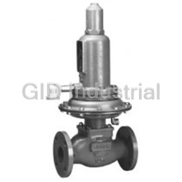
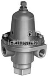
Fisher Controls 133HP Pressure Reducing, Self-Operated Regulator
Part Number
133HP
Price
Request Quote
Manufacturer
FISHER CONTROLS
Lead Time
Request Quote
Category
PRODUCTS - 1
Features
- Bubble-Tight Shutoff
- Easy Access to Trim Parts
- Excellent Shock Characteristics and Fast Speed of Response
- No Seat-to-Seat Adjustment Required
- Resistance to Piping Stresses
- Reusable Pressure Seals
- Spring and Diaphragm Effects Minimized
- Types 133L, 133H, 133Hp Suitable for Monitoring Application
- Wide Pressure Range Capability with Single Regulator
Datasheet

Extracted Text
Bulletin 71.1:133 January 2007 133 Series Self-Operated Regulators Features • Wide Pressure Range Capability with Single Regulator—Type 133H may also use Type 133L springs, allowing pressure settings to be varied between 2-inches w.c. and 10 psig (5 mbar and 0,69 bar) by changing springs. • Types 133L, 133H and 133HP Suitable for Monitoring Applications—O-ring stem seal on Types 133L, 133H and 133HP isolates body pressure from controlled pressure. • Excellent Shock Characteristics and Fast Speed of Response—Due to two-way stabilizer W1327/IL vent valve, which vents the spring case more TyPES 133H, 133L AND 133z REguLATORS rapidly than conventional vents, lag in diaphragm and valve disk movement is minimized. • Bubble-Tight Shutoff—Single-port construction, large diaphragm area, and light-rate springs along with disk material and seat design provide low lock-up pressures. • Spring and Diaphragm Effects Minimized boosting system provides excellent performance over a wide range of flow conditions. • No Seat-to-Seat Adjustment Required—Balanced single-port design eliminates necessity for seat-to seat adjustments to achieve bubble tight shutoff. • Easy Access to Trim Parts—Valve seat, disk, and cage easily removed with body remaining in line and without disassembly of actuator portion; orifice is not threaded in. • Reusable Pressure Seals—O-rings used for pressure seals, unlike gaskets, are not ordinarily damaged by disassembling the regulator. • Resistance to Piping Stresses—Steel W6803/IL constructions are available to help resist pipe stresses. TyPE 133HP REguLATOR Figure 1. 133 Series Self-Operated Regulators www.emersonprocess.com/regulators D100118X012 Bulletin 71.1:133 Specifications Available Configurations Type 133HP: 1/2-inch NPT female connection Type 133H: Self-operated regulator for inlet positioned directly over body inlet with a Fisher pressures to 60 psig (4,14 bar) and outlet Type Y602-7 pressures from 1.5 to 10 psig (0,10 to 0,69 bar), (1) Temperature Capabilities three ranges –20° to 150°F (–29° to 66°C) Type 133HP: Self-operated regulator for inlet pressures to 150 psig (10,3 bar) and outlet Flow Capacities pressures from 2 to 60 psig (0,14 to 4,14 bar), See Tables 3 through 10 seven ranges Wide-Open Flow Coefficients Type 133L: Self-operated regulator for inlet pressures to 60 psig (4,14 bar) and outlet WIDE-OPEN C FOR REPRESENTATIVE g CAPACITy pressures from 2-inches w.c. to 2 psig (5 mbar RELIEF VALVE SIzINg C 1 to 0,14 bar), six ranges (2) 25% 490 28.2 (2) 40% 760 29.1 Type 133z zero governor: Self-operated (2) 60% 1150 31.8 regulator for inlet pressures to 20 psig (1,38 bar) 100% 1800 35.0 and outlet pressures from –1 to 4-inches w.c. (–2,5 to 10 mbar), two ranges Construction Materials Body: Cast iron or Steel End Connections Orifice and Cage: Aluminum 2-inch (DN 50) Cast iron NPT female, cast iron Valve Disk: Aluminum/neoprene ANSI Class 125 flat-face flanged, steel NPT female O-Rings: Nitrile or steel ANSI Class 150 raised-face flanged Diaphragms: Nitrile/nylon (neoprene in actuator) (1) Maximum Inlet Pressures guide Bushing: Nylon See Table 2 Stem and Stem Sleeve: Stainless steel Diaphragm Plate: Steel (1) Outlet Pressure Ranges Balancing Diaphragm Plate: Plated steel See Table 1 Spring Case (1) Type 133HP: Cast Iron Maximum Outlet Pressures Types 133H, 133L and 133Z: Aluminum See Table 2 Lower Casing: Aluminum Pressure Registration Closing Cap: Cast iron External; downstream control line is required Adjusting Screw: Steel Optional Restriction Collar: Aluminum Control Line Connection Types 133H, 133L and 133z: 3/4-inch NPT Approximate Shipping Weight female; connection will be positioned directly over Types 133H, 133L and 133z NPT body outlet (standard position) or 90° right or left End Connections: 35 pounds (15,88 kg) of standard position if specified Types 133H, 133L and 133z Flanged Type 133HP: 1/4-inch NPT female connection End Connections: 40 pounds (18,14 kg) positioned directly over body outlet Type 133HP NPT End Connections: Vent Connection 56.5 pounds (25,63 kg) Types 133H, 133L and 133z: 1-inch NPT female Type 133HP Flanged End Connections: with screen; standard position is in line with 62.5 pounds (28,35 kg) control line connection directly over body outlet. Option Vent will always be positioned over the control Restriction collar to reduce wide-open capacity to line connection. approximately 25%, 40%, or 60% of standard wide-open capacity 1. None of the pressure/temperature limits in this bulletin, nor any applicable standard limitation, should be exceeded. 2. Using optional restriction collar. 2 Bulletin 71.1:133 W1213-1/IL W1212-1/IL TyPE 133z zERO gOVERNOR TyPE 133L LOW-PRESSuRE REguLATOR RESTRICTION COLLAR IDENTIFICATION SET SCREW gROOVE 1 ORIFICE CAgE W2215-1* E-RINg VALVE DISk TRIM PARTS WITH RESTRICTION COLLAR W1211-1 (40% CAPACITy COLLAR IS SHOWN) TyPE 133H WITHOuT RESTRICTION COLLAR 1 IDENTIFICATION gROOVES: 25% CAPACITy COLLAR—NO gROOVES 40% CAPACITy COLLAR—ONE gROOVE 60% CAPACITy COLLAR—TWO gROOVES Figure 2. Types 133Z, 133L and 133H Regulators 3 Bulletin 71.1:133 Introduction Description The 133 Series self-operated gas regulators, shown on the cover are primarily designed for industrial and commercial applications supplying gas to furnaces, burners and other appliances. The 133 Series balancing system enables the regulator to provide accurate control of gas pressure for maximum combustion efficiency despite varying inlet pressure conditions. The single port construction provides bubble tight shutoff. An external downstream control line is required for the operation of the regulator. Refer to Table 1 for outlet pressure ranges of each type. 133 Series regulators are available in a 2-inch (DN 50) body size with either threaded NPT or flanged end connections. An optional restriction collar (Figure 2) can be installed if wide-open capacity is too high for applications using a relief valve as overpressure protection. The collar reduces wide-open capacity to 25, 40, or 60% of standard wide-open capacity. Type 133H— —High pressure construction for outlet W6883/IL pressure range of 1.5 to 10 psig (0,10 to 0,69 bar). The Type 133H can also use the 2-inches w.c. to 2 psig Figure 3. Type 133HP Regulator (5 mbar to 0,14 bar) springs of the Type 133L. The maximum operating inlet pressure is 60 psig (4,14 bar) with a maximum emergency inlet pressure of 125 psig downstream system. Decreased demand increases (8,62 bar). the downstream pressure and moves the diaphragm Type 133HP— —Extra high pressure construction for outlet and stem assembly up, closing the valve disk and pressure range of 2 to 60 psig (0,14 to 4,14 bar). The decreasing the gas supply to the downstream system. maximum inlet pressure rating is 150 psig (10,3 bar). Boosting System Type 133L— —Low pressure construction for outlet pressure range of 2-inches w.c. to 2 psig (5 mbar to The 133 Series incorporates a balancing diaphragm 0,14 bar). The maximum operating inlet pressure is and a boosting system. When the regulator is locked 60 psig (4,14 bar) with a maximum emergency inlet up, inlet pressure is registered on the top of the valve pressure of 125 psig (8,62 bar). disk and on the bottom of the balancing diaphragm through registration holes in the top of the cage. Also, Type 133z— —Zero governor construction for outlet downstream pressure is registered on the bottom pressure range of –1 to 4-inches w.c. (–2,5 to of the valve disk and on the top of the balancing 10 mbar). The maximum operating inlet pressure is diaphragm through a passage formed by grooves in 20 psig (1,38 bar) with a maximum emergency inlet the registration disk and an annular space between the pressure of 125 psig (8,62 bar). stem and stem sleeve. When the valve disk is open, gas flows from the inlet Principle of Operation over the edge of the valve disk to the outlet. Under the valve disk near the registration disk, there is little Refer to the operational schematics in Figure 4. In gas flow. The gas pressure near the registration disk the 133 Series, downstream pressure is registered is higher than it is in the flow path where gas velocity under the diaphragm via the external control line and tends to lower the pressure. The higher pressure is used as the operating medium. Increased demand near the disk is registered on the top of the balancing lowers the downstream pressure and allows the spring diaphragm through the registration disk and the to move the diaphragm and stem assembly down, annular space between the stem and stem sleeve. opening the valve disk and supplying more gas to the 4 Bulletin 71.1:133 BALANCINg DIAPHRAgM B0098-3/IL A6980/IL INLET PRESSuRE REgISTRATION DISk BOOST PRESSuRE INLET PRESSuRE DOWNSTREAM PRESSuRE OuTLET PRESSuRE ATMOSPHERIC PRESSuRE TyPE 133L REguLATOR TyPE 133HP REguLATOR Figure 4. Operational Schematics This pressure registered on the top of the balancing Overpressure Protection diaphragm aids downward disk travel and compensates As is the case with most regulators, the 133 Series for spring and diaphragm effect. This improves regulators have outlet pressure ratings that are regulator rangeability and performance. lower than the inlet pressure ratings. Some type of Overpressure Protection is needed if the actual inlet Two-Way Stabilizer Vent Valve on pressure ever exceeds the outlet pressure rating. Types 133H, 133L and 133z Maximum inlet and outlet pressures for the 133 Series When the regulator responds to an increase in are given in Table 2. All models must be protected downstream pressure, the diaphragm moves upward. against inlet pressure above the maximum emergency As the diaphragm rises, movement of air forces the inlet pressure (refer to Table 2). lower vent flapper upward, carrying the upper flapper Outlet pressure more than 3 psig (0,21 bar) or 40 psig with it (see Figure 5). This allows the air above the (2,76 bar) for Type 133HP over the outlet pressure diaphragm to vent to atmosphere rapidly enough to setting of the regulator may damage internal parts minimize lag in diaphragm movement. such as the diaphragm plate and valve disk. As the diaphragm falls, air rushes in the vent to fill Regulator operation below these emergency pressure the partial vacuum created, forcing the upper vent limitations does not preclude the possibility of damage flapper against the orifice plate. Air flowing through from external sources or from debris in the gas line. the webs of the upper flapper opens the lower flapper The regulator should be inspected for damage after (see Figure 5). With the regulator at steady-state any overpressure condition. Complete instructions for conditions, both flappers are closed and only a small installation, operation, and maintenance are provided hole is open to help stabilize normal operation. with each regulator. 5 Bulletin 71.1:133 Table 1. 133 Series Outlet Pressure Ranges, Control Springs OuTLET PRESSuRE RANgE CONTROL SPRINgS TyPE Free Length, Wire Diameter, Inches w.c./Psig bar/mbar Part Number Color Code Stripe Inch (mm) Inch (mm) 1.5 to 3 psig 0,10 to 0,21 bar 1H975927032 Orange 7.37 (187) 0.250 (6,35) (1) 133H 2 to 5 psig 0,14 to 0,34 bar 10A9440X012 Yellow 6.47 (164) 0.283 (7,19) 5 to 10 psig 0,34 to 0,69 bar 1J146927142 Blue 6.19 (157) 0.375 (9,52) 2 to 5 psig 0,14 to 0,34 bar 17B8632X012 Yellow 8.5 (216) 0.281 (7,14) 4.5 to 10 psig 0,31 to 0,69 bar 17B8633X012 Orange 8.5 (216) 0.343 (8,71) 6 to 20 psig 0,41 to 1,38 bar 10C1238X012 Silver 8.25 (209) 0.406 (10,3) (1) 133HP 16 to 30 psig 1,10 to 2,07 bar 10C1240X012 Red 8.25 (209) 0.500 (12,7) 26 to 40 psig 1,79 to 2,76 bar 10C1241X012 Blue 8.25 (209) 0.500 (12,7) 36 to 50 psig 2,48 to 3,45 bar 10C1242X012 Green 8.25 (209) 0.531 (13,5) 45 to 60 psig 3,10 to 4,14 bar 10C1243X012 White 8.25 (209) 0.225 (5,72) 2 to 4-inches w.c. 5 to 10 mbar 1D892527022 Brown 6.12 (156) 0.109 (2,77) 3.5 to 6-inches w.c. 9 to 15 mbar 1D892627022 Red 7.5 (190) 0.120 (3,05) (1) 133L 5 to 9-inches w.c. 12 to 22 mbar 1D892727012 Black 7.87 (200) 0.130 (3,30) and 8.5 to 18-inches w.c. 21 to 45 mbar 1D893227032 White 7.5 (190) 0.156 (3,96) (2) 133H 14 to 28-inches w.c. 35 to 70 mbar 1D893327032 Green 7.25 (184) 0.182 (4,62) 0.75 to 2 psig 0,05 to 0,14 bar 1H975827032 Blue 7.37 (187) 0.225 (5,72) 1K633427012 -1 to 1-inch w.c. -2,5 to 2,5 mbar Black 2 (50,8) 0.075 (1,90) (Extension Spring) 1K633427012 Black 2 (50,8) 0.075 (1,90) (1) 133Z (Extension Spring) 0 to 4-inches w.c. 0 to 10 mbar and Brown 6.12 (156) 0.109 (2,77) 1D892527022 (Compression Spring) 1. Pressure ranges shown are correct if the regulator is installed with the actuator portion above the body portion. If the regulator is installed with the actuator portion below the body, the pressure ranges will be lowered by approximately 2-inches w.c. (5 mbar) for the Type 133L and by approximately 3-inches w.c. (7 mbar) for the Types 133H and 133Z. 2. If the 2-inches w.c. (5 mbar) to 2 psig (0,14 bar) springs (all 6 ranges) are used in the Type 133H, the pressure ranges will increase by approximately 1-inch w.c. (2 mbar) due to the weight of the Type 133H parts (assuming that the actuator is installed above the body). Table 2. Maximum Inlet and Outlet Pressures TyPE NuMBER PRESSuRES 133H 133HP 133L 133z Psig (bar) Psig (bar) Psig (bar) Psig (bar) Maximum Operating Inlet Pressure 60 (4,14) 150 (10,3) 60 (4,14) 20 (1,38) Maximum Emergency Inlet Pressure 125 (8,62) 150 (10,3) 125 (8,62) 125 (8,62) Setpoint Plus 4-inches w.c. (1) Maximum Operating Outlet Pressure 10 (0,69) 2 (0,14) 40 psi (2,76 bar) (10 mbar) Maximum Outlet Pressure Over 3 (0,21) - - - - 3 (0,21) 3 (0,21) Outlet Pressure Setting Maximum Emergency Outlet 15 (1,03) 150 (10,3) 15 (1,03) 15 (1,03) (Casing) Pressure 1. With highest spring range available only. For restricted-capacity constructions, determine flow Capacity Data capacities for outlet pressure settings of 2 psig Flow capacities for various inlet pressures and (0,14 bar) or less by multiplying the values from outlet pressure settings are shown in Tables 3 to 10. Tables 3 to 10 by 25, 40, or 60% (depending upon Capacities for Tables 3 to 10 are in thousands of cubic which restriction collar is selected). For pressure feet per hour of 0.6 specific gravity gas at 60°F and settings over 2 psig (0,14 bar), capacities are given 14.7 psia. To convert to equivalent capacities of other in Table 6. If flow capacities for inlet pressures lower gases, multiply the values shown by the appropriate than those shown are required, contact the Sales factor: air–0.775; propane–0.628, butane–0.548; Representative. The representative regulating C g nitrogen–0.789. of 1650 may be used for regulator sizing of full- capacity constructions only if capacity table data is Note not available. The representative regulating C is an g approximation only for pressure drops greater than For optimum performance, select the 5 psi (0,34 bar), because, at a given offset in controlled lowest spring range that includes the pressure, the regulating C varies with the spring being g desired outlet pressure setting. used with the pressure drop across the valve. 6 Bulletin 71.1:133 W1032-1/IL W1902-1/IL TWO-WAy STABILIzER VENT VALVE IN “uP” POSITION VENT VALVE IN “DOWN” POSITION AS DIAPHRAgM RISES AS DIAPHRAgM LOWERS Figure 5. Types 133H, 133L and 133Z Stabilizer Vent To determine capacity using the flow coefficient C , A remote vent line may be required for some g use the appropriate procedure below. installations. Vent openings must be protected against the entrance of rain, snow, insects, or any other 1. If flow is critical (absolute outlet pressure is equal foreign material that may plug the vent. to or less than one-half the absolute inlet pressure), use the equation: External dimensions are shown in Figure 9. Capacity = (Absolute Inlet Pressure) (C ) (1.29) g Ordering Information The capacity determined will be in standard cubic feet per hour of 0.6 specific gravity gas. When ordering, specify: 2. If flow is less than critical (absolute outlet pressure Application is greater than one-half the absolute inlet pressure), use the Fisher sizing slide rule or the 1. Type of gas being controlled (natural gas, air, etc.): sizing nomographs in Fisher Catalog 10 to list any factors such as impurities in the gas that determine capacity. may affect compatibility of the gas with the regulator trim parts. Table 3. Full-Capacity Type 133Z Regulated Flow in Thousands of SCFH of (0.6 Specific Gravity Gas at 14.7 Psia 2. Specific gravity of the gas and 60°F) 3. Temperature of the gas 1-INCH W.C. (2,5 mbar) OuTLET (1) PRESSuRE SETTINg 4. Range of flowing inlet pressures to regulator (EITHER SPRINg RANgE) INLET PRESSuRE 5. Outlet pressure 0.5-inch w.c. 1-inch w.c. (1 mbar) Droop (2,5 mbar) Droop 6. Flow rates 3 3 SCFH (Nm /h) SCFH (Nm /h) 8-inches w.c. (20 mbar) 2.4 (0,06) 5.1 (0,14) a) Minimum controlled flow 14-inches w.c. (35 mbar) 4.1 (0,11) 7.4 (0,20) 1 psig (0,07 bar) 6.5 (0,17) 12 (0,32) b) Normal flow 2 psig (0,14 bar) 11.5 (0,31) 18 (0,48) c) Maximum flow 5 psig (0,34 bar) 22 (0,59) 32 (0,86) 10 psig (0,69 bar) 44 (1,18) 50 (1,34) 7. Line size and end connection size of adjacent piping 20 psig (1,38 bar) 76 (2,04) 78 (2,09) 1. Outlet pressure setting was made at approximately 10% of the maximum capacity for the listed conditions. Regulator Installation Refer to the Specifications section on page 2. Carefully review the description to the right of each The regulator may be installed in any position but is specification and in the referenced tables. Specify normally installed with the actuator portion vertical the desired selection wherever there is a choice to be above the body portion. Flow through the body must made. Always specify the regulator type number. be in the direction indicated by the flow direction arrow cast on the body portion. A downstream control line is required for operation of the regulator. 7 Bulletin 71.1:133 Table 4. Full-Capacity Type 133L Regulated Flow in Thousands of SCFH of 0.6 Specific Gravity Gas at 14.7 Psia and 60°F (1) OuTLET PRESSuRE SETTINg , SPRINg PART NuMBER, AND OuTLET PRESSuRE RANgE 4-inches w.c. 6-inches w.c. 7-inches wc (10 mbar) (15 mbar) (17 mbar) 14-inches w.c. 14-inches w.c. 1 Psig (0,07 bar) 2 Psig (0,14 bar) 1D892527022 1D892627022 1D892727012 (35 mbar) (35 mbar) 1D893327032 1H975827032 2 to 4 3.5 to 6 5 to 9 1D893227032 1D893227032 14 to 28-inches w.c. 0.75 to 2 psig INLET inches w.c. inches w.c. inches w.c. 8.5 to 18-inches w.c. 14 to 28-inches w.c. (35 to 70 mbar) (0,05 to 0,14 bar) PRESSuRE, (5 to 10 (8,7 to 15 (12 to 22 (21,2 to 44,8 mbar) (35 to 70 mbar) PSIg (bar) mbar) mbar) mbar) 1-inch w.c. 1-inch w.c. 1-inch w.c. 1-inch w.c. 2-inch w.c 1-inch w.c. 2-inch w.c. 10% 20% 10% 20% (2,5 mbar) (2,5 mbar) (2,5 mbar) (2,5 mbar) (5 mbar) (2,5 mbar) (5 mbar) Droop Droop Droop Droop Droop Droop Droop Droop Droop Droop Droop SCFH SCFH SCFH SCFH SCFH SCFH SCFH SCFH SCFH SCFH SCFH 3 3 3 3 (Nm /h) (Nm /h) (Nm /h) (Nm /h) 3 3 3 3 3 3 3 (Nm /h) (Nm /h) (Nm /h) (Nm /h) (Nm /h) (Nm /h) (Nm /h) 1 (0,07) 14 (0,38) 13 (0,35) 12 (0,32) 5 (0,13) 8.4 (0,22) - - - - - - - - - - - - - - - - - - - - - - - - 2 (0,14) 20.8 (0,56) 20 (0,54) 17 (0,46) 8.2 (0,22) 15.2 (0,41) - - - - - - - - 11.5 (0,31) 16 (0,43) - - - - - - - - 3 (0,21) 26 (0,70) 24.5 (0,66) 21 (0,56) 12 (0,32) 19.5 (0,52) - - - - - - - - 15.5 (0,42) 21.5 (0,58) 12.5 (0,34) 18.5 (0,50) 5 (0,34) 35 (0,94) 33 (0,88) 32 (0,86) 16 (0,43) 28 (0,75) 14 (0,38) 23 (0,62) 24 (0,64) 31.5 (0,84) 20.5 (0,55) 28 (0,75) 10 (0,69) 52 (1,39) 52 (1,39) 48 (1,29) 34 (0,91) 45 (1,21) 26 (0,70) 38 (1,02) 37.5 (1,00) 44 (1,18) 38 (1,02) 46 (1,23) 20 (1,38) 78 (2,09) 77 (2,06) 79 (2,12) 69 (1,85) 76 (2,04) 60 (1,61) 69 (1,85) 70 (1,88) 77 (2,06) 62 (1,66) 76 (2,04) 30 (2,07) 101 (2,71) 100 (2,68) 100 (2,68) 91 (2,44) 97 (2,60) 87 (2,33) 93 (2,49) 90 (2,41) 101 (2,71) 87 (2,33) 101 (2,71) 40 (2,76) 124 (3,32) 122 (3,27) 124 (3,32) 109 (2,92) 116 (3,11) 107 (2,87) 115 (3,08) 110 (2,95) 122 (3,27) 105 (2,81) 121 (3,24) 50 (3,45) 146 (3,91) 144 (3,86) 145 (3,89) 130 (3,48) 136 (3,64) 132 (3,54) 137 (3,67) 127 (3,40) 145 (3,89) 124 (3,32) 145 (3,89) 60 (4,14) 170 (4,56) 168 (4,50) 166 (4,45) 155 (4,15) 161 (4,32) 152 (4,07) 158 (4,23) 149 (3,99) 167 (4,48) 145 (3,89) 170 (4,56) 1. Outlet pressure setting was made at approximately 10% of the maximum capacity for the listed conditions. Table 5. Full-Capacity Type 133H Regulated Flow in Thousands of SCFH of (0.6 Specific Gravity Gas at 14.7 Psia and 60°F) (1) OuTLET PRESSuRE SETTINg , SPRINg PART NuMBER, AND OuTLET PRESSuRE RANgE 3 Psig (0,21 bar) 2 Psig (0,14 bar) 5 Psig (0,34 bar) 5 Psig (0,34 bar) 10 Psig (0,69 bar) 1H975927032 10A9440X012 10A9440X012 1J146927142 1J146927142 INLET 1.5 to 3 Psig 2 to 5 Psig 2 to 5 Psig 5 to 10 Psig 5 to 10 Psig PRESSuRE, (0,10 to 0,21 bar) (0,14 to 0,34 bar) (0,14 to 0,34 bar) (0,34 to 0,69 bar) (0,34 to 0,69 bar) PSIg (bar) 10% 20% 10% 20% 10% 20% 10% 20% 10% 20% Droop Droop Droop Droop Droop Droop Droop Droop Droop Droop SCFH SCFH SCFH SCFH SCFH SCFH SCFH SCFH SCFH SCFH 3 3 3 3 3 3 3 3 3 3 (Nm /h) (Nm /h) (Nm /h) (Nm /h) (Nm /h) (Nm /h) (Nm /h) (Nm /h) (Nm /h) (Nm /h) 3 (0,21) - - - - - - - - 6.5 (0,17) 11.5 (0,31) - - - - - - - - - - - - - - - - - - - - - - - - 5 (0,34) 14 (0,38) 22 (0,59) 11 (0,30) 18 (0,48) - - - - - - - - - - - - - - - - - - - - - - - - 7 (0,48) 21.5 (0,58) 31 (0,83) 13 (0,35) 22 (0,59) 15.5 (0,42) 24 (0,64) 9 (0,24) 15 (0,40) - - - - - - - - 10 (0,69) 28 (0,75) 42 (1,13) 15 (0,40) 27 (0,72) 24 (0,64) 35 (0,94) 14 (0,38) 22 (0,59) - - - - - - - - 15 (1,03) 40 (1,07) 57 (1,53) 25.5 (0,68) 39 (1,04) 35 (0,94) 51 (1,37) 19 (0,51) 31.5 (0,84) 21 (0,56) 35 (0,94) 20 (1,38) 52 (1,39) 72 (1,93) 35 (0,94) 52 (1,39) 46 (1,23) 67 (1,80) 24 (0,64) 41 (1,10) 31 (0,83) 51 (1,37) 30 (2,07) 76 (2,04) 96 (2,57) 49 (1,31) 73 (1,96) 68 (1,82) 95 (2,55) 35 (0,94) 58 (1,55) 44 (1,18) 74 (1,98) 40 (2,76) 98 (2,63) 119 (3,19) 66 (1,77) 97 (2,60) 88 (2,36) 117 (3,14) 44 (1,18) 73 (1,96) 56 (1,50) 97 (2,60) 50 (3,44) 118 (3,16) 141 (3,78) 84 (2,25) 112 (3,00) 103 (2,76) 138 (3,70) 57 (1,53) 89 (2,38) 74 (1,98) 117 (3,14) 60 (4,14) 136 (3,64) 165 (4,42) 104 (2,79) 132 (3,54) 122 (3,27) 156 (4,18) 65 (1,74) 106 (2,84) 91 (2,44) 136 (3,64) 1. Outlet pressure setting was made at approximately 10% of the maximum capacity for the listed conditions. 8 Bulletin 71.1:133 CAPACITy AND REguLATION CAPACITy AND REguLATION 2-INCH (DN 50) TyPE 133z 2-INCH (DN 50) TyPE 133L SPRINg 1D893327032 SPRINg COMPRESSION - 1D892527022 EXTENSION - 1k663427012 SETPOINT: INLET PRESSuRE 40 PSIg (2,76 bar) SETPOINT: INLET PRESSuRE 1 PSIg (0,07 bar) OuTLET PRESSuRE 1 PSIg (0,07 bar) OuTLET PRESSuRE 1-INCH W.C. (2 mbar) 3 FLOW 11000 SCFH (295 Nm /h) 3 1.2 (0,08) FLOW 3000 SCFH (80,4 Nm /h) 3 (7) 1.0 (0,07) 0.8 (0,06) 2 (5) 1 (2) 0.6 (0,04) 0.4 (0,03) 0 (0) 20 PSIg 30 PSIg 40 PSIg 50 PSIg 60 PSIg 1 PSIg 2 PSIg 5 PSIg 10 PSIg 20 PSIg (1,38 bar) (2,07 bar) (2,76 bar) (3,45 bar) (4,14 bar) 0.2 (0,01) (0,07 bar) (0,14 bar) (0,34 bar) (0,69 bar) (1,38 bar) 21A0871–A 21A0868–A 0 10 20 30 40 50 60 70 80 90 0 20 40 60 80 100 120 140 160 180 (0) (25) (50) (75) (99) (124) (149) (174) (199) (224) (0) (1,38) (2,76) (4,14) (5,52) (6,90) (8,27) (9,65) (11,0) (12,4) CAPACITy AND REguLATION CAPACITy AND REguLATION 2-INCH (DN 50) TyPE 133L SPRINg 1D892727012 2-INCH (DN 50) TyPE 133L SPRINg 1D893327032 SETPOINT: INLET PRESSuRE 2 PSIg (0,14 bar) SETPOINT: INLET PRESSuRE 40 PSIg (2,76 bar) OuTLET PRESSuRE 7-INCH W.C. (17 mbar) OuTLET PRESSuRE 1 PSIg (0,07 bar) 3 3 FLOW 3100 SCFH (83,08 Nm /h) FLOW 11000 SCFH (295 Nm /h) 10 (25) 8 (20) 3 (0,21) 6 (15) 4 (10) 2 (0,14) 2 (5) 20 PSIg 40 PSIg 60 PSIg 1 PSIg 2 PSIg 3 PSIg 5 PSIg (1,38 bar) (2,76 bar) (4,14 bar) (0,07 bar) (0,14 bar) (0,21 bar) (0,34 bar) 1 (0,07) 21A0865–A 0 4 8 12 16 20 24 28 32 36 21A0869–A 0 20 40 60 80 100 120 140 160 180 (0) (10) (20) (30) (40) (50) (60) (70) (79) (90) (0) (1,38) (2,76) (4,14) (5,52) (6,90) (8,27) (9,65) (11,0) (12,4) CAPACITy AND REguLATION CAPACITy AND REguLATION 2-INCH (DN 50) TyPE 133H SPRINg 10A9440X012 2-INCH (DN 50) TyPE 133L SPRINg 1D892727012 SETPOINT: INLET PRESSuRE 40 PSIg (2,76 bar) SETPOINT: INLET PRESSuRE 40 PSIg (2,76 bar) OuTLET PRESSuRE 5 PSIg (0,34 bar) OuTLET PRESSuRE 7-INCH W.C. (17 mbar) 3 3 FLOW 11000 SCFH (295 Nm /h) FLOW 11000 SCFH (295 Nm /h) 10 (25) 6 (0,41) 8 (20) 5 (0,35) 6 (15) 4 (10) 4 (0,28) 3 (0,21) 2 (5) 10 PSIg 20 PSIg 30 PSIg 40 PSIg 50 PSIg 60 PSIg 20 PSIg 30 PSIg 40 PSIg 50 PSIg 60 PSIg 2 (0,14) (0,69 bar) (1,38 bar) (2,07 bar) (2,76 bar) (3,45 bar) (4,14 bar) (1,38 bar) (2,07 bar) (2,76 bar) (3,45 bar) (4,14 bar) 21A0865–A 21A0870–A 0 20 40 60 80 100 120 140 160 180 0 20 40 60 80 100 120 140 160 180 (0) (50) (99) (149) (199) (249) (298) (348) (398) (448) (0) (1,38) (2,76) (4,14) (5,52) (6,90) (8,27) (9,65) (11,0) (12,4) CAPACITy AND REguLATION 2-INCH (DN 50) TyPE 133L SPRINg 1D832727032 SETPOINT: INLET PRESSuRE 40 PSIg (2,76 bar) 18 (45) OuTLET PRESSuRE 14-INCH W.C. (35 mbar) 3 FLOW 11000 SCFH (295 Nm /h) 16 (40) 3 NOTE: FLOW RATE - 1000 SCFH (26,8 Nm /h) 14 (34) 0.6 SPECIFIC gRAVITy gAS AT 14.7 PSIA AND 60°F 12 (30) 10 (25) 8 (20) 10 PSIg 20 PSIg 40 PSIg 60 PSIg 6 (15) (0,69 bar) (1,38 bar) (2,76 bar) (4,14 bar) 21A0867–A C0744/IL 0 20 40 60 80 100 120 140 160 180 (0) (50) (99) (149) (199) (249) (298) (348) (398) (448) Figure 6. Capacity Curves — Full-Capacity Constructions 9 OuTLET PRESSuRE OuTLET PRESSuRE OuTLET PRESSuRE OuTLET PRESSuRE INCHES W.C. (mbar) INCHES W.C. (mbar) INCHES W.C. (mbar) INCHES W.C. (mbar) OuTLET PRESSuRE OuTLET PRESSuRE OuTLET PRESSuRE PSIg (bar) PSIg (bar) PSIg (bar) Bulletin 71.1:133 CAPACITy AND REguLATION CAPACITy AND REguLATION 2-INCH (DN 50) TyPE 133L 2-INCH (DN 50) TyPE 133L SPRINg 1D892727012 25% CAPACITy TRIM SPRINg 1H975827032 25% CAPACITy TRIM SETPOINT: INLET PRESSuRE 20 PSIg (1,38 bar) SETPOINT: INLET PRESSuRE 20 PSIg (1,38 bar) OuTLET PRESSuRE 7-INCHES W.C. (17 mbar) 3.0 (0,21) 12 (30) OuTLET PRESSuRE 2 PSIg (0,14 bar) 3 3 FLOW 2140 SCFH (57,35 Nm /h) FLOW 2140 SCFH (57,35 Nm /h) 8 (20) 2.0 (0,14) 4 (10) 1.0 (0,07) 10 PSIg 20 PSIg 40 PSIg 60 PSIg 5.0 PSIg 10 PSIg 20 PSIg 40 PSIg 60 PSIg (0,69 bar) (1,38 bar) (2,76 bar) (4,14 bar) (0,34 bar) (0,69 bar) (1,38 bar) (2,76 bar) (4,14 bar) 23A1336–A 23A1332–A 0 5 10 15 20 25 30 35 40 45 0 5 10 15 20 25 30 35 40 45 (0) (12) (25) (37) (50) (62) (75) (87) (99) (112) (0) (0,35) (0,69) (1,03) (1,38) (1,72) (2,07) (2,41) (2,76) (3,10) CAPACITy AND REguLATION CAPACITy AND REguLATION 2-INCH (DN 50) TyPE 133L 2-INCH (DN 50) TyPE 133L SPRINg 1D892727012 40% CAPACITy TRIM SPRINg 1H975827032 40% CAPACITy TRIM SETPOINT: INLET PRESSuRE 20 PSIg (1,38 bar) SETPOINT: INLET PRESSuRE 20 PSIg (1,38 bar) OuTLET PRESSuRE 7-INCHES W.C. (17 mbar) 3 OuTLET PRESSuRE 2 PSIg (0,14 bar) FLOW 2900 SCFH (77,72 Nm /h) 3.0 (0,21) 12 (30) 3 FLOW 2900 SCFH (77,72 Nm /h) 2.0 (0,14) 8 (20) 1.0 (0,07) 5.0 PSIg 10 PSIg 20 PSIg 40 PSIg 60 PSIg 10 PSIg 20 PSIg 40 PSIg 60 PSIg 4 (10) (0,34 bar) (0,69 bar) (1,38 bar) (2,76 bar) (4,14 bar) (0,69 bar) (1,38 bar) (2,76 bar) (4,14 bar) 23A1334–A 23A1333–A 0 10 20 30 40 50 60 70 80 90 0 10 20 30 40 50 60 70 80 90 (0) (25) (50) (75) (99) (149) (174) (199) (224) (124) (0) (0,69) (1,38) (2,07) (2,76) (3,45) (4,14) (4,83) (5,52) (6,21) CAPACITy AND REguLATION CAPACITy AND REguLATION 2-INCH (DN 50) TyPE 133L 2-INCH (DN 50) TyPE 133L SPRINg 1D892727012 50% CAPACITy TRIM SPRINg 1H975827032 60% CAPACITy TRIM SETPOINT: INLET PRESSuRE 20 PSIg (1,38 bar) SETPOINT: INLET PRESSuRE 20 PSIg (1,38 bar) OuTLET PRESSuRE 7-INCHES W.C. (17 mbar) OuTLET PRESSuRE 2 PSIg (0,14 bar) 12 (30) 3.0 (0,21) 3 FLOW 4900 SCFH (131 Nm /h) 3 FLOW 4900 SCFH (131 Nm /h) 2.0 (0,14) 8 (20) 4 (10) 1.0 (0,07) 10 PSIg 20 PSIg 40 PSIg 60 PSIg 5.0 PSIg 10 PSIg 20 PSIg 40 PSIg 60 PSIg (0,69 bar) (1,38 bar) (2,76 bar) (4,14 bar) (0,34 bar) (0,69 bar) (1,38 bar) (2,76 bar) (4,14 bar) 23A1337–A 23A1335–A 0 15 30 45 60 75 90 105 120 135 0 15 30 45 60 75 90 105 120 135 (0) (1,03) (2,07) (3,10) (4,14) (5,17) (6,21) (7,24) (8,27) (9,31) (0) (37) (75) (112) (149) (186) (224) (261) (298) (336) 3 NOTE: FLOW RATE - 1000 SCFH (26,8 Nm /h) 0.6 SPECIFIC gRAVITy gAS AT 14.7 PSIA AND 60°F C0745/IL Figure 7. Capacity Curves — Restricted Capacity Constructions Table 6. Restricted-Capacity Type 133H Regulated Flow in Thousands of SCFH of (0.6 Specific Gravity Gas at 14.7 Psia and 60°F) (1) OuTLET PRESSuRE SETTINg , SPRINg PART NuMBER, AND OuTLET PRESSuRE RANgE 25% Capacity 40% Capacity 60% Capacity 5 Psig (0,34 bar) 10 Psig (0,69 bar) 5 Psig (0,34 bar) 10 Psig (0,69 bar) 5 Psig (0,34 bar) 10 Psig (0,69 bar) INLET 10A9440X012 1J146927142 10A9440X012 1J146927142 10A9440X012 1J146927142 PRESSuRE, 2 to 5 Psig 5 to 10 Psig 2 to 5 Psig 5 to 10 Psig 2 to 5 Psig 5 to 10 Psig PSIg (0,14 to 0,34 bar) (0,34 to 0,69 bar) (0,14 to 0,34 bar) (0,34 to 0,69 bar) (0,14 to 0,34 bar) (0,34 to 0,69 bar) (bar) 10% 20% 10% 20% 10% 20% 10% 20% 10% 20% 10% 20% Droop Droop Droop Droop Droop Droop Droop Droop Droop Droop Droop Droop SCFH SCFH SCFH SCFH SCFH SCFH SCFH SCFH SCFH SCFH SCFH SCFH 3 3 3 3 3 3 3 3 3 3 3 3 (Nm /h) (Nm /h) (Nm /h) (Nm /h) (Nm /h) (Nm /h) (Nm /h) (Nm /h) (Nm /h) (Nm /h) (Nm /h) (Nm /h) 7 8.0 9.0 - - - - - - - - 11.0 15.0 - - - - - - - - 13.0 17.0 - - - - - - - - (0,48) (0,21) (0,24) (0,30) (0,40) (0,35) (0,46) 10 12.3 13.0 - - - - - - - - 16.5 20.0 - - - - - - - - 20.0 25.0 - - - - - - - - (0,69) (0,33) (0,35) (0,44) (0,54) (0,54) (0,67) 15 - - - - - - - - 13.0 15.5 - - - - - - - - 16.5 23.5 - - - - - - - - 20.0 29.5 (1,03) (0,35) (0,42) (0,44) (0,63) (0,54) (0,79) 20 20.8 21.2 17.5 20.0 31.5 33.5 23.5 30.5 36.0 46.5 29.0 39.5 (1,38) (0,56) (0,57) (0,47) (0,54) (0,84) (0,90) (0,63) (0,82) (0,96) (1,25) (0,78) (1,06) 40 33.5 33.5 33.0 33.5 52.0 53.2 46.0 53.2 70.0 77.5 57.0 74.5 (2,76) (0,90) (0,90) (0,88) (0,90) (1,39) (1,43) (1,23) (1,43) (1,88) (2,08) (1,53) (2,00) 60 45.5 45.5 45.5 45.5 72.7 72.7 67.0 72.7 105.0 107.0 87.0 107.0 (4,14) (1,22) (1,22) (1,22) (1,22) (1,95) (1,95) (1,80) (1,95) (2,81) (2,87) (2,33) (2,87) 1. Outlet pressure setting was made at approximately 10% of the maximum capacity for the listed conditions. 10 OuTLET PRESSuRE OuTLET PRESSuRE OuTLET PRESSuRE INCHES W.C. (mbar) INCHES W.C. (mbar) INCHES W.C. (mbar) OuTLET PRESSuRE OuTLET PRESSuRE OuTLET PRESSuRE PSIg (bar) PSIg (bar) PSIg (bar) Bulletin 71.1:133 Table 7. Type 133HP Regulator 100% Capacities in Thousands of SCFH of (0.6 Specific Gravity Gas at 14.7 Psia and 60°F) 2-INCH (DN 50) BODy SIzE OuTLET OuTLET 1.91-INCHES (48,5 mm) INLET PRESSuRE PRESSuRE ORIFICE SIzE PRESSuRE RANgE, (1) SETTINg CONTROL Droop from Setpoint SPRINg 10% 20% 30% NuMBER AND Psig bar Psig bar SCFH SCFH SCFH COLOR 3 3 3 (Nm /h) (Nm /h) (Nm /h) 10 0,69 10.4 (0,28) 18.9 (0,51) 27.5 (0,74) 20 1,38 16.4 (0,44) 29.8 (0,80) 43.3 (1,16) 40 2,76 27.0 (0,72) 49.1 (1,32) 71.2 (1,91) 60 4,14 37.1 (0,99) 67.5 (1,81) 97.9 (2,62) 2 0,14 80 5,52 47.2 (1,26) 85.7 (2,30) 124.3 (3,33) 100 6,90 57.1 (1,53) 103.9 (2,78) 150.6 (4,04) 2 to 5 psig 125 8,62 69.5 (1,86) 126.5 (3,39) 183.4 (4,92) (0,14 to 0,34 bar) 150 10,3 82.0 (2,20) 149.1 (4,00) 216.3 (5,80) 17B8632X012 10 0,69 20.2 (0,54) 41.5 (1,11) 42.8 (1,15) 20 1,38 35.1 (0,94) 71.7 (1,92) 72.3 (1,94) Yellow Stripe 40 2,76 59.6 (1,60) 121.3 (3,25) 121.5 (3,26) 60 4,14 82.4 (2,21) 167.9 (4,50) 168.0 (4,50) 5 0,34 80 5,52 104.9 (2,81) 213.6 (5,72) 213.6 (5,72) 100 6,90 127.2 (3,41) 258.9 (6,94) 258.9 (6,94) 125 8,62 155.0 (4,15) 315.4 (8,45) 315.4 (8,45) 150 10,3 182.7 (4,90) 371.8 (9,96) 371.8 (9,96) 10 0,69 11.4 (0,31) 21.4 (0,57) 32.0 (0,86) 20 1,38 19.6 (0,52) 36.4 (0,98) 53.4 (1,43) 40 2,76 33.0 (0,88) 61.3 (1,64) 89.6 (2,40) 60 4,14 45.7 (1,22) 84.7 (2,27) 123.7 (3,32) 5 0,34 80 5,52 58.1 (1,56) 107.7 (2,89) 157.3 (4,22) 100 6,90 70.5 (1,89) 130.6 (3,50) 190.7 (5,11) 4.5 to 10 psig 125 8,62 85.8 (2,30) 159.0 (4,26) 232.2 (6,22) (0,31 to 0,69 bar) 150 10,3 101.2 (2,71) 187.5 (5,02) 273.8 (7,34) 17B8633X012 25 1,72 40.3 (1,08) 80.5 (2,16) 81.7 (2,19) 30 2,07 47.1 (1,26) 93.9 (2,52) 94.8 (2,54) Orange Stripe 40 2,76 59.9 (1,60) 119.1 (3,19) 119.7 (3,21) 60 4,14 84.0 (2,25) 166.8 (4,47) 167.1 (4,48) 10 0,69 80 5,52 107.4 (2,88) 213.0 (5,71) 213.2 (5,71) 100 6,90 130.4 (3,50) 258.7 (6,93) 258.8 (6,94) 125 8,62 159.0 (4,26) 315.4 (8,45) 315.4 (8,45) 150 10,3 187.5 (5,02) 371.8 (9,96) 371.8 (9,96) 15 1,03 16.4 (0,44) 32.0 (0,86) 51.9 (1,39) 20 1,38 22.1 (0,59) 42.2 (1,13) 67.7 (1,81) 40 2,76 39.9 (1,07) 75.4 (2,02) 111.0 (2,98) 60 4,14 55.9 (1,50) 105.0 (2,81) 155.0 (4,15) 10 0,69 80 5,52 71.4 (1,91) 134.0 (3,59) 198.0 (5,31) 100 6,90 86.8 (2,33) 163.0 (4,37) 240.0 (6,43) 6 to 20 psig 125 8,62 106.0 (2,84) 199.0 (5,33) 292.0 (7,83) (0,41 to 1,38 bar) 150 10,3 125.0 (3,35) 235.0 (6,30) 344.0 (9,22) 10C1238X012 25 1,72 38.8 (1,04) 65.0 (1,74) 70.0 (1,88) 30 2,07 50.3 (1,35) 82.3 (2,21) 86.0 (2,30) Silver Stripe 40 2,76 69.4 (1,86) 112.0 (3,00) 114.0 (3,06) 60 4,14 102.0 (2,73) 163.0 (4,37) 164.0 (4,40) 20 1,38 80 5,52 133.0 (3,56) 211.0 (5,66) 211.0 (5,66) 100 6,90 162.0 (4,34) 257.0 (6,89) 258.0 (6,91) 125 8,62 198.0 (5,31) 315.0 (8,44) 315.0 (8,44) 150 10,3 234.0 (6,27) 372.0 (9,97) 372.0 (9,97) 1. Outlet pressure setting was made at approximately 10% of the maximum capacity for the listed conditions. 2. Shaded area is equal to maximum flow capacity. - continued - 11 Bulletin 71.1:133 Table 7. Type 133HP Regulator 100% Capacities in Thousands of SCFH of (0.6 Specific Gravity Gas at 14.7 Psia and 60°F) (continued) 2-INCH (DN 50) BODy SIzE OuTLET OuTLET 1.91-INCHES (48,5 mm) INLET PRESSuRE PRESSuRE ORIFICE SIzE PRESSuRE RANgE, (1) SETTINg CONTROL Droop from Setpoint SPRINg 10% 20% 30% NuMBER AND Psig bar Psig bar SCFH SCFH SCFH COLOR 3 3 3 (Nm /h) (Nm /h) (Nm /h) 25 1,72 24.8 (0,66) 50.4 (1,35) 70.0 (1,88) 30 2,07 31.8 (0,85) 62.6 (1,68) 86.0 (2,30) 40 2,76 43.5 (1,17) 84.0 (2,25) 114.0 (3,06) 60 4,14 63.8 (1,71) 122.0 (3,27) 164.0 (4,40) 20 1,38 80 5,52 83.0 (2,22) 158.0 (4,23) 211.0 (5,66) 16 to 30 psig 100 6,90 101.0 (2,71) 192.0 (5,15) 258.0 (6,91) (1,10 to 2,07 bar) 125 8,62 124.0 (3,23) 235.0 (6,30) 315.0 (8,44) 150 10,3 146.0 (3,91) 277.0 (7,42) 372.0 (9,97) 10C1240X012 35 2,41 43.0 (1,15) 80.6 (2,16) 88.2 (2,36) 40 2,76 53.8 (1,44) 98.4 (2,64) 104.0 (2,79) Red Stripe 60 4,14 88.0 (2,36) 156.0 (4,18) 159.0 (4,26) 30 2,07 80 5,52 117.0 (3,14) 207.0 (5,55) 208.0 (5,57) 100 6,90 145.0 (3,89) 255.0 (6,83) 256.0 (6,86) 125 8,62 178.0 (4,77) 313.0 (8,39) 314.0 (8,42) 150 10,3 211.0 (5,66) 371.0 (9,94) 371.0 (9,94) 35 2,41 28.9 (0,78) 59.6 (1,60) 88.2 (2,36) 40 2,76 35.7 (0,96) 71.0 (1,90) 104.0 (2,79) 60 4,14 57.5 (1,54) 110.0 (2,95) 159.0 (4,26) 30 2,07 80 5,52 76.4 (2,05) 146.0 (3,91) 208.0 (5,57) 100 6,90 94.3 (2,53) 179.0 (4,80) 256.0 (6,86) 26 to 40 psig 125 8,62 116.0 (3,11) 220.0 (5,90) 314.0 (8,42) (1,79 to 2,76 bar) 150 10,3 137.0 (3,67) 260.0 (6,97) 371.0 (9,94) 10C1241X012 45 3,10 43.5 (1,17) 96.2 (2,58) 106.0 (2,84) 50 3,45 52.6 (1,41) 114.0 (3,06) 122.0 (3,27) Blue Stripe 60 4,14 68.4 (1,83) 146.0 (3,91) 151.0 (4,05) 40 2,76 80 5,52 95.4 (2,56) 186.0 (4,98) 204.0 (5,47) 100 6,90 120.0 (3,22) 232.0 (6,22) 253.0 (6,78) 125 8,62 149.0 (3,99) 287.0 (7,69) 312.0 (8,36) 150 10,3 177.0 (4,74) 341.0 (9,14) 370.0 (9,92) 45 3,10 36.2 (0,97) 76.1 (2,04) 106.0 (2,84) 50 3,45 43.4 (1,16) 88.1 (2,36) 122.0 (3,27) 60 4,14 56.2 (1,51) 110.0 (2,95) 151.0 (4,05) 40 2,76 80 5,52 78.1 (2,09) 150.0 (4,02) 204.0 (5,47) 36 to 50 psig 100 6,90 97.9 (2,62) 187.0 (5,01) 253.0 (6,78) (2,48 to 3,45 bar) 125 8,62 122.0 (3,27) 232.0 (6,22) 312.0 (8,36) 150 10,3 145.0 (3,89) 276.0 (7,40) 370.0 (9,92) 10C1242X012 55 3,79 50.4 (1,35) 112.0 (3,00) 124.0 (3,32) 60 4,14 59.5 (1,60) 130.0 (3,48) 141.0 (3,78) Green Stripe 80 5,52 90.2 (2,42) 191.0 (5,12) 197.0 (5,28) 50 3,45 100 6,90 116.0 (3,11) 227.0 (6,08) 248.0 (6,65) 125 8,62 147.0 (3,94) 283.0 (7,58) 309.0 (8,28) 150 10,3 176.0 (4,72) 338.0 (9,06) 368.0 (9,86) 55 3,79 43.5 (1,17) 92.7 (2,48) 124.0 (3,32) 60 4,14 51.0 (1,37) 105.0 (2,81) 141.0 (3,78) 80 5,52 76.9 (2,06) 151.0 (4,05) 197.0 (5,28) 50 3,45 100 6,90 99.0 (2,65) 191.0 (5,12) 248.0 (6,65) 45 to 60 psig 125 8,62 125.0 (3,35) 239.0 (6,40) 309.0 (8,28) (3,10 to 4,14 bar) 150 10,3 149.0 (3,99) 285.0 (7,64) 368.0 (9,86) 10C1243X012 65 4,48 57.5 (1,54) 127.0 (3,40) 143.0 (3,83) 70 4,83 66.5 (1,78) 146.0 (3,91) 159.0 (4,26) White Stripe 80 5,52 83.2 (2,23) 179.0 (4,80) 188.0 (5,04) 60 4,14 100 6,90 112.0 (3,00) 236.0 (6,32) 242.0 (6,49) 125 8,62 144.0 (3,86) 280.0 (7,50) 305.0 (8,17) 150 10,3 174.0 (4,66) 336.0 (9,00) 365.0 (9,78) 1. Outlet pressure setting was made at approximately 10% of the maximum capacity for the listed conditions. 2. Shaded area is equal to maximum flow capacity. 12 Bulletin 71.1:133 Table 8. Type 133HP Regulator 25% Capacities in Thousands of SCFH of (0.6 Specific Gravity Gas at 14.7 Psia and 60°F) 2-INCH (DN 50) BODy SIzE OuTLET OuTLET 1.91-INCHES (48,5 mm) INLET PRESSuRE PRESSuRE ORIFICE SIzE PRESSuRE RANgE, (1) SETTINg CONTROL Droop from Setpoint SPRINg 10% 20% 30% NuMBER AND Psig bar Psig bar SCFH SCFH SCFH COLOR 3 3 3 (Nm /h) (Nm /h) (Nm /h) 10 0,69 4.0 (0,11) 7.8 (0,21) 13.4 (0,36) 20 1,38 6.4 (0,17) 12.5 (0,34) 12.2 (0,33) 40 2,76 10.5 (0,28) 20.6 (0,55) 34.9 (0,94) 60 4,14 14.5 (0,39) 28.4 (0,76) 48.1 (1,29) 2 0,14 80 5,52 18.4 (0,49) 36.0 (0,97) 61.1 (1,64) 100 6,90 22.3 (0,60) 43.7 (1,17) 74.0 (1,98) 2 to 5 psig 125 8,62 27.2 (0,73) 53.2 (1,43) 90.1 (2,42) (0,14 to 0,34 bar) 150 10,3 32.0 (0,86) 62.7 (1,68) 106.2 (2,85) 17B8632X012 10 0,69 8.3 (0,22) 11.5 (0,31) 11.9 (0,32) 20 1,38 14.9 (0,40) 20.3 (0,54) 20.5 (0,55) Yellow Stripe 40 2,76 25.4 (0,68) 34.6 (0,93) 34.7 (0,93) 60 4,14 35.2 (0,94) 47.9 (1,28) 48.0 (1,29) 5 0,34 80 5,52 44.8 (1,20) 61.0 (1,64) 61.0 (1,64) 100 6,90 54.3 (1,46) 74.0 (1,98) 74.0 (1,98) 125 8,62 66.2 (1,77) 90.1 (2,42) 90.1 (2,42) 150 10,3 78.1 (2,09) 106.2 (2,85) 106.2 (2,85) 10 0,69 4.4 (0,12) 8.7 (0,23) 11.9 (0,32) 20 1,38 7.8 (0,21) 15.4 (0,41) 20.5 (0,55) 40 2,76 13.3 (0,36) 26.1 (0,70) 34.7 (0,93) 60 4,14 18.4 (0,49) 36.2 (0,97) 48.0 (1,29) 5 0,34 80 5,52 23.4 (0,63) 46.1 (1,24) 61.0 (1,64) 100 6,90 28.4 (0,76) 55.9 (1,50) 74.0 (1,98) 4.5 to 10 psig 125 8,62 34.6 (0,93) 68.1 (1,83) 90.1 (2,42) (0,31 to 0,69 bar) 150 10,3 40.8 (1,09) 80.2 (2,15) 106.2 (2,85) 17B8633X012 25 1,72 17.0 (0,46) 22.6 (0,61) 23.0 (0,62) 30 2,07 19.9 (0,53) 26.5 (0,71) 26.8 (0,72) Orange Stripe 40 2,76 25.5 (0,68) 33.8 (0,91) 34.0 (0,91) 60 4,14 35.9 (0,96) 47.5 (1,27) 47.6 (1,28) 10 0,69 80 5,52 45.9 (1,23) 60.8 (1,63) 60.9 (1,63) 100 6,90 55.8 (1,50) 73.9 (1,98) 73.9 (1,98) 125 8,62 68.0 (1,82) 90.1 (2,42) 90.1 (2,42) 150 10,3 80.2 (2,15) 106.2 (2,85) 106.2 (2,85) 15 1,03 6.3 (0,17) 13.3 (0,36) 14.1 (0,38) 20 1,38 8.8 (0,24) 18.3 (0,49) 18.9 (0,51) 40 2,76 16.4 (0,44) 33.8 (0,91) 34.0 (0,91) 60 4,14 23.1 (0,62) 47.5 (1,27) 47.6 (1,28) 10 0,69 80 5,52 29.5 (0,79) 60.8 (1,63) 60.9 (1,63) 100 6,90 35.8 (0,96) 73.9 (1,98) 73.9 (1,98) 6 to 20 psig 125 8,62 43.7 (1,17) 90.1 (2,42) 90.1 (2,42) (0,41 to 1,38 bar) 150 10,3 51.5 (1,38) 106.2 (2,85) 106.2 (2,85) 10C1238X012 25 1,72 15.7 (0,42) 16.8 (0,45) 18.6 (0,50) 30 2,07 21.6 (0,58) 22.3 (0,60) 23.5 (0,63) Silver Stripe 40 2,76 30.7 (0,82) 31.1 (0,83) 31.9 (0,86) 60 4,14 45.9 (1,23) 46.1 (1,24) 46.5 (1,25) 20 1,38 80 5,52 59.8 (1,60) 60.0 (1,61) 60.2 (1,61) 100 6,90 73.3 (1,96) 73.4 (1,97) 73.5 (1,97) 125 8,62 89.8 (2,41) 89.8 (2,41) 89.9 (2,41) 150 10,3 106.1 (2,84) 106.1 (2,84) 106.2 (2,85) 1. Outlet pressure setting was made at approximately 10% of the maximum capacity for the listed conditions. 2. Shaded area is equal to maximum flow capacity. - continued - 13 Bulletin 71.1:133 Table 8. Type 133HP Regulator 25% Capacities in Thousands of SCFH of (0.6 Specific Gravity Gas at 14.7 Psia and 60°F) (continued) 2-INCH (DN 50) BODy SIzE OuTLET OuTLET 1.91-INCHES (48,5 mm) INLET PRESSuRE PRESSuRE ORIFICE SIzE PRESSuRE RANgE, (1) SETTINg CONTROL Droop from Setpoint SPRINg 10% 20% 30% NuMBER AND Psig bar Psig bar SCFH SCFH SCFH COLOR 3 3 3 (Nm /h) (Nm /h) (Nm /h) 25 1,72 9.2 (0,25) 16.8 (0,45) 18.6 (0,50) 30 2,07 12.6 (0,34) 22.3 (0,60) 23.5 (0,63) 40 2,76 17.8 (0,48) 31.1 (0,83) 31.9 (0,86) 60 4,14 26.6 (0,71) 46.1 (1,24) 46.5 (1,25) 20 1,38 80 5,52 34.6 (0,93) 60.0 (1,61) 60.2 (1,61) 16 to 30 psig 100 6,90 42.3 (1,13) 73.4 (1,97) 73.5 (1,97) (1,10 to 2,07 bar) 125 8,62 51.9 (1,39) 89.8 (2,41) 89.9 (2,41) 150 10,3 61.3 (1,64) 106.1 (2,84) 106.2 (2,85) 10C1240X012 35 2,41 18.5 (0,50) 20.2 (0,54) 23.0 (0,62) 40 2,76 21.5 (0,58) 26.1 (0,70) 28.1 (0,75) Red Stripe 60 4,14 37.1 (0,99) 43.6 (1,17) 44.6 (1,20) 30 2,07 80 5,52 50.0 (1,34) 58.4 (1,56) 59.0 (1,58) 100 6,90 62.1 (1,66) 72.3 (1,94) 72.7 (1,95) 125 8,62 76.6 (2,05) 89.2 (2,39) 89.4 (2,40) 150 10,3 90.9 (2,44) 105.7 (2,83) 105.9 (2,84) 35 2,41 10.3 (0,28) 20.2 (0,54) 23.0 (0,62) 40 2,76 13.6 (0,36) 26.1 (0,70) 28.1 (0,75) 60 4,14 23.4 (0,63) 43.6 (1,17) 44.6 (1,20) 30 2,07 80 5,52 31.6 (0,85) 58.4 (1,56) 59.0 (1,58) 100 6,90 39.1 (1,05) 72.3 (1,94) 72.7 (1,95) 26 to 40 psig 125 8,62 48.3 (1,29) 89.2 (2,39) 89.4 (2,40) (1,79 to 2,76 bar) 150 10,3 57.3 (1,54) 105.7 (2,83) 105.9 (2,84) 10C1241X012 45 3,10 15.5 (0,42) 23.7 (0,64) 27.5 (0,74) 50 3,45 20.3 (0,54) 29.7 (0,80) 32.7 (0,88) Blue Stripe 60 4,14 27.8 (0,74) 39.6 (1,06) 41.6 (1,12) 40 2,76 80 5,52 39.9 (1,07) 56.0 (1,50) 57.2 (1,53) 100 6,90 50.6 (1,36) 70.7 (1,90) 71.5 (1,92) 125 8,62 63.2 (1,69) 88.1 (2,36) 88.6 (2,37) 150 10,3 75.4 (2,02) 105.0 (2,81) 105.4 (2,82) 45 3,10 12.5 (0,34) 23.7 (0,64) 27.5 (0,74) 50 3,45 16.4 (0,44) 29.7 (0,80) 32.7 (0,88) 60 4,14 22.4 (0,60) 39.6 (1,06) 41.6 (1,12) 40 2,76 80 5,52 32.1 (0,86) 56.0 (1,50) 57.2 (1,53) 36 to 50 psig 100 6,90 40.7 (1,09) 70.7 (1,90) 71.5 (1,92) (2,48 to 3,45 bar) 125 8,62 50.8 (1,36) 88.1 (2,36) 88.6 (2,37) 150 10,3 60.6 (1,62) 105.0 (2,81) 105.4 (2,82) 10C1242X012 55 3,79 17.5 (0,47) 27.0 (0,72) 31.9 (0,86) 60 4,14 22.5 (0,60) 33.3 (0,89) 37.2 (1,00) Green Stripe 80 5,52 37.1 (0,99) 52.5 (1,41) 54.6 (1,46) 50 3,45 100 6,90 48.7 (1,30) 68.4 (1,83) 69.8 (1,87) 125 8,62 61.9 (1,66) 86.6 (2,32) 87.5 (2,34) 150 10,3 74.5 (2,00) 103.9 (2,78) 104.5 (2,80) 55 3,79 14.8 (0,40) 27.0 (0,72) 31.9 (0,86) 60 4,14 18.9 (0,51) 33.3 (0,89) 37.2 (1,00) 80 5,52 31.1 (0,83) 52.5 (1,41) 54.6 (1,46) 50 3,45 100 6,90 40.9 (1,10) 68.4 (1,83) 69.8 (1,87) 45 to 60 psig 125 8,62 52.0 (1,39) 86.6 (2,32) 87.5 (2,34) (3,10 to 4,14 bar) 150 10,3 62.5 (1,68) 103.9 (2,78) 104.5 (2,80) 10C1243X012 65 4,48 19.5 (0,52) 30.4 (0,82) 36.4 (0,98) 70 4,76 24.7 (0,66) 36.9 (0,99) 41.7 (1,12) White Stripe 80 5,52 33.1 (0,83) 47.6 (1,28) 51.1 (1,37) 60 4,14 100 6,90 46.3 (1,24) 65.2 (1,75) 67.4 (1,81) 125 8,62 60.4 (1,62) 84.5 (2,26) 85.9 (2,30) 150 10,3 73.5 (1,97) 102.4 (2,74) 103.4 (2,77) 1. Outlet pressure setting was made at approximately 10% of the maximum capacity for the listed conditions. 2. Shaded area is equal to maximum flow capacity. 14 Bulletin 71.1:133 1/4-INCH (6,35 mm) STREET ELBOW POSITION 1 POSITION 2 POSITION 3 POSITION 4 (STANDARD) D C E (STANDARD) INLET 27B5342A–A/DOC F VENT ORIENTATION TyPE 133HP 3/4-14 NPT CONTROL CONNECTION VENT POSITION 1 POSITION 2 POSITION 3 POSITION 4 (STANDARD) D C E INLET OuTLET (STANDARD) F GE29263 VENT ORIENTATION TyPES 133L, 133H, AND 133z Figure 8. 133 Series Assembly Positions for Body/Spring Case Orientation Table 9. Type 133HP Regulator 40% Capacities in Thousands of SCFH of (0.6 Specific Gravity Gas at 14.7 Psia and 60°F) 2-INCH (DN 50) BODy SIzE OuTLET INLET 1.91-INCHES (48,5 mm) ORIFICE SIzE PRESSuRE OuTLET PRESSuRE PRESSuRE (1) SETTINg RANgE, CONTROL Droop from Setpoint SPRINg NuMBER 10% 20% 30% AND COLOR Psig bar Psig bar SCFH SCFH SCFH 3 3 3 (Nm /h) (Nm /h) (Nm /h) 10 0,69 6.9 (0,18) 13.2 (0,35) 19.7 (0,53) 20 1,38 10.5 (0,28) 20.1 (0,54) 29.7 (0,80) 40 2,76 16.6 (0,44) 31.9 (0,86) 47.2 (1,26) 60 4,14 22.7 (0,61) 43.6 (1,17) 64.4 (1,73) 2 0,14 80 5,52 28.8 (0,77) 55.2 (1,48) 81.7 (2,19) 100 6,90 34.8 (0,93) 66.9 (1,79) 99.0 (2,65) 2 to 5 psig 125 8,62 42.4 (1,14) 81.5 (2,18) 120.5 (3,23) (0,14 to 0,34 bar) 150 10,3 50.0 (1,34) 96.0 (2,57) 142.1 (3,81) 17B8632X012 10 0,69 14.5 (0,39) 19.8 (0,53) 20.4 (0,55) 20 1,38 24.4 (0,65) 32.8 (0,88) 32.9 (0,88) Yellow Stripe 40 2,76 39.5 (1,06) 52.9 (1,42) 52.9 (1,42) 60 4,14 54.0 (1,45) 72.3 (1,94) 72.3 (1,94) 5 0,34 80 5,52 68.5 (1,84) 91.6 (2,46) 91.6 (2,46) 100 6,90 82.9 (2,22) 111.0 (2,98) 111.0 (2,98) 125 8,62 101.0 (2,71) 135.2 (3,62) 135.2 (3,62) 150 10,3 119.1 (3,19) 159.3 (4,27) 159.3 (4,27) 1. Outlet pressure setting was made at approximately 10% of the maximum capacity for the listed conditions. 2. Shaded area is equal to maximum flow capacity. - continued - 15 Bulletin 71.1:133 Table 9. Type 133HP Regulator 40% Capacities in Thousands of SCFH of (0.6 Specific Gravity Gas at 14.7 Psia and 60°F) (continued) 2-INCH (DN 50) BODy SIzE OuTLET INLET 1.91-INCHES (48,5 mm) ORIFICE SIzE PRESSuRE OuTLET PRESSuRE PRESSuRE (1) SETTINg RANgE, CONTROL Droop from Setpoint SPRINg NuMBER 10% 20% 30% AND COLOR Psig bar Psig bar SCFH SCFH SCFH 3 3 3 (Nm /h) (Nm /h) (Nm /h) 10 0,69 3.8 (0,10) 7.1 (0,19) 10.4 (0,28) 20 1,38 5.8 (0,16) 10.7 (0,29) 15.7 (0,42) 40 2,76 9.2 (0,25) 17.0 (0,46) 24.9 (0,67) 60 4,14 12.5 (0,34) 23.3 (0,62) 34.0 (0,91) 5 0,34 80 5,52 15.9 (0,43) 29.5 (0,79) 43.1 (1,16) 100 6,90 19.3 (0,52) 35.7 (0,96) 52.2 (1,40) 4.5 to 10 psig 125 8,62 23.5 (0,63) 43.5 (1,17) 63.6 (1,70) (0,31 to 0,69 bar) 150 10,3 27.7 (0,74) 51.3 (1,38) 75.0 (2,01) 17B8633X012 25 1,72 28.2 (0,76) 37.0 (0,99) 37.4 (1,00) 30 2,07 32.5 (0,87) 42.6 (1,14) 42.8 (1,15) Orange Stripe 40 2,76 40.5 (1,08) 52.9 (1,42) 52.9 (1,42) 60 4,14 55.5 (1,49) 72.3 (1,94) 72.3 (1,94) 10 0,69 80 5,52 70.4 (1,89) 91.6 (2,46) 91.6 (2,46) 100 6,90 85.2 (2,28) 111.0 (2,98) 111.0 (2,98) 125 8,62 103.8 (2,78) 135.2 (3,62) 135.2 (3,62) 150 10,3 122.4 (3,28) 159.3 (4,27) 159.3 (4,27) 15 1,03 11.3 (0,30) 23.6 (0,63) 24.7 (0,66) 20 1,38 15.1 (0,40) 30.9 (0,83) 31.5 (0,84) 40 2,76 26.3 (0,70) 52.9 (1,42) 52.9 (1,42) 60 4,14 36.0 (0,96) 72.3 (1,94) 72.3 (1,94) 10 0,69 80 5,52 45.6 (1,22) 91.6 (2,46) 91.6 (2,46) 6 to 20 psig 100 6,90 55.2 (1,48) 111.0 (2,98) 111.0 (2,98) (0,41 to 1,38 bar) 125 8,62 67.3 (1,80) 135.2 (3,62) 135.2 (3,62) 150 10,3 79.3 (2,12) 159.3 (4,27) 159.3 (4,27) 10C1238X012 25 1,72 28.5 (0,76) 31.2 (0,84) 33.2 (0,89) 30 2,07 37.1 ( 0,99) 38.8 (1,04) 40.1 (1,08) Silver Stripe 40 2,76 50.4 (1,35) 51.2 (1,37) 51.9 (1,39) 60 4,14 72.0 (1,93) 72.2 (1,94) 72.3 (1,94) 20 1,38 80 5,52 91.6 (2,46) 91.6 (2,46) 91.6 (2,46) 100 6,90 111.0 (2,98) 111.0 (2,98) 111.0 (2,98) 125 8,62 135.2 (3,62) 135.2 (3,62) 135.2 (3,62) 150 10,3 159.3 (4,27) 159.3 (4,27) 159.3 (4,27) 25 1,72 17.2 (0,46) 31.2 (0,84) 33.2 (0,89) 30 2,07 22.1 (0,59) 38.8 (1,04) 40.1 (1,08) 40 2,76 29.8 (0,80) 51.2 (1,37) 51.9 (1,39) 60 4,14 42.5 (1,14) 72.2 (1,94) 72.3 (1,94) 20 1,38 80 5,52 54.1 (1,45) 91.6 (2,46) 91.6 (2,46) 16 to 30 psig 100 6,90 65.5 (1,76) 111.0 (2,98) 111.0 (2,98) (1,10 to 2,07 bar) 125 8,62 79.8 (2,14) 135.2 (3,62) 135.2 (3,62) 150 10,3 94.0 (2,52) 159.3 (4,27) 159.3 (4,27) 10C1240X012 35 2,40 34.4 (0,92) 38.7 (1,04) 41.8 (1,12) 40 2,76 38.4 (1,03) 46.6 (1,25) 48.8 (1,31) Red Stripe 60 4,14 61.2 (1,64) 71.0 (1,90) 71.6 (1,92) 30 2,07 80 5,52 79.7 (2,14) 91.5 (2,45) 91.6 (2,46) 100 6,90 96.9 (2,60) 111.0 (2,98) 111.0 (2,98) 125 8,62 118.0 (3,16) 135.2 (3,62) 135.2 (3,62) 150 10,3 139.1 (3,73) 159.3 (4,27) 159.3 (4,27) 35 2,40 19.7 (0,53) 38.7 (1,04) 41.8 (1,12) 40 2,76 24.6 (0,66) 46.6 (1,25) 48.8 (1,31) 60 4,14 39.0 (1,04) 71.0 (1,90) 71.6 (1,92) 30 2,07 80 5,52 50.7 (1,36) 91.5 (2,45) 91.6 (2,46) 26 to 40 psig 100 6,90 61.6 (1,65) 111.0 (2,98) 111.0 (2,98) 125 8,62 75.0 (2,01) 135.2 (3,62) 135.2 (3,62) (1,79 to 2,76 bar) 150 10,3 88.4 (2,37) 159.3 (4,27) 159.3 (4,27) 10C1241X012 45 3,10 30.3 (0,81) 46.2 (1,24) 50.4 (1,35) 50 3,40 37.1 (0,99) 54.3 (1,46) 57.4 (1,54) Blue Stripe 60 4,14 48.0 (1,29) 67.8 (1,82) 69.7 (1,87) 40 2,76 80 5,52 65.6 (1,76) 90.5 (2,42) 91.2 (2,44) 100 6,90 80.9 (2,17) 110.9 (2,97) 111.0 (2,98) 125 8,62 98.9 (2,65) 135.2 (3,62) 135.2 (3,62) 150 10,3 116.6 (3,12) 159.3 (4,27) 159.3 (4,27) 1. Outlet pressure setting was made at approximately 10% of the maximum capacity for the listed conditions. 2. Shaded area is equal to maximum flow capacity. - continued - 16 Bulletin 71.1:133 Table 9. Type 133HP Regulator 40% Capacities in Thousands of SCFH of (0.6 Specific Gravity Gas at 14.7 Psia and 60°F) (continued) 2-INCH (DN 50) BODy SIzE OuTLET INLET 1.91-INCHES (48,5 mm) ORIFICE SIzE PRESSuRE OuTLET PRESSuRE PRESSuRE (1) SETTINg RANgE, CONTROL Droop from Setpoint SPRINg NuMBER 10% 20% 30% AND COLOR Psig bar Psig bar SCFH SCFH SCFH 3 3 3 (Nm /h) (Nm /h) (Nm /h) 45 3,10 24.6 (0,66) 46.2 (1,24) 50.4 (1,35) 50 3,45 30.0 (0,80) 54.3 (1,46) 57.4 (1,54) 60 4,14 38.8 (1,04) 67.8 (1,82) 69.7 (1,87) 40 2,76 80 5,52 52.9 (1,42) 90.5 (2,42) 91.2 (2,44) 36 to 50 psig 100 6,90 65.3 (1,75) 110.9 (2,97) 111.0 (2,98) (2,48 to 3,45 bar) 125 8,62 79.8 (2,14) 135.2 (3,62) 135.2 (3,62) 150 10,3 94.0 (2,52) 159.3 (4,27) 159.3 (4,27) 10C1242X012 55 3,79 34.8 (0,93) 53.7 (1,44) 59.0 (1,58) 60 4,14 41.8 (1,12) 61.9 (1,66) 66.0 (1,77) Green Stripe 80 5,52 62.9 (1,69) 88.1 (2,36) 89.8 (2,41) 50 3,45 100 6,90 79.7 (2,14) 110.0 (2,95) 110.7 (2,97) 125 8,62 98.7 (2,64) 135.2 (3,62) 135.2 (3,62) 150 10,3 116.6 (3,12) 159.3 (4,27) 159.3 (4,27) 55 3,79 29.5 (0,79) 53.7 (1,44) 59.0 (1,58) 60 4,14 35.3 (0,95) 61.9 (1,66) 66.0 (1,77) 80 5,52 53.0 (1,42) 88.1 (2,36) 89.8 (2,41) 50 3,45 100 6,90 67.2 (1,80) 110.0 (2,95) 110.7 (2,97) 45 to 60 psig 125 8,62 83.1 (2,23) 135.2 (3,62) 135.2 (3,62) (3,10 to 4,14 bar) 150 10,3 98.1 (2,63) 159.3 (4,27) 159.3 (4,27) 10C1243X012 65 4,48 39.5 (1,06) 61.3 (1,64) 67.6 (1,81) 70 4,83 46.7 (1,25) 69.5 (1,86) 74.6 (2,00) White Stripe 80 5,52 58.6 (1,57) 83.8 (2,25) 87.2 (2,34) 60 4,14 100 6,90 77.8 (2,08) 108.0 (2,89) 109.6 (2,94) 125 8,62 98.1 (2,63) 134.6 (3,61) 135.1 (3,62) 150 10,3 116.8 (3,13) 159.3 (4,27) 159.3 (4,27) 1. Outlet pressure setting was made at approximately 10% of the maximum capacity for the listed conditions. 2. Shaded area is equal to maximum flow capacity. Table 10. Type 133HP Regulator 60% Capacities in Thousands of SCFH of (0.6 Specific Gravity Gas at 14.7 Psia and 60°F) 2-INCH (DN 50) BODy SIzE OuTLET INLET 1.91-INCHES (48,5 mm) ORIFICE SIzE PRESSuRE OuTLET PRESSuRE PRESSuRE (1) SETTINg RANgE, CONTROL Droop from Setpoint SPRINg NuMBER 10% 20% 30% AND COLOR Psig bar Psig bar SCFH SCFH SCFH 3 3 3 (Nm /h) (Nm /h) (Nm /h) 10 0,69 9.1 (0,24) 17.7 (0,47) 26.4 (0,71) 20 1,38 14.5 (0,39) 28.3 (0,76) 42.1 (1,13) 40 2,76 24.2 (0,65) 47.1 (1,26) 70.0 (1,88) 60 4,14 33.5 (0,90) 65.2 (1,75) 96.9 (2,60) 2 0,14 80 5,52 42.6 (1,14) 83.0 (2,22) 123.4 (3,31) 100 6,90 51.8 (1,39) 100.8 (2,70) 149.8 (4,02) 2 to 5 psig 125 8,62 63.2 (1,69) 122.9 (3,29) 182.7 (4,90) (0,14 to 0,34 bar) 150 10,3 74.5 (2,00) 145.0 (3,89) 215.6 (5,78) 17B8632X012 10 0,69 18.8 (0,50) 26.1 (0,70) 27.0 (0,72) 20 1,38 33.6 (0,90) 45.7 (1,22) 46.1 (1,24) Yellow Stripe 40 2,76 57.8 (1,55) 78.4 (2,10) 78.5 (2,10) 60 4,14 80.5 (2,16) 109.1 (2,92) 109.2 (2,93) 5 0,34 80 5,52 102.9 (2,76) 139.4 (3,74) 139.4 (3,74) 100 6,90 125.1 (3,35) 169.4 (4,54) 169.4 (4,54) 125 8,62 152.7 (4,09) 206.7 (5,54) 206.8 (5,54) 150 10,3 180.2 (4,83) 244.0 (6,54) 244.0 (6,54) 1. Outlet pressure setting was made at approximately 10% of the maximum capacity for the listed conditions. 2. Shaded area is equal to maximum flow capacity. - continued - 17 Bulletin 71.1:133 Table 10. Type 133HP Regulator 60% Capacities in Thousands of SCFH of (0.6 Specific Gravity Gas at 14.7 Psia and 60°F) (continued) 2-INCH (DN 50) BODy SIzE OuTLET INLET 1.91-INCHES (48,5 mm) ORIFICE SIzE PRESSuRE OuTLET PRESSuRE PRESSuRE (1) SETTINg RANgE, CONTROL Droop from Setpoint SPRINg NuMBER 10% 20% 30% AND COLOR Psig bar Psig bar SCFH SCFH SCFH 3 3 3 (Nm /h) (Nm /h) (Nm /h) 10 0,69 10.0 (0,27) 20.0 (0,54) 27.0 (0,72) 20 1,38 17.7 (0,47) 34.8 (0,93) 46.1 (1,24) 40 2,76 30.4 (0,82) 59.5 (1,60) 78.5 (2,10) 60 4,14 42.3 (1,13) 82.9 (2,22) 109.2 (2,93) 5 0,34 80 5,52 54.0 (1,45) 105.8 (2,84) 139.4 (3,74) 4.5 to 10 psig 100 6,90 65.7 (1,76) 128.6 (3,45) 169.4 (4,54) (0,31 to 0,69 bar) 125 8,62 80.1 (2,15) 157.0 (4,21) 206.8 (5,54) 150 10,3 94.6 (2,54) 185.2 (4,96) 244.0 (6,54) 17B8633X012 25 1,72 38.3 (1,03) 51.2 (1,37) 52.1 (1,40) 30 2,07 45.1 (1,21) 60.0 (1,61) 60.7 (1,63) 40 2,76 57.8 (1,55) 76.6 (2,05) 77.1 (2,07) Orange Stripe 60 4,14 81.8 (2,19) 108.0 (2,89) 108.3 (2,90) 10 0,69 80 5,52 105.1 (2,82) 138.6 (3,71) 138.8 (3,72) 100 6,90 128.0 (3,43) 168.8 (4,52) 168.9 (4,53) 125 8,62 156.5 (4,19) 206.3 (5,53) 206.4 (5,53) 150 10,3 184.9 (4,96) 243.7 (6,53) 243.8 (6,53) 15 1,03 14.6 (0,39) 31.1 (0,83) 32.7 (0,88) 20 1,38 20.0 (0,54) 41.8 (1,12) 42.9 (1,15) 40 2,76 37.3 (1,00) 76.6 (2,05) 77.1 (2,07) 60 4,14 52.7 (1,41) 108.0 (2,89) 108.3 (2,90) 10 0,69 80 5,52 67.7 (1,81) 138.6 (3,71) 138.8 (3,72) 100 6,90 82.5 (2,21) 168.8 (4,52) 168.9 (4,53) 6 to 20 psig 125 8,62 100.8 (2,70) 206.3 (5,53) 206.4 (5,53) (0,41 to 1,38 bar) 150 10,3 119.1 (3,19) 243.7 (6,53) 243.8 (6,53) 10C1238X012 25 1,72 36.9 (0,99) 40.9 (1,10) 44.2 (1,18) 30 2,07 49.2 (1,32) 52.0 (1,39) 54.5 (1,46) Silver Stripe 40 2,76 69.2 (1,86) 71.1 (1,90) 72.7 (1,95) 60 4,14 103.6 (2,78) 104.7 (2,81) 105.7 (2,83) 20 1,38 80 5,52 135.5 (3,63) 136.3 (3,65) 136.9 (3,67) 100 6,90 166.5 (4,46) 167.0 (4,48) 167.6 (4,49) 125 8,62 204.6 (5,48) 205.0 (5,49) 205.4 (5,50) 150 10,3 242.3 (6,49) 242.7 (6,50) 243.0 (6,51) 25 1,72 22.0 (0,59) 40.9 (1,10) 44.2 (1,18) 30 2,07 28.9 (0,78) 52.0 (1,39) 54.5 (1,46) 40 2,76 40.5 (1,08) 71.1 (1,90) 72.7 (1,95) 60 4,14 60.4 (1,62) 104.7 (2,81) 105.7 (2,83) 20 1,38 80 5,52 78.9 (2,12) 136.3 (3,65) 136.9 (3,67) 16 to 30 psig 100 6,90 96.9 (2,60) 167.0 (4,48) 167.6 (4,49) (1,10 to 2,07 bar) 125 8,62 119.0 (3,19) 205.0 (5,49) 205.4 (5,50) 150 10,3 141.0 (3,78) 242.7 (6,50) 243.0 (6,51) 10C1240X012 35 2,41 39.1 (1,05) 50.7 (1,36) 55.7 (1,49) 40 2,76 50.1 (1,34) 62.1 (1,66) 66.0 (1,77) Red Stripe 60 4,14 84.3 (2,26) 99.7 (2,67) 101.8 (2,73) 30 2,07 80 5,52 113.6 (3,04) 132.8 (3,56) 134.3 (3,60) 100 6,90 141.2 (3,78) 164.5 (4,41) 165.6 (4,44) 125 8,62 174.8 (4,68) 203.1 (5,44) 203.9 (5,46) 150 10,3 207.9 (5,57) 241.2 (6,46) 241.8 (6,48) 35 2,41 25.0 (0,67) 50.7 (1,36) 55.7 (1,49) 40 2,76 31.9 (0,86) 62.1 (1,66) 66.0 (1,77) 60 4,14 53.4 (1,43) 99.7 (2,67) 101.8 (2,73) 30 2,07 80 5,52 71.9 (1,93) 132.8 (3,56) 134.3 (3,60) 100 6,90 89.3 (2,39) 164.5 (4,41) 165.6 (4,44) 26 to 40 psig 125 8,62 110.5 (2,96) 203.1 (5,44) 203.9 (5,46) (1,79 to 2,76 bar) 150 10,3 131.4 (3,52) 241.2 (6,46) 241.8 (6,48) 10C1241X012 45 3,10 38.5 (1,03) 60.5 (1,62) 67.1 (1,80) 50 3,45 48.0 (1,29) 72.1 (1,93) 77.5 (2,08) Blue Stripe 60 4,14 63.9 (1,71) 92.5 (2,48) 96.4 (2,58) 40 2,76 80 5,52 90.8 (2,43) 128.1 (3,43) 130.7 (3,50) 100 6,90 115.0 (3,08) 161.0 (4,32) 162.9 (4,37) 125 8,62 144.0 (3,86) 200.5 (5,37) 201.9 (5,41) 150 10,3 172.1 (4,61) 239.1 (6,41) 240.2 (6,44) 1. Outlet pressure setting was made at approximately 10% of the maximum capacity for the listed conditions. 2. Shaded area is equal to maximum flow capacity. - continued - 18 Bulletin 71.1:133 Table 10. Type 133HP Regulator 60% Capacities in Thousands of SCFH of (0.6 Specific Gravity Gas at 14.7 Psia and 60°F) (continued) 2-INCH (DN 50) BODy SIzE OuTLET INLET 1.91-INCHES (48,5 mm) ORIFICE SIzE PRESSuRE OuTLET PRESSuRE PRESSuRE (1) SETTINg RANgE, CONTROL Droop from Setpoint SPRINg NuMBER 10% 20% 30% AND COLOR Psig bar Psig bar SCFH SCFH SCFH 3 3 3 (Nm /h) (Nm /h) (Nm /h) 45 3,10 31.2 (0,84) 60.5 (1,62) 67.1 (1,80) 50 3,45 38.8 (1,04) 72.1 (1,93) 77.5 (2,08) 60 4,14 51.5 (1,38) 92.5 (2,48) 96.4 (2,58) 40 2,76 80 5,52 73.1 (1,96) 128.1 (3,43) 130.7 (3,50) 36 to 50 psig 100 6,90 92.6 (2,48) 161.0 (4,32) 162.9 (4,37) (2,48 to 3,45 bar) 125 8,62 115.8 (3,10) 200.5 (5,37) 201.9 (5,41) 150 10,3 138.5 (3,71) 239.1 (6,41) 240.2 (6,44) 10C1242X012 55 3,79 44.2 (1,18) 70.3 (1,88) 78.6 (2,11) 60 4,14 53.9 (1,44) 82.1 (2,20) 89.0 (2,38) Green Stripe 80 5,52 84.8 (2,27) 121.7 (3,26) 125.9 (3,37) 50 3,45 100 6,90 110.9 (2,97) 156.4 (4,19) 159.4 (4,27) 125 8,62 140.9 (3,78) 197.1 (5,28) 199.3 (5,34) 150 10,3 169.7 (4,55) 236.5 (6,34) 238.2 (6,38) 55 3,79 37.3 (1,00) 70.3 (1,88) 78.6 (2,11) 60 4,14 45.4 (1,22) 82.1 (2,20) 89.0 (2,38) 80 5,52 71.4 (1,91) 121.7 (3,26) 125.9 (3,37) 50 3,45 100 6,90 93.2 (2,50) 156.4 (4,19) 159.4 (4,27) 45 to 60 psig 125 8,62 118.4 (3,17) 197.1 (5,28) 199.3 (5,34) (3,10 to 4,14 bar) 150 10,3 142.6 (3,82) 236.5 (6,34) 238.2 (6,38) 10C1243X012 65 4,48 50.0 (1,34) 80.1 (2,15) 90.1 (2,42) 70 4,83 59.9 (1,60) 92.0 (2,47) 100.5 (2,69) White Stripe 80 5,52 77.0 (2,06) 113.2 (3,03) 119.8 (3,21) 60 4,14 100 6,90 105.8 (2,84) 150.5 (4,03) 155.0 (4,15) 125 8,62 137.5 (3,68) 192.9 (5,17) 196.2 (5,26) 150 10,3 167.4 (4,49) 233.2 (6,25) 235.8 (6,32) 1. Outlet pressure setting was made at approximately 10% of the maximum capacity for the listed conditions. 2. Shaded area is equal to maximum flow capacity. 1-8 NPT SCREENED VENT 14.12 3/4-14 NPT (359) CONTROL CONNECTION 13.38 (340) 7.94 2-11 1/2 NPT (202) 2.12 (53,8) 4.38 (111) 5.00 (127) 10.00 2-INCH (DN 50) ANSI CLASS 125 (254) FLAT-FACED FLANgES 2-INCH (DN 50) ANSI CLASS 150 RAISED-FACE FLANgES A6981/IL 5.00 (127) INCH 10.00 (mm) (254) TyPES 133H, 133L AND 133z REguLATOR Figure 9. Dimensions 19 Bulletin 71.1:133 9.88 Ø (251) 6.94 (176) 14.88 (378) 1/4-18 NPT DOWNSTREAM CONTROL LINE TyPE y602-7 VENT 4.56 (116) A6982/IL 2-INCH (DN 50) ANSI CLASS 125 FLAT-FACED FLANgES 2-INCH (DN 50) ANSI CLASS 150 5.00 RAISED-FACE FLANgES (127) 10.00 (254) INCH (mm) TyPE 133HP REguLATOR Figure 9. Dimensions (continued) Industrial Natural gas Technologies Industrial/High Purity USA - Headquarters USA - Headquarters TESCOM McKinney, Texas 75070 USA McKinney, Texas 75070 Elk River, Minnesota 55330 USA Tel: 1-800-558-5853 Tel: 1-800-558-5853 Tel: 1-763-241-3238 Outside U.S. 1-469-293-4201 Outside U.S. 1-469-293-4201 Selmsdorf, Germany 23923 Tel: +49 (0) 38823 31 0 Asia-Pacific Asia-Pacific Shanghai, China 201206 Singapore, Singapore 128461 Tel: 86-21-5899 7887 Tel: +65 6777 8211 Europe Europe Bologna, Italy 40013 Bologna, Italy 40013 Tel: 39 051 4190611 Tel: 39 051 4190611 Gallardon, France 28320 Tel: +33 (0)2 37 33 47 00 For further information visit www.emersonprocess.com/regulators The Emerson logo is a trademark and service mark of Emerson Electric Co. All other marks are the property of their prospective owners. Fisher is a mark owned by Fisher Controls, Inc., a business of Emerson Process Management. The contents of this publication are presented for informational purposes only, and while every effort has been made to ensure their accuracy, they are not to be construed as warranties or guarantees, express or implied, regarding the products or services described herein or their use or applicability. We reserve the right to modify or improve the designs or specifications of such products at any time without notice. Emerson Process Management does not assume responsibility for the selection, use or maintenance of any product. Responsibility for proper selection, use and maintenance of any Emerson Process Management product remains solely with the purchaser. ©Fisher Controls International, Inc., 1972, 2007; All Rights Reserved
Frequently asked questions
What makes Elite.Parts unique?

What kind of warranty will the 133HP have?
Which carriers does Elite.Parts work with?
Will Elite.Parts sell to me even though I live outside the USA?
I have a preferred payment method. Will Elite.Parts accept it?


What they say about us
FANTASTIC RESOURCE
One of our top priorities is maintaining our business with precision, and we are constantly looking for affiliates that can help us achieve our goal. With the aid of GID Industrial, our obsolete product management has never been more efficient. They have been a great resource to our company, and have quickly become a go-to supplier on our list!
Bucher Emhart Glass
EXCELLENT SERVICE
With our strict fundamentals and high expectations, we were surprised when we came across GID Industrial and their competitive pricing. When we approached them with our issue, they were incredibly confident in being able to provide us with a seamless solution at the best price for us. GID Industrial quickly understood our needs and provided us with excellent service, as well as fully tested product to ensure what we received would be the right fit for our company.
Fuji
HARD TO FIND A BETTER PROVIDER
Our company provides services to aid in the manufacture of technological products, such as semiconductors and flat panel displays, and often searching for distributors of obsolete product we require can waste time and money. Finding GID Industrial proved to be a great asset to our company, with cost effective solutions and superior knowledge on all of their materials, it’d be hard to find a better provider of obsolete or hard to find products.
Applied Materials
CONSISTENTLY DELIVERS QUALITY SOLUTIONS
Over the years, the equipment used in our company becomes discontinued, but they’re still of great use to us and our customers. Once these products are no longer available through the manufacturer, finding a reliable, quick supplier is a necessity, and luckily for us, GID Industrial has provided the most trustworthy, quality solutions to our obsolete component needs.
Nidec Vamco
TERRIFIC RESOURCE
This company has been a terrific help to us (I work for Trican Well Service) in sourcing the Micron Ram Memory we needed for our Siemens computers. Great service! And great pricing! I know when the product is shipping and when it will arrive, all the way through the ordering process.
Trican Well Service
GO TO SOURCE
When I can't find an obsolete part, I first call GID and they'll come up with my parts every time. Great customer service and follow up as well. Scott emails me from time to time to touch base and see if we're having trouble finding something.....which is often with our 25 yr old equipment.
ConAgra Foods