Application Note
SS7 and Media Processing Boards
Circuit-Switched Telephony Systems
Creating SS7 Circuit-
Switched Applications using
®
Dialogic Global Call API
Installation and Configuration
Application Note An Introduction to Using Dialogic and Dialogic Diva Board Technologies in a Common Server
Executive Summary
This application note describes the installation and conŢguration of
®
circuit-switched telephony systems that combine Dialogic Signaling
®
Boards and Dialogic DM3 Media Boards on platforms based on Linux
®
and Windows operating systems.
An Introduction to Using Dialogic and Dialogic Diva Board Technologies in a Common Server Application Note
Table of Contents
Introduction........................................................................................................... 2
System Description................................................................................................ 2
Hardware Requirements................................................................................. 2
Software Requirements .................................................................................. 2
®
Step 1 – Installing the Dialogic Software ............................................................... 2
Linux Operating System.................................................................................. 2
®
Windows Operating System........................................................................... 5
Locating the Appropriate Clear Channel Media Load....................................... 6
®
Step 2 – Installing the Dialogic SS7 Development Package ................................. 7
Linux Operating System.................................................................................. 7
®
Windows Operating System........................................................................... 7
®
Step 3 – ConŢguring the Dialogic Signaling Distributed Architecture .................... 8
Software (system.txt and conŢg.txt)
system.txt....................................................................................................... 8
conŢg.txt ........................................................................................................ 9
Step 4 – Proving the SS7 ConŢguration ............................................................... 12
®
Step 5 – ConŢguring the Dialogic Global Call API for SS7 Software (gcss7.cfg) ...... 13
Step 6 – Starting the Software.............................................................................. 14
Step 7 – Running the gc_basic_call_model Demo ............................................... 15
Troubleshooting ................................................................................................... 15
Summary ............................................................................................................ 15
References.......................................................................................................... 15
Appendix A: Linux system.txt File ........................................................................ 16
Appendix B: Linux conŢg.txt File ......................................................................... 17
Appendix C: Linux gcss7.cfg.txt File .................................................................... 18
®
Appendix D: Windows system.txt File ................................................................. 21
®
Appendix E: Windows conŢg.txt File................................................................... 22
®
Appendix F: Windows gcss7.cfg.txt File.............................................................. 23
Acronyms............................................................................................................ 25
For More Information........................................................................................... 25
1
®
Application Note Creating SS7 Circuit-Switched Applications using Dialogic Global Call API
System A — Linux System B — Windows
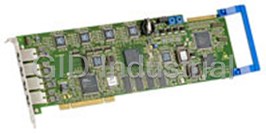
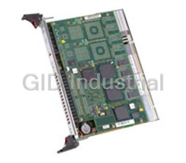
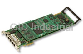
DM/V1200-4E1 DM/V1200-4E1
SPCI4 SPCI4
Figure 1. Sample System ConŢguration
• SS7 code Ţle for SPCI4 (ss7.dc3) V1.13 (or
Introduction
greater)
This application note describes the installation,
®
• Dialogic System Release 6.1 for Linux Service
conŢguration, and run-time operation of two computer
®
Update 268 (or greater)
telephony systems that combine a Dialogic Signaling
®
Board and a Dialogic DM3 Media Board.
®
Windows Operating System
®
These systems will be connected back-to-back using
• Microsoft Windows XP
crossover cables. The gc_basic_call_model demo
® ®
• Dialogic SS7 Development Package for Windows
®
will show how the Dialogic Global Call API library
V5.02 (or greater)
facilitates the development of SS7 telephony applications
• SS7 code Ţle for SPCI4 (SS7.DC3) V1.13 (or
running on top of the ISDN User Part (ISUP) signaling
greater)
protocol.
® ®
• Dialogic System Release 6.0 PCI for Windows
System Description
Service Update 166 (or greater)
In this application note, System A runs Red Hat
Notes:
®
Enterprise Linux v3 and System B runs Windows XP;
®
1. Dialogic Signaling Distributed Architecture
however, readers are free to use the same operating system
(SigDiA) software can be downloaded from
on both System A and System B (see Figure 1). Since the
http://www.dialogic.com/support/helpweb/
conŢguration Ţles given in the appendices are operating
signaling/default.htm
system independent, this should not cause any problems.
®
2. More information about Dialogic System Releases
Hardware Requirements
and Service Updates can be found on
• 2 PCs with Pentium III processors, 512 MB RAM
http://resource.dialogic.com/telecom/support/
®
• 2 Dialogic SPCI4 SS7 Interface Boards with ISUP or
releases/serviceUpdates/index.htm
ISUP-L license buttons
® ®
®
• 2 Dialogic DM/V1200-4E1 Voice Boards (Dialogic
Step 1 – Installing the Dialogic Software
®
Voice Boards, Dialogic DM/V-A Media Boards or
Linux Operating System
®
Dialogic DM/V-B Media Boards in PCI)
®
Refer to the Dialogic System Release 6.1 for Linux
• 2 H.100 CT Bus cables
Software Installation Guide (http://www.dialogic.com/
• 2 crossover E-1 cables
manuals/sr61lin/release_install.pdf) for instructions on
®
how to install the Dialogic System Release software.
Software Requirements
®
Note that you select “Dialogic DMV/DMN/DMT” and
Linux Operating System
the Global Call SS7 Support Software packages at the
• Red Hat Enterprise Linux V3 Update 4
installation menu.
®
• Dialogic SS7 Development Package for Linux V5.05
(or greater)
2
®
Creating SS7 Circuit-Switched Applications using Dialogic Global Call API Application Note
®
1. When the Dialogic System Release Software is successfully installed, start the config.sh script to copy and load
®
the DM3 driver Ţles. When this process completes, the Dialogic DM3 Media Board should be detected and you
should be prompted with this menu:
Dialogic(R) Configuration Manager - Main Screen
___________________________________________________________________________________
1) Dialogic(R)) DM3 Board Summary
2) Dialogic(R) Board Summary (NO BOARDS)
3) Dialogic(R) IPT Board Summary
4) TDM Bus Settings
___________________________________________________________________________________
(s to save, x to save & quit, q to quit) the configuration
? for help and ! for navigation help
You can only configure one board at a time. Enter the number associated
with the product category of the board you want to configure :1
2. Select item 1 to get the list of DM3 Media Boards that are detected on your system:
Dialogic (R) DM3 Board Summary
_______________________________________________________________________________
You must configure or disable each board shown. After a board is
configured, a valid PCD file name is displayed in the PCD File Name
column.
________________________________________________________________________________
Thumb Board Log PCD
Wheel Status Model ID File Name
_______________________________________________________________________________
0) C DM/V1200-4E1 1 NOT_SET
________________________________________________________________________________
(s to save, x to save & quit, q to quit) the configuration
p to return to Dialogic(R) Configuration Manager - Main Screen
? for help and ! for navigation help
Enter the Thumb Wheel of the board to configure: 0
3. Enter the Thumb Wheel number of the board you want to conŢgure (0 in this case).
Modify Board Settings
_______________________________________________________________________________
These are the current settings for the board selected:
Physical Slot...... : 0
Model Name......... : DM/V1200-4E1
Logical ID......... : 1
Board Status....... : Configured
PCD File Name...... : NOT_SET
CONFIG File Name... : NOT_SET
________________________________________________________________________________
The following items can be modified:
1) Specify the PCD File
2) Trunk Configuration
3) Protocol Development Kit (PDK) Configuration (NOT APPLICABLE)
4) Modify NIC Configuration (NOT APPLICABLE)
5) Copy Configuration From Board
6) Advanced Board Settings
_______________________________________________________________________________
(s to save, x to save & quit, q to quit) the configuration
p to return to Dialogic(R) DM3 Board Summary
? for help and ! for navigation help
Enter the number of the item to modify: 1
3
®
Application Note Creating SS7 Circuit-Switched Applications using Dialogic Global Call API
4. Select item number 1 (Specify the PCD File) and you should be prompted with a list of available media loads for the
board you are using.
Specify the PCD File
_______________________________________________________________________________
A Product Configuration Description (PCD) file must be selected to
configure your board. The corresponding CONFIG file will be automatically
selected.
The following PCD files are valid for your board:
1) ml1_qs_dass2.pcd
2) ml1_qs_dpnss.pcd
3) qs_isdn_net5.pcd
4) ml1_qs_net5.pcd
5) qs_isdn_qsige1.pcd
6) ml1_qs_qsige1.pcd
7) qs_r2mf.pcd
8) ml1_qs_r2mf.pcd
9) ml1_qs_ts16.pcd
_______________________________________________________________________________
* is current setting
(s to save, x to save & quit, q to quit) the configuration
p to return to Modify Board Settings
? for help and ! for navigation help
Enter the number corresponding to the PCD file you want to select: 1
5. Select a clear channel media load, such as:
®
• ml1_qs_ts16.pcd for a regular Dialogic DM/V1200-4E1 Media Board
®
• ml2_qsa_ts16.pcd for a Dialogic DM/V1200A-4E1 Media Board
®
Note: When using a Dialogic DM/V-B Media Board, select Trunk ConŢguration (option 2 in the menu below) and
assign E1CC on your E1 trunks.
Modify Board Settings
_______________________________________________________________________________
These are the current settings for the board selected:
Physical Slot...... : 4
Model Name......... : DMV1200BTEP
Logical ID......... : 2
Board Status....... : Configured
PCD File Name...... : qsb_default.pcd
CONFIG File Name... : qsb_default.config
____________________________________________________________________________________________
_The following items can be modified:
1) Specify the PCD File
2) Trunk Configuration
3) Protocol Development Kit (PDK) Configuration (NOT APPLICABLE)
4) Modify NIC Configuration (NOT APPLICABLE)
5) Copy Configuration From Board
6) Advanced Board Settings
________________________________________________________________________________
_
(s to save, x to save & quit, q to quit) the configuration
p to return to Dialogic(R) DM3 Board Summary
? for help and ! for navigation help
Enter the number of the item to modify: 1
®
6. From the Dialogic ConŢguration Manager - Main Screen, type the number 4 and press Enter to select the TDM Bus
Settings option.
7. Select the “” menu (item number 2 in the TDM Bus Settings menu) and make sure that your Dialogic DM/V board
®
is set as “Secondary Master Board” (item number 2), because the Dialogic SS7 board is to be the primary CT Bus
clock master.
4
®
Creating SS7 Circuit-Switched Applications using Dialogic Global Call API Application Note
Figure 2. Forcing a Hardware Detection
® ®
Windows Operating System • Demos — Installs the sample programs for Dialogic
® boards and, among others, the
Refer to the Dialogic System Release 6.0 PCI for Windows
gc_basic_call_model application, which will
Software Installation Guide
be used to make and receive calls between the two
(http://www.dialogic.com/manuals/sr60winpci/release_
systems.
install.pdf) for installation instructions.
®
Once the Dialogic System Release Software has been
1. When the “Select Features” window appears during
installed and the system has been rebooted, do the
installation, check these options:
following:
• Development Package — Allows for recompiling the
®
2. Open up the Dialogic ConŢguration Manager
application, if it is needed.
® 3. Right click on the DM3 device and select “Restore
• Core Runtime Package — Installs Dialogic board
Device Default” to force a re-detection of your
drivers, Ţrmware, and parameter Ţles.
®
Dialogic hardware, as shown in Figure 2.
5
®
Application Note Creating SS7 Circuit-Switched Applications using Dialogic Global Call API
Figure 3. Selecting a Clear Channel Media Load
4. Select a clear channel media load (for example, 3. Change the parameter value to 6 to conŢgure the
ml1_qs_ts16.pcd for a regular DM/V1200-4E1), as corresponding trunk in clear channel mode:
shown in Figure 3. [lineAdmin.1]
…
SetParm=0x1602,6 ! SignalingType
Locating the Appropriate Clear Channel Media
(CAS=4, CCS=5, Clear=6)
Load
…
If you cannot Ţnd an appropriate clear channel media
4. Repeat this operation for the other trunks you want
®
load for your Dialogic DM3 Media Board (for example,
to set in clear channel mode ([lineAdmin.2],
®
for a Dialogic DM/V960-4T1 Voice Board or for a
[lineAdmin.3], etc.)
®
Dialogic DM/IP Board), then manually edit the corre-
®
5. For Windows and Linux operating systems, the
sponding *.config Ţle in order to conŢgure the E-1 or
FCD Ţle is automatically created when the PCD Ţle
T-1 trunk in clear channel mode as follows:
and modiŢed CONFIG Ţle are downloaded to the
1. Identify the *.config Ţle that corresponds to the
board.
media load you have chosen for your DM3 Media
®
6. Re-start the Dialogic Service, and verify that there
Board (for example, ml1_qs_cas.config) and
are now 24 T-1 time slots or 31 E-1 time slots on the
open it in a text editor.
clear channel trunks, using “Devmapdump”:
2. Search for the Ţrst occurrence of the 0x1602
c:\Program Files\Dialogic\bin\
parameter:
Devmapdump > a.txt notepad a.txt
[lineAdmin.1]
…
SetParm=0x1602,4 ! SignalingType
(CAS=4, CCS=5, Clear=6)
…
6
®
Creating SS7 Circuit-Switched Applications using Dialogic Global Call API Application Note
®
Windows Operating System
Step 2 – Installing the Dialogic® SS7
®
Development Package
The Dialogic SS7 Development Package for Windows
®
has an Install Shield script that copies the Ţle and drivers
1. Download the Dialogic Signaling Distributed
to the appropriate directories. More information can be
Architecture (SigDiA) software components from the
found in Section 2.1 of the SS7 Boards Programmer’s
Dialogic web site. The download sections discussed
Manual for SPCI2S, SPCI4 and CPM8 (see the For More
in this application note can be found at
Information section).
http://www.dialogic.com/support/helpweb/signal-
ing/default.htm.
1. The SPCI device driver must be manually registered
to the system using the following command:
2. Go to the Product SpeciŢc on the web page and in
Section 2.7 download the SS7 Binary (code Ţle) for c:\> net start septel
® ®
Dialogic SPCI2S SS7 Interface Board and Dialogic
2. Once you have done this, open up the Windows
SPCI4 SS7 Interface Board. Keep the code Ţle
Device Manager.
(SS7.DC3) in a directory on your system (usually
the “Septel” directory for simplicity). On a Linux 3. Make sure to turn on the Show Hidden devices
system, rename SS7.DC3 to ss7.dc3. option in the View menu. You should now be able to
see the Septel device under the Non-Plug and Play
3. Go to the Generic Information section on the web
Drivers.
®
page and, in Section 3.1, download the Dialogic
®
SS7 Development Package for Windows or the 4. Double-click on the Septel device, go to the Driver
Dialogic SS7 Development Package for Linux. tab, and change the startup mode to automatic.
Linux Operating System
Step 3 – Configuring the Dialogic®
1. For Linux, the Dialogic SS7 Development Package is
Signaling Distributed Architecture
a compressed tar Ţle. Manually uncompress and
Software (system.txt and config.txt)
extract the contents of this Ţle (using the tar utility)
®
Before conŢguring the Dialogic SS7 board and protocol
into a directory you have previously created.
stack, an understanding of the underlying SS7 concepts,
2. Before attempting to load the SPCI driver module,
such as link, link set, point codes, routes, and speciŢcally
compile the object Ţle from the driver source code
the Message Transfer Part (MTP) layers and the ISDN
using the build_spci_cpm.sh script Ţle. This
User Part (ISUP) is fundamental. If you are unfamiliar
build script assumes a suitable environment for build-
with those concepts, you can review the SS7 tutorial on
ing Kernel modules is available. This must include
the Dialogic web site at http://www.dialogic.com/
the appropriate kernel include Ţles found at:
support/helpweb/signaling/tutorial/ss7.htm. For more
/usr/src/linux-`uname -r`/include (for example,
information about the SS7 architecture, read ISDN &
/usr/src/linux-2.4.7-10/include). If these are not
SS7 – Architectures for Digital Signaling Networks [Black]
found, the build will fail. Following that, the
(see the References section.)
install_spci_cpm.sh script installs the device
Two conŢguration Ţles are used when setting up the
driver, automatically allocates a major device number,
®
software for a Dialogic Signaling Board: system.txt
and creates the four appropriate device nodes.
and config.txt. Figure 4 illustrates the protocols to
Note: ‘install_spci_cpm.sh’ dynamically loads the driver
be conŢgured.
module into the kernel. The module will remain loaded
as long as the PC is not rebooted. After a system reboot,
you will have to re-load the module using the insmod
utility.
7
®
Application Note Creating SS7 Circuit-Switched Applications using Dialogic Global Call API
Figure 4. SS7 Protocol Stack
Software Environment Programmer’s Manual
system.txt
(http://www.dialogic.com/support/helpweb/signaling/soft-
The system.txt Ţle speciŢes how the SigDiA software
ware3.htm).
environment is set up. This software environment is
commonly referred to as the GCTLOAD environment.
Two working system.txt Ţles (one for Linux, one for
®
Windows ) are included in Appendices A and D,
You can think of the operation of this SigDiA software as
respectively, for this cross conŢguration. Manually copy
if each protocol layer is an independent module. Each
them into the directory where you have installed the
protocol module can run either on the host CPU or on
®
® Dialogic SS7 Development Package.
the Dialogic SS7 signaling board, except MTP1 and
MTP2, which must always run on the SS7 board.
A review of the three major sections of the system.txt Ţle
Protocol modules use inter-process communication
follows:
mechanisms to exchange messages with each other.
LOCAL
GCTLOAD modules are identiŢed with a module ID. The
The LOCAL commands assign module IDs for the
module ID uniquely identiŢes protocol modules in the
modules that will run on the host CPU. The host
GCTLOAD environment. Any piece of software (for
machine is the computer where the application is
example, the user application) that directly communicates
running. DeŢning modules in this section also creates
with the SS7 protocol modules is also considered a
queues for incoming messages.
GCTLOAD module and must also be assigned its own
module ID. You can learn more about Dialogic SS7
GCTLOAD software environment in the SS7 Protocols
8
®
Creating SS7 Circuit-Switched Applications using Dialogic Global Call API Application Note
Our system.txt will include the following LOCAL commands:
LOCAL 0x20 * Module ID for SSD
LOCAL 0xcf * Module ID for s7_mgt
LOCAL 0xef * Module ID for s7_log
LOCAL 0x4d * Module ID for the GC/SS7 service/daemon
• SSD (System Seven Dispatcher) — Special host module that is responsible for relaying messages from the host to the
board
• S7_mgt — ConŢguration utility that reads the config.txt Ţle and conŢgures the board and protocol modules
(see config.txt; and Appendix B for Linux, Appendix E for Windows)
• S7_log — General-purpose logger; use to analyze system run-time behavior and troubleshoot problems
®
• GC/SS7 service daemon — Server side of the Dialogic Global Call Software for SS7 client/server architecture,
responsible for receiving and sending SS7 messages from and to the ISUP protocol module
REDIRECT
The REDIRECT section redirects messages sent to one module ID to an alternative module. For example, if you
REDIRECT messages sent to ISUP (0x23) to SSD (0x20), these messages will be sent to the board via the SSD process.
This would be used where protocol modules are running on the board.
Since we are running MTP2, MTP3, and ISUP on the signaling board, we REDIRECT the messages for these layers.
REDIRECT 0x71 0x20 * MTP2 messages redirected to SS7 card
REDIRECT 0x22 0x20 * MTP2 messages redirected to SS7 card
REDIRECT 0x23 0x20 * ISUP messages redirected to SS7 card
FORK_PROCESS
The FORK_PROCESS section actually executes programs, such as protocol modules running on the host or management
tools (for example, s7_mgt). In the conŢguration described here, no protocols are running on the host, so only manage-
ment tools will be forked (for example, s7_log, s7_mgt).
config.txt
The config.txt Ţle is used for protocol conŢguration. It contains conŢguration commands for the MTP and ISUP
protocols. s7_mgt reads the contents of this Ţle and translates the conŢguration commands into management messages
that are sent to the different protocol modules.
®
Two working config.txt Ţles (one for Linux, one for Windows ) are included in Appendices B and E for this cross
conŢguration. Manually copy them into the directory where you have installed the Dialogic SS7 Development Package.
For a description of the protocol conŢguration commands for the SPCI4 and SPCI2S products, refer to Appendix A of the
SS7 Programmer’s Manual for SPCI2S, SPCI4 and CPM8 (see the For More Information section).
9
®
Application Note Creating SS7 Circuit-Switched Applications using Dialogic Global Call API
Physical Configuration
The SEPTELPCI_BOARD command deŢnes the settings of the board itself. It allows deŢning the clock source for the
board, and identiŢes what protocol modules are running on the board.
* <ţags>
SEPTELPCI_BOARD 0 0x0043 ss7.dc3 ISUP
<ţags> - Possible values
CTbus Slave 0x00C2
CTbus Master – clock derived from one of the SS7 card line interfaces 0x0043
CTbus Master – clock derived from SS7 card internal oscillator 0x0042
In this case, set on System A to 0x0042 and on System B to 0x0043, so that System B synchronizes on the
clock generated by System A.
The LIU_CONFIG command conŢgures the operating parameters for an E-1/T-1 trunk interface. These parameters
include the line encoding, the frame format, and whether Cyclical Redundancy Check (CRC) is enabled or not.
*
LIU_CONFIG 0 0 5 1 1 1
MTP Configuration
The three types of point codes to be conŢgured are as follows:
• Local Point Code (LPC) — The SS7 address of the signaling point to be conŢgured. Assign Point Code 1 to System A
and Point Code 2 to System B.
• Adjacent Point Code (APC) — The SS7 address of the adjacent signaling point; this is the node to which the system
has physical connection(s). For System A, the APC is Point Code 2. For System B, it is Point Code 1.
• Destination Point Code (DPC) — The SS7 address of the remote signaling point; this is the node the system has to
exchange SS7 messages with. In this case (back-to-back conŢguration), the APC is also the DPC.
MTP_CONFIG is the main conŢguration command for the MTP module. The Ţrst two parameters are not used and can be
left to 0. The Ţeld allows conŢguring the variant being used (ITU or ANSI).
• For ITU operation, bits can be set to 0.
• For ANSI operation, bits 8, 9, 10, and 11 must be set to 1, leading to a value of 0x00000f00.
*
MTP_CONFIG 0 0 0x00000000
The MTP_LINKSET command is used for the conŢguration of a link set to an adjacent signaling point.
*
MTP_LINKSET 0 2 1 0x0000 1 0x8
The parameter is a 4-bit value made up (DCBA) with:
D C Network type
0 0 International network
0 1 International spare
1 0 National network
1 1 National spare
B A Priority value
0 0 0
0 1 1
1 0 2
1 1 3
10
®
Creating SS7 Circuit-Switched Applications using Dialogic Global Call API Application Note
In ITU, the most common SSF value for MTP3 messages is 0x8. In ANSI operation, the most common SSF value for
MTP3 is 0xb.
The MTP_LINK command is used to deŢne the links within every link set.
*


 Manufacturers


What they say about us
FANTASTIC RESOURCE
One of our top priorities is maintaining our business with precision, and we are constantly looking for affiliates that can help us achieve our goal. With the aid of GID Industrial, our obsolete product management has never been more efficient. They have been a great resource to our company, and have quickly become a go-to supplier on our list!
Bucher Emhart Glass
EXCELLENT SERVICE
With our strict fundamentals and high expectations, we were surprised when we came across GID Industrial and their competitive pricing. When we approached them with our issue, they were incredibly confident in being able to provide us with a seamless solution at the best price for us. GID Industrial quickly understood our needs and provided us with excellent service, as well as fully tested product to ensure what we received would be the right fit for our company.
Fuji
HARD TO FIND A BETTER PROVIDER
Our company provides services to aid in the manufacture of technological products, such as semiconductors and flat panel displays, and often searching for distributors of obsolete product we require can waste time and money. Finding GID Industrial proved to be a great asset to our company, with cost effective solutions and superior knowledge on all of their materials, it’d be hard to find a better provider of obsolete or hard to find products.
Applied Materials
CONSISTENTLY DELIVERS QUALITY SOLUTIONS
Over the years, the equipment used in our company becomes discontinued, but they’re still of great use to us and our customers. Once these products are no longer available through the manufacturer, finding a reliable, quick supplier is a necessity, and luckily for us, GID Industrial has provided the most trustworthy, quality solutions to our obsolete component needs.
Nidec Vamco
TERRIFIC RESOURCE
This company has been a terrific help to us (I work for Trican Well Service) in sourcing the Micron Ram Memory we needed for our Siemens computers. Great service! And great pricing! I know when the product is shipping and when it will arrive, all the way through the ordering process.
Trican Well Service
GO TO SOURCE
When I can't find an obsolete part, I first call GID and they'll come up with my parts every time. Great customer service and follow up as well. Scott emails me from time to time to touch base and see if we're having trouble finding something.....which is often with our 25 yr old equipment.
ConAgra Foods