

 Manufacturers
DATALOGIC 930153129

Description
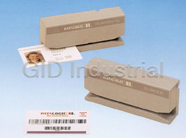
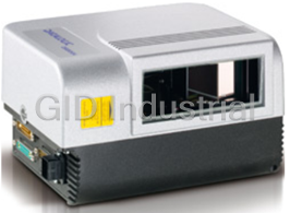
Datalogic DS2100A-1210 Barcode scanner - desktop - 800 scan / sec - decoded - RS-232/485
Part Number
930153129
Price
Request Quote
Manufacturer
DATALOGIC
Lead Time
Request Quote
Category
PRODUCTS - 9
Specifications
Compatibility
PC
Connectivity Technology
Wired
Decode Capability
Pharmacode 39, EAN/JAN, Code 93, Code 39, UCC/EAN-128, Codabar, Code 128, Code 2 of 5, UPC
Dimensions (WxDxH)
8.4 cm x 1.6 cm x 6.8 cm
Humidity Range Operating
0 - 90%
Interfaces
1 x serial - RS-232/485 - 25 pin D-Sub (DB-25)
Scan Element Type
Visible laser diode
Scan Speed
800 scan / sec
Weight
300 g
Features
- 8.4 cm x 1.6 cm x 6.8 cm
- Visible laser diode
Datasheet

Extracted Text
DS2100A QUICK GUIDE DS2100A General View: Laser Safety: The scanner is classified as a Class 2 laser 1 product according to EN 60825-1 regulations 2 3 and as a Class II laser product according to 4 CDRH regulations. 5 Disconnect the power supply when opening the device during maintenance or installation to avoid exposure to hazardous laser light. There is a safety device which allows the laser to be switched on only if the motor is rotating above the threshold for its correct scanning speed. The laser beam can be switched off through a software command (see also the WinHost Help 6 On Line). LASER LIGHT DO NOT STARE INTO BEAM CLASS 2 LASER PRODUCT MAX. OUTPUT RADIATION 1 mW EMITTED WAVE LENGTH 630~680 nm TO EN 60825-1:2001 7 CAUTION-CLASS 3B LASER LIGHT N2468 8 WHEN OPEN AVOID EXPOSURE TO BEAM This product conforms to the applicable Figure A R requirements of 21CFR1040 at the date 218441 of manufacture. CUS 1 Mounting Holes 5 Power On / Data TX LED Laser On LED Warning and Device Class Labels 2 6 Good Read LED Accessory Mounting Holes 3 7 Warning and Device Class Labels External Trigger LED Laser Beam Output Window 4 8 The laser diode used in this device is classified as a class 3B laser product according to EN 60825-1 regulations and as a For further details on product installation, see the complete Reference Manual on the installation CD-ROM. Class IIIb laser product according to CDRH regulations. As it is not possible to apply a DS2100A can be configured through the WinHost classification label on the laser diode used in Windows-based software program available on the this device, the following label is reproduced installation CD-ROM. below. For configuration it is necessary to create a cable connecting the scanner to the PC as indicated in the “How To Build A Simple Interface Test Cable” section of LASER LIGHT this guide, otherwise you can use the C-Box 100. AVOID EXPOSURE TO BEAM CLASS 3B LASER PRODUCT MAX. OUTPUT RADIATION 35 mW Power Supply: EMITTED WAVE LENGTH 630~680 nm TO EN 60825-1 (2001) - This product is intended to be installed by Qualified Personnel only. - All Models: Laser Diode Class Label This accessory device is intended to be supplied by a UL Listed or CSA Certified Power Unit with «Class 2» or LPS Any violation of the optic parts in particular power source which supplies power directly to the scanner can cause radiation up to the maximum level via the 25-pin connector. of the laser diode (35 mW at 630 to 680 nm). WEEE Compliance: DS2100A QUICK GUIDE Model Description: DS2100A - X X X X Optical Resolution Communication Interface Optic Version Performance 1 = Standard resolution 2= RS232/RS485main + RS232 aux 0 = Linear 0 = Standard 2 = High resolution 1 = Raster R1 4 = Testarossa ™ Reading Performance: Version Reading Distance Max Code Resolution Speed mm (mils) scans/s 1XX0 40 mm (1.6 in) - 300 mm (11.8 in) on 0.50 mm (20 mils) codes 0.20 (8) 500 to 800 1XX4 50 mm (1.8 in) - 310 mm (11.8 in) on 0.50 mm (20 mils) codes 0.20 (8) 800 to 1000 2XX0 30 mm (1.2 in) - 90 mm (3.5 in) on 0.30 mm (12 mils) codes 0.15 (6) 500 to 800 2XX4 45 mm (1.8 in) - 100 mm (3.9 in) on 0.20 mm (8 mils) codes 0.12 (5) 800 to 1000 Technical Features: ELECTRICAL FEATURES SOFTWARE FEATURES Power Supply 10 –30 Vdc Readable Codes Power Consumption Model XXX0: 3W * EAN/UPC (including Add-on 2 and Add-on 5) Model XXX4: 5W Code 39 * Main Serial Interface Programmable: 2/5 Interleaved RS232; * Code 128 * RS485 Full-Duplex/Half- EAN 128 * Duplex; Codabar * Auxiliary Interface RS232 Code 93 * * = ACB readable Baudrates 150 to 115200 ISBT 128 Inputs Pharmacode External Trigger (optocoupled NPN or PNP) Headers and Up to four header and four Voltage max. 30 Vdc Terminators terminator characters Current Consumption 25 mA Operating Modes On-Line, Automatic, max. Serial-On-Line, Test Outputs) Configuration Modes Through menus using: OUT1, OUT2 (optocoupled) WinHost utility Host Mode (commands from V max. 40 Vdc one of the serial ports) CE Collector Current 40 mA continuous; Code Selection Up to six different codes max. 130 mA pulsed during one reading phase V Saturation 1V at 10 mA max. Decoding Safety Can enable multiple good CE Power Dissipation 90 mW at 40 °C reads of the same code max. (Ambient temp.) Special Functions ACB (Advanced Code Builder) Motor Off OPTICAL FEATURES Parameter Storage Non-volatile internal EEPROM Light Source semiconductor laser diode ENVIRONMENTAL FEATURES Wavelength In the range 630 to 680 nm Operating 0° to +40 °C (+32° to +104 °F) Safety Class Temperature Class 2 - EN 60825-1; CDRH Storage -20° to +70 °C (-4° to +158 °F) USER INTERFACE Temperature LED Indicators Laser ON, Good Read, Humidity max 90% non condensing External Trigger, Vibration Resistance 14 mm @ 2 to 10 Hz; Data TX / Power ON IEC 68-2-6 test FC 1.5 mm @ 13 to 55 Hz; 2 G @ 70 to 200 Hz; PHYSICAL FEATURES 2 hours on each axis Dimensions 68x83.6x34 mm (2.7x3.29x1.3 in) Shock Resistance 30 G; Weight 330 g. (11.64 oz) IEC 68-2-27 test EA 11 ms; 3 shocks on each axis Protection Class IP65 2 DS2100A QUICK GUIDE Accessories: Name Description Part Number GFC-2100 90° Reading Device 93A201000 GFC-2000 75° Reading Device 93A201080 OM2000 Oscillating Mirror 93A251031 INT-30 (for C-Box 100) 20 mA Current Loop Interface Board 93A151022 C-BOX 100/200 Connection Box 93ACC1510,93ACC1520 C-BOX 300/310 Connection Box Profibus 93A301000, 93A301030 C-BOX 400/410 Connection Box DeviceNet 93A301010, 93A301040 MEP-542/543 Photocell Kit NPN/PNP 93ACC1727, 93ACC1728 Electrical Connections: DS2100A is equipped with a cable terminated by a 25-pin female D-sub connector for connection to the power supply and input/output signals. You can bring system cables directly to the 25-pin connector or you can connect the scanner directly to one of the various C-Box models and bring system wiring to it (see the relative C-Box Installation Manual). Do not connect GND and SGND to different (external) ground references. GND and SGND are internally connected through filtering circuitry which can be permanently damaged if subjected to voltage drops over 0.8 Vdc. CAUTION The details of the connector pins are indicated in the following table: 25-pin D-sub female connector pinout Pin Name Function 13 VS Power supply input voltage + 25 GND Power supply input voltage - 1 CHASSIS Chassis Ground 9 VS External Trigger supply voltage + 18 EXT TRIG+ External Trigger + 19 EXT TRIG- External Trigger - 8 OUT1 + Output 1 + 11 OUT2 + Output 2 + 12, 22 OUT REF Output reference 20 RXAUX Auxiliary RS232 21 TXAUX Auxiliary RS232 25-pin female connector 23 CTSAUX Auxiliary handshake RS232 24 RTSAUX Auxiliary handshake RS232 6, 10, 14, NC Not Connected 15, 16, 17 RS485 RS485 Pin RS232 Full-Duplex Half-Duplex 2 TX232 TX485+ RTX485+ 3 RX232 RX485+ 4 RTS232 TX485- RTX485- 5 CTS232 RX485- 7 SGND SGND SGND 3 4.2 R 40 4.2 n° 2 DS2100A QUICK GUIDE Mechanical Installation: 84 14.7 23.3* 3.31 0.92 0.58 9 M 4 n° 4 14 4.2 4 0.55 0.16 90° DS2100A 20° 23 mm mm inch * The quote refers to the scan line Input/Output Connections: INPUT NPN INPUT NPN MEP-543 DS2100A MEP-543 Connector DS2100A Vext 30 Vdc max. EXTERNAL TRIGGER VS 9 (brown) + 5V 18 + 5V EXT TRIG+ EXT TRIG+ V 18 (white) 2 1 19 EXT TRIG- EXT TRIG- 19 Signal 3 4 25 GND (blue) Input NPN command using external power Input NPN command using MEP-543 Photocell OUTPUT DS2100A EXTERNAL TRIGGER Vext 40 Vdc max. DS2100A USER INTERFACE VS 9 V + 5V EXT TRIG+ 8/11 18 C + OUT REF EXT TRIG- 12/22 19 Signal E 25 GND Ground Output open collector connections Input NPN command using DS2100A power INPUT PNP V max = 40 Vdc DS2100A Vext 30 Vdc max. EXTERNAL TRIGGER CE I max = 40 mA continuous V + 5V Signal 18 EXT TRIG+ 19 EXT TRIG- Ground Input PNP command using external power DS2100A EXTERNAL TRIGGER 9 VS V + 5V Signal EXT TRIG+ 18 EXT TRIG- 19 25 GND Ground Input PNP command using DS2100A power 4 68 2.68 46 1.81 10.3 40 0.41 1.57 32.7 1.29 10.3 40 1.57 0.41 73 2.5 42 7.8 30 13.8 2.5 17.5 1 x 45° n° 2 DS2100A QUICK GUIDE Connectivity: RS232 Main Interface Connections RS485 Main Interface Connections RS232 Point-to-point layout RS485 Point-to-point layout DS2100A D DS S2100 2100A A Terminal Host Terminal Terminal Hos Host t c Main Serial Interface (RS232) c Main Serial Interface (RS485 Full Duplex) dAuxiliary Serial Interface (Local Echo) (RS232) dAuxiliary Serial Interface (Local Echo) (RS232) eExternal Trigger (for On-Line Mode) eExternal Trigger (for On-Line Mode) Pass-through layout Multiplexer layout DS2100A DS2100A Host Host MX4000 c Main Serial Interface (RS232) c Main Serial Interface (RS485 Half-Duplex) dAuxiliary Serial Interface (RS232) dAuxiliary Serial Interface (Local Echo) (RS232) eExternal Trigger (for On-Line Mode) eExternal Trigger (for On-Line Mode) RS232 Master/slave layout RS485 Master/slave layout Host DS2100A Slave DS2100A Slave DS2100A Slave DS2100A Master DS2100A Slave DS2400A Host Master c Main Serial Interface (Slaves RS232 only) c Auxiliary Serial Interface (RS232) dAuxiliary Serial Interface (RS232) d Main Serial Interface (RS485 Half-Duplex) eExternal Trigger (for On-Line Mode) eExternal Trigger 5 DS2100A QUICK GUIDE Reading Diagrams: DS2100A-1200 (Standard Resolution, 500 scans/s) (in) 0 121 3 45 6 7 8 9 0 11 12 (mm) 0 20 40 60 80 100120140160180200220 240 260 280 300 5 120 4 100 80 3 CONDITIONS 60 2 Optic Version = Linear 40 Code = Interleaved 2/5 or Code 39 0.35 mm 1 0.20 mm 0.30 mm (14 mils) ≥ 0.50 mm PCS = 0.90 20 (8 mils) (12 mils) (20 mils) Pitch angle = 0° Skew angle = 15° 0 0 Tilt angle = 0° *Code Reading Condition = Standard 20 1 40 2 * Parameter selectable in Winhost 60 3 80 100 4 120 5 (mm) (in) DS2100A-1200 Reading Distance vs Scanning Speed Distance 01 2 10 3 4 5 6 7 8 9 11 12 (in) (mm) 0 20 40 60 80 100120140160180200220 240260 280 300 0.50 mm 0.35 mm 0.30 mm 0.20 mm 500 scans/s Code 800 scans/s Resolution 6 DS2100A QUICK GUIDE DS2100A-2200 (High resolution, 500 scans/s) 0124 3 5 (in) 0 10 50 60 100 120 (mm) 20 30 40 70 80 90 110 130 60 2 50 40 30 CONDITIONS ≥ 0.30 mm 1 (12 mils) Optic Version = Linear 20 Code = Interleaved 2/5 or Code 39 PCS = 0.90 0.15 mm 10 Pitch angle = 0° (6 mils) Skew angle = 15° 0 0 Tilt angle = 0° *Code Reading Condition = Standard 10 * Parameter selectable in Winhost 20 1 0.20 mm 30 (8 mils) 40 50 2 60 (mm) (in) DS2100A-2200 Reading Distance vs Scanning Speed Distance (in) 0 1 24 3 5 (m m ) 0 10 20 30 40 50 60 70 80 90 100 110 120 130 0.30 m m 0.20 m m 0.15 m m 500 scans/s 800 scans/s Code Resolution 7 DS2100A QUICK GUIDE DS2100A-1204 Testarossa™ (Standard resolution, 1000 scan/s) 0 121 3 45 6 7 8 9 0 11 12 (in) 0 20 40 60 80 100120140160180200220 240 260 280 300 (mm) 5 120 4 100 CONDITIONS 80 3 60 Optic Version = Linear Code = Interleaved 2/5 or Code 39 2 40 PCS = 0.90 Pitch angle = 0° 1 20 Skew angle = 15° 0.15 mm (6 mils) Tilt angle = 0° ≥ 0.50 mm 0.30 mm 0 0 *Code Resolution: (20 mils) (12 mils) 0.20 mm High - for 0.30 mm (12 mils) (8 mils) 20 1 codes and smaller Standard - for 0.50 mm (20 mils) 40 codes and greater 2 *Code Reading Condition = Standard 60 3 80 * Parameter selectable in Winhost 100 4 120 5 (mm) (in) DS2100A-2204 Testarossa™ - (High Resolution, 1000 scans/s) (in) 0124 3 5 (mm) 0 10 20 30 40 50 60 70 80 90 100 110 120 130 60 2 50 CONDITIONS 40 Optic Version = Linear Code = Interleaved 2/5 or Code 39 30 PCS = 0.90 0.20 mm ≥ 1 Pitch angle = 0° (8 mils) 20 Skew angle = 15° Tilt angle = 0° 0.12 mm 10 (5 mils) *Code Resolution: High - for 0.15 mm (6 mils) codes 0 0 and smaller Standard - for 0.20 mm (8 mils) 10 codes *Code Reading Condition = Standard 20 1 0.15 mm 30 (6 mils) * Parameter selectable in Winhost 40 50 2 60 (mm) (in) 8 DS2100A QUICK GUIDE User Interface: The following table contains the pinout for standard RS232 PC Host interface. For other user interface types please refer to their own manual. RS232 PC-side connections 1 5 1 13 6 9 14 25 9-pin male connector 25-pin male connector Pin Name Pin Name 2 RX 3 RX 3 TX 2 TX 5 GND 7 GND 7 RTS 4 RTS 8 CTS 5 CTS How To Build A Simple Interface Test Cable: The following wiring diagrams show a simple test cable including power, external (push-button) trigger and PC RS232 COM port connections. 25-pin D-sub male 9-pin D-sub female TXAUX 21 2 RX PC 20 RXAUX 3 TX SGND 7 5 GND 13 VS 25 DS2100A GND 9 VS 18 EXT TRIG+ 19 EXT TRIG- Power Supply VS (10 – 30 Vdc) Power GND Trigger Test Cable for DS2100A 9 DATALOGIC S.p.A., Via Candini, 2 40012 - Lippo di Calderara 05 Bologna - Italy dichiara che declares that the déclare que le bescheinigt, daß das Gerät declare que el DS2100A-XXXX Laser Scanner e tutti i suoi modelli and all its models et tous ses modèles und seine modelle y todos sus modelos sono conformi alle Direttive del Consiglio Europeo sottoelencate: are in conformity with the requirements of the European Council Directives listed below: sont conformes aux spécifications des Directives de l'Union Européenne ci-dessous: der nachstehend angeführten Direktiven des Europäischen Rats: cumple con los requisitos de las Directivas del Consejo Europeo, según la lista siguiente: 89/336/EEC EMC Directive e 92/31/EEC, 93/68/EEC emendamenti successivi and further amendments et ses successifs amendements und späteren Abänderungen y succesivas enmiendas Basate sulle legislazioni degli Stati membri in relazione alla compatibilità elettromagnetica ed alla sicurezza dei prodotti. On the approximation of the laws of Member States relating to electromagnetic compatibility and product safety. Basée sur la législation des Etats membres relative à la compatibilité électromagnétique et à la sécurité des produits. Über die Annäherung der Gesetze der Mitgliedsstaaten in bezug auf elektromagnetische Verträglichkeit und Produktsicherheit entsprechen. Basado en la aproximación de las leyes de los Países Miembros respecto a la compatibilidad electromagnética y las Medidas de seguridad relativas al producto. Questa dichiarazione è basata sulla conformità dei prodotti alle norme seguenti: This declaration is based upon compliance of the products to the following standards: Cette déclaration repose sur la conformité des produits aux normes suivantes: Diese Erklärung basiert darauf, daß das Produkt den folgenden Normen entspricht: Esta declaración se basa en el cumplimiento de los productos con las siguientes normas: EN 55022 (Class A ITE), August 1994: LIMITS AND METHODS OF MEASUREMENTS OF RADIO DISTURBANCE Amendment A1 (Class A ITE), October 2000: CHARACTERISTICS OF INFORMATION TECHNOLOGY EQUIPMENT EN 61000-6-2, October 2001: ELECTROMAGNETIC COMPATIBILITY (EMC) PART 6-2: GENERIC STANDARDS - IMMUNITY FOR INDUSTRIAL ENVIRONMENTS Lippo di Calderara, 08/09/2005 Ruggero Cacioppo Quality Assurance Supervisor 821000954 (Rev. D1)
Frequently asked questions
What makes Elite.Parts unique?

What kind of warranty will the 930153129 have?
Which carriers does Elite.Parts work with?
Will Elite.Parts sell to me even though I live outside the USA?
I have a preferred payment method. Will Elite.Parts accept it?
Why buy from GID?

Quality
We are industry veterans who take pride in our work

Protection
Avoid the dangers of risky trading in the gray market

Access
Our network of suppliers is ready and at your disposal

Savings
Maintain legacy systems to prevent costly downtime

Speed
Time is of the essence, and we are respectful of yours
Related Products


Request a Quote

The quote request has been received
Close

Facing challenges or have inquiries? Feel free to contact us!
Call Us +1-469-283-2440
What they say about us
FANTASTIC RESOURCE
One of our top priorities is maintaining our business with precision, and we are constantly looking for affiliates that can help us achieve our goal. With the aid of GID Industrial, our obsolete product management has never been more efficient. They have been a great resource to our company, and have quickly become a go-to supplier on our list!
Bucher Emhart Glass
EXCELLENT SERVICE
With our strict fundamentals and high expectations, we were surprised when we came across GID Industrial and their competitive pricing. When we approached them with our issue, they were incredibly confident in being able to provide us with a seamless solution at the best price for us. GID Industrial quickly understood our needs and provided us with excellent service, as well as fully tested product to ensure what we received would be the right fit for our company.
Fuji
HARD TO FIND A BETTER PROVIDER
Our company provides services to aid in the manufacture of technological products, such as semiconductors and flat panel displays, and often searching for distributors of obsolete product we require can waste time and money. Finding GID Industrial proved to be a great asset to our company, with cost effective solutions and superior knowledge on all of their materials, it’d be hard to find a better provider of obsolete or hard to find products.
Applied Materials
CONSISTENTLY DELIVERS QUALITY SOLUTIONS
Over the years, the equipment used in our company becomes discontinued, but they’re still of great use to us and our customers. Once these products are no longer available through the manufacturer, finding a reliable, quick supplier is a necessity, and luckily for us, GID Industrial has provided the most trustworthy, quality solutions to our obsolete component needs.
Nidec Vamco
TERRIFIC RESOURCE
This company has been a terrific help to us (I work for Trican Well Service) in sourcing the Micron Ram Memory we needed for our Siemens computers. Great service! And great pricing! I know when the product is shipping and when it will arrive, all the way through the ordering process.
Trican Well Service
GO TO SOURCE
When I can't find an obsolete part, I first call GID and they'll come up with my parts every time. Great customer service and follow up as well. Scott emails me from time to time to touch base and see if we're having trouble finding something.....which is often with our 25 yr old equipment.
ConAgra Foods