

 Manufacturers
DATA MODUL NCB410
Description
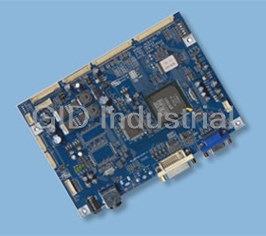
Data Modul NCB410 TFT LCD Monitor Control Board - For LCD/PDP Monitor (PC, DVI, Video) Interface Controller
Part Number
NCB410
Price
Request Quote
Manufacturer
DATA MODUL
Lead Time
Request Quote
Category
PRODUCTS - N
Specifications
LCD Module
SVGA, XGA, WXGA, SXGA
OSD Control
Menu, Left, Right, Up, Down, Source, Power
Resolution
H: 31 ~ 80kHz
Signal Input
Analog RGB, TMDS(DVI). NTSC/PAL
Support
V: 55 ~ 76Hz
Features
- Computer video signals of VGA, SVGA, XGA, WXGA, SXGA and UXGA standard.
- Input Signal Support
- PDP panels of 852x480, 1024x768 and 1366x768 resolutions.
- TFT (active matrix) LCD panels of 1280x768, 1366x768, 1600x1200, 1920x1080 and 1920x1200 resolutions.
- Video signals of NTSC, PAL standard
Datasheet

Extracted Text
For LCD/PDP Monitor (PC, DVI, Video) Interface Controller For 1280x768, 1366x768, 1600x1200, 1920x1080, 1920x1200 Resolutions TFT LCD/PDP DATA SHEET TFT LCD Monitor Control Board NCB410U4-DS-A1 June 2005 1 CONTENT • INTRODUCTION --------------------------------------------- 4 • GENERAL SPECIFICATION --------------------------------------------- 5 • SYSTEM DESIGN --------------------------------------------- 8 • BLOCK DIAGRAM --------------------------------------------- 9 • ASSEMBLY NOTES --------------------------------------------- 10 • CONNECTION & OPERATION --------------------------------------------- 13 • OSD --------------------------------------------- 14 • OSD FUNCTION --------------------------------------------- 16 • CONNECTOR, PINOUT & JUMPER --------------------------------------------- 21 • CONTROLLER DIMENSIONS --------------------------------------------- 28 • APPLICATION NOTES --------------------------------------------- 29 • TROUBLESHOOTING --------------------------------------------- 30 • APPLICABLE GRAPHIC MODE --------------------------------------------- 31 • ACCESSORY --------------------------------------------- 32 • APPENDIX --------------------------------------------- 33 2 Revision History No Data Revision Page 1 A1 Preliminary Release 2 3 INTRODUCTION Designed for LCD monitor and other flat panel display application the NCB410U4 controller provides an auto-input synchronization and easy to sue interface controller for: ► TFT (active matrix) LCD panels of 1280x768, 1366x768, 1600x1200, 1920x1080 and 1920x1200 resolutions. ► PDP panels of 852x480, 1024x768 and 1366x768 resolutions. ► Computer video signals of VGA, SVGA, XGA, WXGA, SXGA and UXGA standard. ► Video signals of NTSC, PAL standard ► Input Signal Support � All VESA standard HOW TO PROCEED ► Ensure that you have all parts & they are correct, refer to: � Connection diagram � Connector reference � Assembly notes ► Check controller switch & jumper settings (errors may damage the panel) ► Prepare the PC & Video ► Connect the parts ► Understand the operation & functions IMPORTANT USAGE NOTE This equipment is for use by developers and integrators. The manufacturer accepts no liability for damage or injury caused by the use of this product. It is the responsibility of the developer, integrators or other users of this product to: � Ensure that all necessary and appropriate safety measures are taken. � Obtain suitable regulatory approvals as may be required. � Check power settings to all component parts before connection. DISCLAIMER There is no implied or expressed warranty regarding this material. 4 GENERAL SPECIFICATION No. Item Description WVGA Panel 8520X480 NCB410WV4 Note 1) XGA Panel 1024X768 NCB410X4 WXGA Panel 1280X768 NCB410W4 1 Model name WXGA Panel 1366X768 NCB410WZ4 UXGA Panel 1600X1200 NCB410U4 HD Panel 1920X1080 NCB410WH4 WUXGA Panel 1920X1200 NCB410WU4 2 LCD Module SVGA, XGA, WXGA, SXGA 3 Signal Input Analog RGB, TMDS(DVI). NTSC/PAL Resolution H: 31 ∼ 80kHz 4 Support V: 55 ∼ 76Hz OSD Control Menu, Left, Right, Up, Down, Source, Power 5 keys 5 Plug & Play VESA DDC 2B Ver1.3 Type: IEC320 MALE 3Line 6 Power Connector Input Connector Supply Power 12Vdc/15Vdc/18Vdc or 25Vdc 7. Voltage Consumption Max Power 18W (Without Back Light Inverter) DSUB 15P(R, G, B Separate H, V Analog Sync) 8 Signal Connector Digital DVI-D(TMDS) TMDS Video MINIDIN-4P(SVHS), RCA(CVBS) Notes 1) Depends On Panel Resolution - WV : WVGA (850X480) - X : XGA (1024X768) - W : WXGA (1280X768) - WZ : WXGA (1366X768) - U : UXGA (1600x1200) - WH : HD 1080i (1920x1080) - WU : WUXGA (1920x1200) 5 ELECTRICAL SPECIFICATION Input characteristic Description Signal Unit Min Typical Max Remarks Power In (24V) Input Vdc 22.8 24.0 25.2 ConsumptioWatt TBD Without INV n Power In (18V) Input Vdc 17.0 18.0 19.0 ConsumptioWatt TBD Without INV n Power In (15V) Vdc 14.75 15.0 15.75 Input ConsumptioWatt TBD Without INV n Power In (12V) Input Vdc 11.4 12.0 12.6 ConsumptioWatt TBD Without INV n RGB Input Analog RGB Vp-p 0 0.7 - Sync Vdc 0 5 5.5 H KHz 31 80 Depends on Mode Frequency V Frequency Hz 55 60 75 DVI Input TMDS mVp-p 450 500 900 NTSC/PAL Y/CVBS Vp-p 0.7 1.0 1.4 C Vp-p 0.6 0.8 1.0 6 Output Characteristics Descriptio Signal Unit Min Typical Max Remarks n Panel Power LCD Power Vdc 17.1 18 18.9 Jumper option (18V) (Representative LCD Power Vdc 14.25 15 15.75 12V) (15V) LCD Power Vdc 11.4 12 12.6 (12V) LCD Vdc 4.75 5 5.25 Jumper option Power(5V) LCD Vdc 3.13 3.3 3.46 Jumper option Power(3.3V) LVDS Interface Differential Vp-p 250 350 450 Different +/- output (mV) Inverter Interface Power out Vdc 22.8 24 25.2 Depends on Power 17.1 18 18.9 Input and Spec. 14.25 15 15.75 11.4 12 12.6 On/Off control V 0 3.3 L=off, H=on Brightness V 3.3 0 Option control 0 4V Option Step 0 100 OSD Value 7 SYSTEM DESIGN A typical LCD based display system utilizing this controller is likely to comprise the following. 1. LCD 6. INVERTER PANEL 7. LCD INTERFACE CABLE J801 LVDS 1CH J802 LCD LVDS 2CH J803 SW101 J703 J713 Internal SMPS JP802 J801 : Jumper for LCD Power J704 J718 Jumper for Panel J715 J727: Jumper for Input Power J701 3. LCD controller Board J702 J718 To RS232 Board JP701 Jumper for Inverter Power 24V or 12V/15V/18V J714 J721 J903 J901 J90 J724 J90 J101 9. DC Power Jack 8. DC Power Jack 11. S-VIDEO 5. OSD KEY 13. ANALOG VGA Input 12. DVI-D 4 10. Composite 8 A typical PDP based display system utilizing this controller is likely to comprise the following. 1. PDP PANEL 2. SMPS 5. LCD INTERFACE CABLE 4. POWER 3. POWER J801 J802 J803 PDP L SW101 J703 J713 JP80 JP801 J704 PDP Power Control J718 Jumper for Panel Type. J715 J727: Jumper for Input J701 6. PDP J702 To RS232 Board JP70 J714 J721 J903 J901 J90 J724 J90 J101 10. S-VIDEO 7. OSD KEY 12. ANALOG 1 8. OSD 9. Composite 9 BLOCK DIAGRAM LVDS RED SCALER GREEN BLUE SYNC (DSUB 15P) CVBS VIDEO SVHS MCU DECODER (RCA, M4P) 2 E PROM DC/DC Inverter POWER Power Control 10 ASSEMBLY NOTES This controller is designed for monitors and custom display projects using TFT (active matrix) LCD panels of 1280x768, 1366x768, 1600x1200, 1920x1080 and 1920x1200 resolutions, PDP panels of 852x480, 1024x768 and 1366x768 resolutions VGA, SVGA, XGA, WXGA, SXGA, WSXGA and UXGA signal input. The following provides some guidelines for installation and preparation of a finished display solution. Preparation: Before preceding it is important to familiarize yourself with the parts making up the system and the various connectors, mounting holes and general layout of the controller. As much as possible connectors have been labeled. Guides to connectors and mounting holes are shown in the following relevant sections. 1. LCD Panel: This controller has LVDS interface logic on the Board for different kind of TFT LCD panel. Due to the different signal timing and electrical characteristics from each LCD panel manufacturer, for selecting LCD interface type and resolution, put jumper marked SW101 on the right position following LCD panel specification. For selecting DC power level, put jumper marked J801, J802 on the right position. Supplied power level depends on LCD panel specification. PDP Panel: This controller has LVDS interface logic on the Board for different kind of PDP panel. Due to the different signal timing and electrical characteristics from each PDP panel manufacturer, for selecting LCD interface type and resolution, put jumper marked SW101 on the right position following PDP panel specification. 2. Controller: Handle the controller with care as static charge may damage electronic components, Make sure correct jumper and switches settings to match the target LCD and PDP panel 3. LCD connector board: Different makers and models of LCD panel require different panel signal connectors and different pin assignments. PDP connector board: Different makers and models of LCD panel require different panel signal connectors and different pin assignments. 4. LVDS signal cables: In order provide a clean signal it is recommended that LVDS signal cables should not longer than 30cm. If loose wire cabling is utilized these can be a made into a harness with cable ties. Care should be taken when you place the cables to avoid signal interface. Additionally it may necessary in some systems to add ferrite cores to the cables to minimize signal noise. 5. Inverter: This will be required for the backlight of an LCD, some LCD panel have an inverter built in. As LCD panels may have 1 or more backlight tubes and the power requirements for different panel backlights may vary it is important to match the inverter in order to obtain optimum performance. See application notes for more information on connection 11 6. Inverter cable: Different inverter models require different cables and different pin assignment. Make sure the correct cable pin out to match the inverter. Unsuitable cable pins out may damage the inverter. 7. AV cable: Standard composite or S-video cables can be used. Reasonable quality cables should be used to avoid image quality degradation. 8. OSD Button: See Operational Function section. 9. 3 Color LED: This LED shows the state of controller. � Green – Normal state � Off – Off mode (Can’t find video signals) � Amber – DPMS mode 10. Power switch: This switch is located on OSD button board. 11. Power input: Proper power is required to supply power for the controller, the Inverter and the LCD panel 12. VGA Input Cable: As this may affect regulatory emission test result, a suitably shielded cable should be utilized. EMI: Shielding will be required for passing certain regulatory emissions tests. Also the choice of video board and power supply can affect the test result. Consideration should be given to: � Electrical insulation. � Grounding. � EMI shielding. � Heat & ventilation Caution: Ensure that the adequate insulation is provided for all areas of the PCB with special attention to high voltage parts such as the inverter. *** Remarks*** For a specific panel use, One panel sample and full technical specifications for the LCD panel from the manufacturer are required to test for tuning up screen image. 12 13. Setup for operation Once the circuit has been connected, a setup procedure for optimal is requires a few minutes the following instructions are likely to form the basis of the finished product operation manual. PC Settings The PC needs to be set to an appropriate graphics mode that has the same resolution with the LCD panel to have clear screen image. And the vertical refresh rate should be set to one of 56~75Hz, non – interlaced signal. Display System Settings The OSD (On Screen Display) provides certain functions to have clear image and others. This board supports 5 buttons OSD operation as a standard. The control functions defined on OSD operation are as below. Pc Graphics Output: A few guidelines: � Signal quality is very important, if there is noise or instability in the PC graphics output this may result in visible noise on the display � Refer to the graphic modes table in specification section for supported modes. � Non-interlaced & interlaced video input is acceptable. Important: please read the application notes section for more information. 13 CONNECTION & OPERATION CAUTION: Never connect or disconnect parts of the display system when the system is powered up as this may cause serious damage. CONNECTION 1. LCD panel & Inverter: Connect the inverter (if it is not built- in the panel) to the CCFT lead connector of the LCD panel. PDP Panel & SMPS: Connect the SMPS (Built- in the panel) to the connector of the PDP panel. 2. LVDS type panels: Plug the signal cables direct to J801 of the controller board for 1 channel interface panel or J802 for 2 channel interface panel. Plug the other end of cables to the LCD connector board. J803 to the PDP. 3. Inverter & Controller: Plug the inverter cable to J701, 702 of the controller board and another end to the connector on the inverter. 4. Function switch & Controller: Plug the OSD switch mount cable to J701 of the controller board and another end to the OSD board. 5. Jumpers: Check all jumpers J12 (External power Setting), J701 (Input power Setting) and J801, 802 (Target Panel Power setting) are set correctly. Details referring the jumpers setting table (in the following section) 6. VGA cable & Controller: Plug the VGA cable to the connector J902 of the controller board. 7. DIV-D Cable & Controller: Plug the DVI-D Cable to the connector J901 of the controller board. 8. S/C Video Cable & Controller: Plug S-Video Cable to the connector J903, C-Video Cable to the J721 9. Power supply to Controller: Plug the DC 12V/18V power in to the connector J903 or DC 24V power in to the connector J721 of controller board. 10. Power on: Switch on the controller board and panel by using the OSD switch mount. General: � If you use supplied cables & accessories, ensure that they are correct for the model of the panel and the controller. � If you make your own cables & connectors, refer carefully to both the panel & inverter specifications and the section in this manual, “Connectors, Pin outs & Jumpers” to ensure the correct pin to pin wiring. PC Setting: The controller has been designed to take a very wide range of input signals however to optimize the PC’s graphic performance we recommend choosing 60Hz vertical refresh rate – 14 this will not cause screen flicker. 15 OSD Control Board The OSD (On Screen Display) provides certain functions to have clear image and others. This board supports 7 buttons OSD operation as a standard. The control functions defined on OSD operation are as below. (unit: mm) Appearance POWER MENU LEF RIGHT AUTO SEL DOWN UP LED ON/OFF Source change 8.5 1.6 3 Button Function Status HOT Key LED Indicates operation status Green/ Off/ Amber Power Power on/off On/Off Menu Activate menu Select Menu Select No OSD, Source LEFT Cursor control Left RIGHT Cursor control Right DOWN Cursor control Down UP Cursor control Up 16 The chosen OSD settings will be stored in memory. The OSD menu can be cleared from the screen from the screen by moving the selection bar to the EXIT MENU icon pressing the SEL button otherwise it will be automatically cleared after a few second of non-use OSD MAIN MENU 17 MAIN MENU SUB MENU CONTROL Dynamic/Standard/Mild/Game/User PSM VIDEO USER Brightness, Contrast, Color, Sharpness PICTURE CSM/Brightness/Contrast CSM CSM Normal/Warm/User PC User Red/Green/Blue PIP Source, Swap, PIP Size, PIP Position PIP/POP/PBP ON/OFF ON POP, PBP Source, Swap Language English/Deutsch/François/Italiano/Espanol Transparency 50 (1 ~100) Auto/16:9/14:9/4:3 AV/TV : PAL SETUP ARC 16:9/14:9/4:3 AV/TV : NTSC 4:3/16:9 PC ISM Method Normal, Orbit, White Factory Reset On/Off Auto Configure On/Off H Position 50( 0 ~ 100) SCREEN V Position 50( 0 ~ 100) RGB PC Clock 50( 0 ~ 100) Phase 50( 0 ~ 100) 18 CONNECTOR, PINOUT & JUMPERS The various connectors are: J801 J802 J803 SW101 J713 J703 JP80 J704 J718 JP801: J715 J727 J701 J702 . LCD controller board JP701 J714 J721 J903 J901 J90 J724 J90 J101 Summary ReferencItem Description Type Manufacture e SW101 Switch Panel Type Select Switch HDR5X2 - J101 Connector To OSD Board SMW200-0710 YEONHO JP701 Jumper Inverter Power Jumper HDR3X1 - J701, Connector Inverter Connector 12505WR-1090 YEONHO J702 J703 Connector 24V Power Input SMW200-0410 YEONHO J704 Connector PDP Power Control SMW200-0710 YEONHO J713 Connector Internal SMPS Power Input SMW200-1410 YEONHO J714 Jack Input Dc power Jack 2.5Ø - J715 Jumper Internal SMPS Power HDR3X1 - Selection J718 Jumper Internal SMPS Power HDR3X1 - Selection J727 Jumper Internal SMPS Power HDR2X1 19 Selection J721 Jack C-video Input RCA(Yellow) - J724 Connector Input Dc power Jack KPJ-4S-S KYCON JP801 Connector Output Power Jumper HDR2X2 - JP802 Connector Output Power Jumper HDR3X1 - ReferencItem Description Type Manufacture e J801 Connector LVDS Single Interface for 12507WR-20 YEONHO LCD J802 Connector LVDS Dual Interface for 12507WR-30 YEONHO LCD J803 Connector LVDS Single Interface for 12507WR-30 YEONHO PDP J901 Connector DVID-D Input (TMDS) DVI-D24P - J902 Connector Analog RGB Input 15P D-SUB - J903 Jack S-video Input MJ373(MINIDIN - 4PIN) J904 Connector To RS232 Interface Board SMW200-0410 YEONHO SW101: Panel Type Select Switch J101 : OSD control connector Pin No. Symbol Description 1 Vcc +5V power for IR sensor 2 IRQ Infrared rays signal line. RED LED 3 LED2 4 LED1 GREEN LED Ground 5 GND 6 KEY1 Up, Power 7 KEY0 Menu, Select, Down JP701: On board +24V/+12V Inverter power select jumper Pin No. Symbol Description 20 1 12V representative 12V/18V, depends on power supply from J2 2 B+ Inverter power selected by J14’ Jumper 3 24V 24V from J22 21 J701, J702: Backlight Inverter connector Pin No. Symbol Description 1 DIM-ADJ DIM-adjustment analog dimming control signal * make sure inverter specification 2 ON/OFF Inverter digital ON(3.3V)/OFF(0V) signal 3,4,5,6 GND Ground 7,8,9,10 B+ B+(24V or 12/18V) J724: +24V DC input power supply Pin No Symbol Description 13 GND Ground 24 Vcc 24V 1 2 3 4 J703: +24V DC power supply Pin No Symbol Description 12 Vcc 24V 34 GND Ground J704: PDP Power Control Pin No. Symbol Description I/O Remarks 1 ACD-DET AC Power Detection I 5V ± 5% 2 PWR-ON RLY On/Off Control Signal O 5V ± 5% 3 5VS 5V Standby Power I Max 1.2A 4 GND Ground 5 INV-CTRL VS On Control Signal O 6 POD 5VD Power On Detection I 7 GND Ground 22 J713: Internal SMPS Input Power Supply Pin No. Symbol Description I/O Remarks 1 NC No Connection 2 GND Ground 3,4 12V 12V Logic Power Supply I Max 1.0A 5,6 GND Ground 7,8 5VIN 5V Logic Power Supply I Max 1.0A 9 5VS 5V Standby Power Supply I 10,11 GND Ground 12 PWR_ON SMPS Power On Control O 3.3V(High) :On Signal 13 INV_DIM Inverter Dimming Control O Signal 14 INV_CTRL Inverter ON/OFF Control O Signal J715, J718, J127 : Power Selection Jumper J801, J802 : LCD Power Selection Jumper 23 J801: LCD Interface connector for 1 Ch LVDS type Pin No. Symbol Description 1 GND Ground 2 GND Ground 3 Y3P LVDS 3 Channel Positive Signal for LCD Module (6Bit Unused) 4 Y3M LVDS 3 Channel Negative Signal for LCD Module (6Bit Unused) 5 GND Ground 6 CLKOUTP LVDS Clock Positive Signal of Channel for LCD Module 7 CLKOUTM LVDS Clock Negative Signal of Channel for LCD Module 8 GND Ground 9 Y2P LVDS 2 Channel Positive Signal for LCD Module 10 Y2M LVDS 2 Channel Negative Signal for LCD Module 11 GND Ground 12 Y1P LVDS 1 Channel Positive Signal for LCD Module 13 Y1M LVDS 1 Channel Negative Signal for LCD Module 14 GND Ground 15 Y0P LVDS 0 Channel Positive Signal for LCD Module 16 Y0M LVDS 0 Channel Negative Signal for LCD Module 17 GND Ground 18 GND Ground 19 MOD_PWR VDD For LCD Module(12V/18V, 5V or 3.3V) 20 MOD_PWR VDD For LCD Module(12V/18V, 5V or 3.3V) 24 J802: LCD Interface connector for 2 Ch LVDS type Pin No. Symbol Description 1 MOD_PWR Panel Power (12V/18V, 5V or 3.3V) 2 MOD_PWR Panel Power (12V/18V, 5V or 3.3V) 3 MOD_PWR Panel Power (12V/18V, 5V or 3.3V) 4 MOD_PWR Panel Power (12V/18V, 5V or 3.3V) 5 GND Ground 6 SELLDS LVDS DATA ORDER SELECT(Depends on Panel)/ No Connection 7 GND Ground 8 Y3P-EVEN Positive(+) LVDS differential first 3 data(A port) 9 Y3M-EVEN Negative(-) LVDS differential first 3 data(A port) 10 YCP-EVEN Positive(+) LVDS differential first Clock(A port) 11 YCM-EVEN Negative(-) LVDS differential first Clock(A port) 12 Y2P-EVEN Positive(+) LVDS differential first 2 data(A port) 13 Y2M-EVEN Negative(-) LVDS differential first 2 data(A port) 14 GND Ground 15 Y1P-EVEN Positive(+) LVDS differential first 1 data(A port) 16 Y1M-EVEN Negative(-) LVDS differential first 1 data(A port) 17 YOP-EVEN Positive(+) LVDS differential first 0 data(A port) 18 Y0M-EVEN Negative(-) LVDS differential first 0 data(A port) 19 GND Ground 20 Y3P-ODD Positive(+) LVDS differential second 3 data(B port) 21 Y3M-ODD Negative(-) LVDS differential second 3 data(B port) 22 YCP-ODD Positive(+) LVDS differential second Clock(B port) 23 YCM-ODD Negative(-) LVDS differential second Clock(B port) 24 Y2P-ODD Positive(+) LVDS differential second 2 data(B port) 25 Y2M-ODD Negative(-) LVDS differential second 2 data(B port) 26 GND Ground 27 Y1P-ODD Positive(+) LVDS differential second 1 data(B port) 28 Y1M-ODD Negative(-) LVDS differential second 1 data(B port) 29 YOP-ODD Positive(+) LVDS differential second 0 data(B port) 30 Y0M-ODD Negative(-) LVDS differential second 0 data(B port) 25 J803: PDP Interface connector for LVDS type Pin No. Symbol Description 1,2 NC No Connection 3,4 GND Ground 5 SLE Serial Interface Enable Control Signal 6 SCLK Serial Interface Clock 7 SDATA Serial Interface Data 8 DISPEN Display Enable Control Signal 9 GND Ground 10 RE+ LVDS E Channel Positive Signal 11 RE- LVDS E Channel Negative Signal 12 GND Ground 13 RD+ LVDS D Channel Positive Signal 14 RD- LVDS D Channel Negative Signal 15 GND Ground 16 RCLK+ LVDS Clock Channel Positive Signal 17 RCLK- LVDS Clock Channel Negative Signal 18 GND Ground 19 RC+ LVDS C Channel Positive Signal 20 RC- LVDS C Channel Negative Signal 21 GND Ground 22 RB+ LVDS B Channel Positive Signal 23 RB- LVDS B Channel Negative Signal 24 GND Ground 25 RA+ LVDS A Channel Positive Signal 26 RA- LVDS A Channel Negative Signal 27,28 GND Ground 29,30 NC No Connection 26 J904: To RS232 Board Pin No. Symbol Description 1 RXD UART Rx 2 TXD UART TX 3 GND Ground 4 5VS +5V power for RS232 Device 27 Summary: jumpers setting ReferencDescription Connector Type e +24V inverter power enable 24V 12V JP701 +12/18V inverter power enable 24V 12V 5.0V or 3.3V panel power J802 CAUTION: Incorrect 3.3V setting can damage panel 5V 12V panel power CAUTION: Incorrect setting can damage panel J801 (12P from Internal SMPS 12V from External PSU) 12VP 12V * Power operation scheme: - 24V power supply from J724, 12V power generated by DC/DC converter so all 12V as marked 12V 28 - 12V, 15V or 18V from J714, marked 12V is representative 12V, 15V or 18V as well as power supply 29 POWER SELECTION Target J727 J718 J715 PDP Internal Short 1-2 Open J718 SMPS J715 J727 LCD J718 Internal Open 2-3 2-3 J715 SMPS J727 LCD External Open 1-2 1-2 J718 PSU J715 J727 30 CONTROLLER DIMENSIONS Mounting Hole position will be changed next version. 14.64mm 1.6T Max 3mm 31 APPLICATION NOTES USING THE CONTROLLER WITHOUT BOTTONS ATTACHED This is very straightforward: � Firstly setup the controller/display system with the buttons. With the attached controllers and display system active make any settings for color, contrast and image position as required then switch everything off. � Remove the control switches, the 7-way cable. � Refer to inverter specifications for details as to fixing brightness to a desired level, this may require a resistor, an open circuit or closed circuit depending on inverter INVERTER CONNECTION There are 3 potential issues to consider with inverter connection: � Power � ON/OFF � Brightness (DIM-ADJ) Inverter power: This should be matched with the inverter specification. Inverter ON/OFF: This is a pin provided on some inverter for ON/OFF function and is used by this panel controller for VESA DPMS compliance. If the inverter does not have on/off pin or the on/off pin is not used DPMS will not operate. Pin 5 should be matched to the inverter specification for the ON/OFF pin. Brightness Dimming control: NCB410 controller boards are analog dimming control method. And it is important to consider the specifications for the inverter to be used. 32 TROUBLESHOOTING General A general guide to troubleshooting of a flat panel display system it worth considering the system as separate elements, such as: ► Controller (jumpers, PC settings) ► Panel (controller, cabling, connection, panel, PC settings) ► Backlight (inverter, cabling, connection, panel, Pc settings) ► Cabling ► Computer system (display settings, operating system) Through checking the system step-by-step cross with instruction manuals and a process of elimination to isolate the problem it is usually possible to clearly identify the problem area. No image: ► If the panel backlight is not working it may still be possible to see just some image. ► A lack of image is most likely to be caused by incorrect connection, lack of power, failure to provide a signal or incorrect graphic card settings. Image position: If it is impossible to position the image correctly, the image adjustment controls will not move the image far enough, then test using another graphics card. This situation can occur when a graphic card is not close to standard timing or when something is in the graphics line that may affect the signal such as a signal splitter (please note that normally a signal splitter will not have any adverse effect). Image appearance: ► A faulty panel can have blank lines, failed sections, flickering or flashing display. ► Incorrect graphic card refresh rate, resolution or interlaced mode will probably cause the image to be the wrong size, to scroll to, flicker badly or possibly even no image. ► Incorrect jumper settings on the controller may cause everything from incorrect image viewing to total failure. CAUTION: Do not set the panel power input incorrectly. ► Sparkling on the display: faulty panel signal cable. Backlight: Items to check include: Power input, controls, inverter and Tubes generally in this order. If half the screen is dimmer than the other half: ► Check cabling for the inverter. Also: ► If system does not power down when there is a loss of signal. 33 APPLICABLE GRAPHIC MODE The microprocessor measures the, H – sync V – sync and polarity for RGB Inputs, and uses this timing information to control all of the display operation to get the proper image on a screen. This board can detect all VESA standard Graphic modes shown on the table below and Provide mare clear and stable image on a screen Table 6.1) RGB input format Spec Pixel Horizontal Timing Vertical Timing Freq. Syn Freq. Total Activ Syn Freq. Tota Active c e c l Mode Pola Pola r r MHz KHz Pixel Pixel Hz Line Lind 640*350@70H 25.144 P 31.43 800 640 N 70.00 449 350 z 0 0 640*400@70H 28.287 N 31.43 800 640 P 70.00 449 400 z 0 0 720*400@ 28.287 N 31.43 900 720 P 70.00 449 400 70Hz 0 0 640*480@60H 28.175 N 31.46 800 640 N 59.94 525 480 z 9 0 640*480@72H 31.500 N 37.86 832 640 N 72.80 520 480 z 1 9 640*480@75H 31.500 N 37.50 840 640 N 75.00 500 480 z 0 0 800*600@56 36.000 P 35.15 1024 800 P 56.25 625 600 Hz 6 0 800*600@60H 40.000 P 37.87 1056 800 P 60.31 628 600 z 9 7 800*600@72H 50.000 P 48.07 1040 800 P 72.18 666 600 z 7 8 800*600@75H 49.500 P 46.87 1056 800 P 75.00 625 600 z 5 0 1024*768@60 65.000 N 48.36 1344 102 N 60.00 806 768 Hz 3 4 5 1024*768@ 75.000 N 56.47 1328 102 P 70.07 806 768 70Hz 6 4 0 34 1024*768@75 78.750 P 60.02 1312 102 P 75.03 800 768 Hz 3 4 0 1280*1024@6 108.000 P 63.98 1688 128 P 60.02 106 1024 0Hz 1 0 0 6 1280*1024@7 135.000 P 79.97 1688 128 P 75.03 106 1024 5Hz 6 0 5 6 1600*1200@6 162,000 P 75,00 2160 160 P 60.00 125 1200 0Hz 0 0 0 35 ACCESSORY This board requires several accessories to build a complete display unit. No. Items Part No. Ex) 1 LCD signal cable SC-Panel Part No.-mm 2 Inverter Part no. of Manufacturer 3 Inverter cable IC-Panel Part No.-mm 4 OSD Board NOB0005P 5 OSD Cable OC-NID01-mm 36 APPENDIX A. Target panel jumper setting LCD # 1~3: Output Resolution Selection 1 2 3 Remarks OFF OFF OFF 1024 X 768 ON OFF OFF 1280 X 768 OFF ON OFF 1366 X 768 ON ON OFF 1280 X 768 OFF OFF ON 1280 X 1024 ON OFF ON 1600 X 1200 OFF ON ON 1920 X 1080 ON ON ON 1920 X 1200 # 4: LVDS MAP Selection => ON Map1, OFF: Map2 RCLK RD NC B7 B6 G7 G6 R7 R6 RC DE VS HS B5 B4 B3 B2 8Bits LVDS MAP1 RB B1 B0 G5 G4 G3 G2 G1 RA G0 R5 R4 R3 R2 R1 R0 RCLK RD NC B1 B0 G1 G0 R1 R0 RC DE VS HS B7 B6 B5 B4 8Bits LVDS MAP2 RB B3 B2 G7 G6 G5 G4 G3 RA G2 R7 R6 R5 R4 R3 R2 # 5: LCD/PDP Selection * ON: PDP OFF: LCD PDP # 1~3: Output Resolution Selection (TBD) 1 2 3 Remarks OFF OFF OFF 852 X 480 ON OFF OFF 1024 X 768 OFF ON OFF 1366 X 768 # 4: LVDS MAP Selection => ON Map1, OFF: Map2 # 5: LCD/PDP Selection * ON: PDP OFF: LCD 37 A. Tested panel This board can support various LCD panels, which have XGA, WXGA, SXGA, UXGA and WUXGA resolution. The table below shows the model names of LCD panel, Jumper setting for LCD power, LCD panel selection and the dedicated inverter for each LCD panel. All of the LCD Panels listed can work without changing the control program of the NCB410 board. LCD Model No. LCD vendor LCD VCC Option SW1 SW2 SW3 SW4 SW5 Name 1 2 3 4 5 6 7 8 9 10 38 D Da at ta a M Mo od du ul l A Ak kt ti ie en ng ge es se el ll ls sc ch ha af ft t Landsberger-Str. 322 D-80687 München Tel.: +49-89-56017-0 Fax: +49-89-56017-119 D Da at ta a M Mo od du ul l S Sa al le es s O Of ff fi ic ce e D Dü üs ss se el ld do or rf f Fritz-Vomfelde-Str. 8 D-40547 Düsseldorf Tel.: +49-211-52709-0 Fax: +49-211-52709-19 D Da at ta a M Mo od du ul l S Sa al le es s O Of ff fi ic ce e S St tu ut tt tg ga ar rt t Friedrich-List-Str. 42 D-70771 Leinfelden-Echterdingen Tel.: +49-711-782385-0 Fax: +49-711-782385-29 D Da at ta a M Mo od du ul l I In nc c. . 1767-46 Veterans Memorial Highway Islandia NY 11749 USA Tel.: +1-631-951-0800 Fax: +1-631-951-2121 D Da at ta a M Mo od du ul l L Lt td d. . 3 Brindley Place Birmingham B12JB UK Tel.: +44 121 698 8641 Fax: +44 121 698 8623 www.data-modul.de info@data-modul.de
Frequently asked questions
What makes Elite.Parts unique?

What kind of warranty will the NCB410 have?
Which carriers does Elite.Parts work with?
Will Elite.Parts sell to me even though I live outside the USA?
I have a preferred payment method. Will Elite.Parts accept it?
Why buy from GID?

Quality
We are industry veterans who take pride in our work

Protection
Avoid the dangers of risky trading in the gray market

Access
Our network of suppliers is ready and at your disposal

Savings
Maintain legacy systems to prevent costly downtime

Speed
Time is of the essence, and we are respectful of yours
Related Products
Request a Quote

The quote request has been received
Close

Facing challenges or have inquiries? Feel free to contact us!
Call Us +1-469-283-2440
What they say about us
FANTASTIC RESOURCE
One of our top priorities is maintaining our business with precision, and we are constantly looking for affiliates that can help us achieve our goal. With the aid of GID Industrial, our obsolete product management has never been more efficient. They have been a great resource to our company, and have quickly become a go-to supplier on our list!
Bucher Emhart Glass
EXCELLENT SERVICE
With our strict fundamentals and high expectations, we were surprised when we came across GID Industrial and their competitive pricing. When we approached them with our issue, they were incredibly confident in being able to provide us with a seamless solution at the best price for us. GID Industrial quickly understood our needs and provided us with excellent service, as well as fully tested product to ensure what we received would be the right fit for our company.
Fuji
HARD TO FIND A BETTER PROVIDER
Our company provides services to aid in the manufacture of technological products, such as semiconductors and flat panel displays, and often searching for distributors of obsolete product we require can waste time and money. Finding GID Industrial proved to be a great asset to our company, with cost effective solutions and superior knowledge on all of their materials, it’d be hard to find a better provider of obsolete or hard to find products.
Applied Materials
CONSISTENTLY DELIVERS QUALITY SOLUTIONS
Over the years, the equipment used in our company becomes discontinued, but they’re still of great use to us and our customers. Once these products are no longer available through the manufacturer, finding a reliable, quick supplier is a necessity, and luckily for us, GID Industrial has provided the most trustworthy, quality solutions to our obsolete component needs.
Nidec Vamco
TERRIFIC RESOURCE
This company has been a terrific help to us (I work for Trican Well Service) in sourcing the Micron Ram Memory we needed for our Siemens computers. Great service! And great pricing! I know when the product is shipping and when it will arrive, all the way through the ordering process.
Trican Well Service
GO TO SOURCE
When I can't find an obsolete part, I first call GID and they'll come up with my parts every time. Great customer service and follow up as well. Scott emails me from time to time to touch base and see if we're having trouble finding something.....which is often with our 25 yr old equipment.
ConAgra Foods