

 Manufacturers
DANFOSS 003N8182
Description
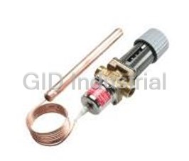
Danfoss 003N8182 Temp Regulator AVTA thermostatic valves
Part Number
003N8182
Price
Request Quote
Manufacturer
DANFOSS
Lead Time
Request Quote
Category
PRODUCTS - 0
Specifications
Capillary tube length Ft.
6'6"
Connection NPT
1"- 11 1/2
Cv-value US gpm
6.4
Max bulb temperature F
257
Setting range°F
32-86 , 77-149, 122-194
Type
AVTA 25
Features
- "Set and Forget!" The AVTA requires no power supply and is self-acting
- By placing the sensing bulb in the medium to be cooled, the AVTA will control the flow of cooling medium.
- Insensitive to dirt or fluid pressure
- Several bulb types and capillary tube lengths
- The AVTA thermostatically operated cooling valve is intended to proportionally control cooling processes.
Datasheet

Extracted Text
Data sheet Thermostatically operated cooling water valves Types AVTA and FJVA March 2000 DKACV.PD.500.D1.32 520B0131 Thermostatically operated cooling water valves Types AVTA and FJVA 2 Danfoss A/S 03-2000 DKACV.PD.500.D1.32 Thermostatically operated cooling water valves Types AVTA and FJVA Intoduction Thermostatically controlled valves are used The required temperature is maintained for the infinite proportional regulation of flow constant with no overconsumption of - cooling quantities, depending on the setting and the water in cooling systems - hot water or steam sensor temperature. in heating systems Thus operating economy and effenciency is maximized. The Danfoss range of thermostatic valves includes a series of industrial products for AVTB for heat regulation 1/2" → 1" both refrigeration and heating regulation. The AVTA for cooling regulation 1/2" → 1" valves are self-acting, i.e. they operate IVT for heat regulation 1/2" → 2" without a supply of auxiliary energy such as WVTS for cooling regulation 1 1/4" → 4" electricity or compressed air. For futher information please contact Because the valves constanly match flow Danfoss. quantity to demand they are especially suitable for temperature regulation. Technical data Thermostatic valves consist of three main elements. General Fig. 1 Setting section with knob, closing and setting scale. Fig. 2 Fig. 3 Valve body with orifice, closing cone Hermetically sealed thermostatic element and sealing elements. with sensor, bellows and charge Function When the three elements are built together 4. When balance is created between the two and the sensor is located at the point where opposing forces the valve spindle remains the temperature is to be regulated, the in its position. function sequence is as follows: 5. If the sensor temperature − or the setting − is changed, the point of balance becomes 1. A temperature-dependent pressure − displaced and the valve spindle moves charge vapour pressure − builds up in the until balance is re-established, or the valve sensor. is fully open or closed. 2. This pressure is transferred to the valve 6. On sensor temperature change the via the capillary tube and bellows and acts flow quantity change is approximately as an opening or closing force. proportional. 3. The knob on the setting section and the spring exert a force that acts counter to The illustrations show an AVTA cooling water the bellows. valve, but the function principle applies to all types of thermostatic valves. Danfoss A/S 03-2000 3 DKACV.PD.500.D1.32 Thermostatically operated cooling water valves Types AVTA and FJVA Application AVTA Self-acting AVTA cooling water valves are widely used for temperature regulation in many different machines and installations where cooling is required. AVTA always opens to admit flow on rising sensor temperature. The valve can be installed either in the cooling water flow line or return line. Typical application areas • Injection moulding machines • Compressors • Vacuum pumps • Dry cleaning machines • Distillashon plants • Printing machines • Hydraulic systems • Rollers/mills 1. Oil tank 2. Hydraulic machinery 3. Heat exchangers 4. Cooiing water supply 5. Cooling water valve type AVTA Fig. 4 • Opens on rising sensor temperature • Max. working pressure 232 Psi Specifications and • Media temperature −13° → +266 °F • The valves are pressure-relieved, i.e. products • Differential pressure 0 → 145 Psi the degree of opening is not affected by • Max. test pressure 362 Psi differenhal pressure Δp (pressure drop). No. Description Material 4 Spindle Brass(DIN 17660)W.No.20401 5 Diaphragms Ethylene-propylene-rubber(EPDM) 7 Valve body and other parts Forged brass(DIN 17660)W.No.2.0402 8 Valve cone Nitrile rubber (NBR) 9 Valve seat Stainless steel (DIN 17440)W.No.1.4305 12 Sensor Copper(DIN 1787)W.No.2.0090 13 Capillary tube gland Nitrile rubber(NBR),Brass DEN 17660 W.No. 2.0321 og W.No.2.0401 AVTA valves are available with three different types of charge. A. Adsorption charge Fig. 5 B. Mass charge AVTA C. Universal charge 4 Danfoss A/S 03-2000 DKACV.PD.500.D1.32 Thermostatically operated cooling water valves Types AVTA and FJVA AVTA with The charge consists of active carbon and CO Special characteristics 2 adsorption charge which are absorbed or absorbed on rising or • Can be installed in any position. falling sensor temperature and produce pres- • Withstands up to sure changes in the element. 266 °F sensor temperature • Small sensor dimensions - 0.4" × 6.3" • Max. pressure on sensor 362 Psi Regulating Capillary tube Connection Cv-value range length Type Code no. NPT °F US gpm Ft. 1/2"- 14 2.2 AVTA 15 003N6115 3/4"- 14 50 - 176 4.0 7' 6" AVTA 20 003N7120 1"- 11 1/2 6.4 AVTA 25 003N8125 Code no. covers complete value incl. capillary tube gland, sensor pockets, see "Accessories" Special characteristics AVTA with The charge is liquid / gas where the liquid sur- • Sensor dimensions 0.7" × 8.3" univeral chanrge face (regulation point) is always inside • Sensor can be installed colder or warmer the sensor. Which charge medium is used than the valve depends on the temperature range. • Sensors must be orientated as shown in the sketch. • Max. pressure on sensor 362 Psi "UP" = upwards Fig. 6 Capillary tube Max. bulb Setting Connection Cv-value Type length temperature range Code no. NPT Ft. US gpm °F °F 32- 86 l35 003N6132 AVTA 15 1/2" - 14 77-149 6' 6" 2.2 194 003N6162 122-194 257 003N6182 32- 86 135 003N7132 AVTA 20 3/4" - 14 77-149 6' 6" 4.0 194 003N7162 122-194 257 003N7182 32- 86 135 003N8132 AVTA 25 1"- 11 1/2 77-149 6' 6" 6.4 194 003N8162 122-194 257 003N8182 Code no. covers complete value incl. cappilary tube gland, sensor pockets, see „Accessories“, page 10. Danfoss A/S 03-2000 5 DKACV.PD.500.D1.32 Thermostatically operated cooling water valves Types AVTA and FJVA AVTA with mass charge The charge is liquid/gas.Because of the volumenetric conditions the liquid surface (regulation point) can be either in the sensor or the bellows, depending on the temperature conditions. Special caracteristics: • Small sensor dimensions −0.4" × 7.5" • Short time constant • Sensor must always be installed warmer than the valve • Max. pressure on sensor 362 Psi For further information please contact Fig. 7 Danfoss. Application FJVA F1VA valves are for applications where, because of installation problems, etc. it is desirable to avoid using capillary tube. This applies mainly where regulation accuracy requirements are more moderate and where an integral bypass can be accepted. In FJVA the whole bellows element is used as the sensor. The valve reacts against the cooling water temperature and therefore it must always be installed in the return line. Thus, indirect regulation is involved. Valves of this type operate with significantly longer time constants than AVTA valves where the sensor is located at the point at which the tempera- ture is to be regulated. FJVA is mainly used in systems where large and sudden load changes do not occur. Fig. 8 For further information please contact FJVA Danfoss. Sizing When sizing and selecting a thermostatic In general, the aim must be to select the valve, the most important point is to ensure smallest valve capable of ensuring that irrespective of the load the valve will adequate flow. always give the necessary quantity of cooling water. To be able to select a suitable size of A futher recommandation is that the valve, a necessary precondition is that temperature range be selected so that the information on the cooling effect is available. required sensor temperature lies at range On the other hand, the valve must not be too mid-point. large, otherwise there will be a risk of unstable regulation(hunting) . To enable fine adjustment of the valve, a thermometer should be installed near the The choise of charge is based on the tem- sensor. perature to be maintained, and on an assessment of the characteristics of the individual types, as previously described. 6 Danfoss A/S 03-2000 DKACV.PD.500.D1.32 Thermostatically operated cooling water valves Types AVTA and FJVA Valve size When selecting valve size, the following data applies: • Necessary cooling water quantity Q - US gpm • Temperature rise in cooling water Δt - F • Differential pressure across valve, Δp - Psi. When the valve is fully open the differential pressure ought to be about 50% of the total pressure drop across the cooling system. The diagrams make it easy to select valve Fig. 9 size. Example Fig. 10 Heating or cooling with water. Example A cooling water valve must be selected for the Given data Nessesary cooling effect 5 temperature regulation of a vacuum pump. • Necessary cooling effect TR with t = 20 °F. with full load 5 TR Flow is 6 US gpm. Since direct regulation of the oil temperature • Oil temperature to be maintained is required, select an AVTA. The sensor at 113 °F position is horisontal and small dimensions • Cooling water p = 60 Psi 1 are desirable. • Discharge p = 0 Psi 3 • Discharge temperature t = 88 °F 1 1. Using the graph in fig.10, you find the necessary cooling water quantity at Δt = 20 °F (88 − 68 °F) for 6 US gpm. Danfoss A/S 03-2000 7 DKACV.PD.500.D1.32 Thermostatically operated cooling water valves Types AVTA and FJVA Fig. 11 Relation between water quantity and pressure drop across valve. Example 2. Using the graph in fig. 11, you find the Operating conditions and other requirements Flow 6 US gpm with a necessary Cv-value for 6 US gpm at on the product in this example indicate that a pressure drop of 30 Psi. The Δp = 30 Psi ((60 − 0)/2) for 1.17 US gpm. valve with an adsorpsion charge is the most Cv-value becomes 1.17 US 3. It can be seen from the columns in fig.12 correct. The temperature range must be gpm. that all three AVTA valves ca n be used, but 50 → 176 °F. the preferable selection is a valve where The table on page 5 gives AVTA 15, code no. the necessary Cv-value lies in the middle 003N6115, which fulfill the requirements. of the range. So in practice an AVTA 15 To facilitate the installation a sensor pocket ought to be selected as it fully meets the is often used. A sensor pocket for ∅ 0,4" demand. sensor in brass, code. no. 993N3569, or in stainless steel, code no. 003N0196, is listed Consideration on the determination of valve under "Accessories" on page 10. size apply to both AVTA and FJVA. Fig. 12 Nomogram showing valve Cv-ranges. Cv- values are allways water flow in US gpm for a pressure drop Δp of 1 Psi. The preferable selection is a valve where the necessary Cv-value lies in the middle of the range, as a valve with a Cv-value close to either the max. or min. value is less stable and less precise due to either a relatively large Δp or ΔQ. Example: AVTA 15 is the most suitable for a Cv-value of 1.17 US gpm. 8 Danfoss A/S 03-2000 DKACV.PD.500.D1.32 Thermostatically operated cooling water valves Types AVTA and FJVA Fig. 13 Valve flow quantity in fully open position as a function of pressure drop Δp. Installation • The valves can be installed in any position. of AVTA / FJVA • An arrow on the valve body indicates the direction of the flow. • AVTA and FJVA are also marked so that the letters RA can be read straightforwardly when the valve is held as shown. • The installation of a filter ahead of the valve is recommended. Capillary tube Install the capillary tube without sharp bends (no „kinks“). Relieve the capillary tube at the ends. Relief is important where vibration might occur. Fig. 14 Note: Where AVTA is used, the sensor must be able to react to temperature variations in the cooling water on system start. Therefore a bypass line with shut-off valve might be necessary to ensure flow at the sensor during start-up. If a mounting bracket is used it must always be between valve body and setting section. Sensors must be installed as given in the description of the respective types. If sensor pockets are used, it is avantageous to apply heat-conductive compound to reduce the reaction time. See "Accessories" page 10. Fig. 15 Danfoss A/S 03-2000 9 DKACV.PD.500.D1.32 Thermostatically operated cooling water valves Types AVTA and FJVA Spare parts Service elements for AVTA Temperature Capillary Description Code no. range tube length °F Ft. Adsorption charge - sensor ∅ 0.4" × 6.39" 50 → 176 7' 6" 003N0278 Universal charge - sensor ∅ 0.7" × 8.3" 32 → 86 6' 6" 003N0075 16' 5" 003N0077 77 → 149 6' 6" 003N0078 16' 5" 003N0080 6' 6" amoured 003N0063 10" 003N0079 122 → 194 6' 6" 003N0062 Mass charge - sensor ∅ 0.4" × 7.5" 32 → 86 - 003N0066 See mounting instructions 77 → 149 6' 6" 003N0091 Service elements for AVTA Without capillary tube and sensor 32 → 86 - 003N0285 Fig. 16 Accessories Designation Description Code no. Sensor pocket, max. pressure 341 Psi, L = 8.7" Brass for ∅ 0.7" - sensor G 3/4" 003N0050 Brass for ∅ 0.7" - sensor 3/4"-14 NPT 003N0051 ss ∅ 0.7" 3/4" NPT 003N0053 18/8 steel ∅ 0.7" - sensor G 3/4" 003N0192 Sensor pocket, max. pressure 341Psi, L = 7.2" Brass for ∅ 0.4" - sensor G 1/2" 993N3569 18/8 steel for ∅ 0.4" - sensor G 1/2" 003N0196 Mounting bracket For AVTA / FJVA 003N0388 Heat-conductive compount 041E0110 1-off nitrile diaphragm for mineral oil For AVTA 15 003N0445 For AVTA 20 003N0446 For AVTA 25 003N0447 Capillary tube gland G 1/2" 017-4220 G 3/4" 003N0155 G 1/2"-14 NPT 003N0157 G 3/4"-14 NPT 003N0056 O-ring (2-off) For AVTA / FJVA 15 003N4006 Diaphragm (2-off) For AVTA / FJVA 20 003N4007 Valve cone (1-off) For AVTA / FJVA 25 003N4008 Top section For AVTA / FJVA 003N0001 10 Danfoss A/S 03-2000 DKACV.PD.500.D1.32 Thermostatically operated cooling water valves Types AVTA and FJVA lnstallation The valve can normally be fitted in the supply Elements with a small sensor ∅ 0.4" × 7.5" or return, in any position, provided the flow is ("sensor warmer") must always have the always in the direction indicated by the arrow. valve housing fitted in the inlet. Absorption charge Mass charge Universal charge Sensor ∅ 0.4" × 6.3" Sensor ∅ 0.4" × 7.5" Sensor ∅ 0.7" × 8.3" (sensor warmer or colder) (sensor warmer) (sensor warmer or colder) Dimensions a Weight Type H H LL 1 2 1 NPT lbs. AVTA 15 9.45 5.24 2.84 0.56 1/2" 3.20 AVTA 20 inch. 9.45 5.24 3.55 0.63 3/4" 3.31 AVTA 25 9.85 5.43 3.74 0.75 1" 3.64 Mounting bracket Capillary tube gland Sensor pocket ISO 9001 Danfoss A/S has achieved BSI Certification design, production and sales. BSI will meeting the international standard IS0 9001. currently supervise that Danfoss observes This means that Danfoss meets the inter- this standard as well as Danfoss own quality national standards of product development, control system. Danfoss A/S 03-2000 11 DKACV.PD.500.D1.32 Thermostatically operated cooling water valves Types AVTA and FJVA 12 Danfoss A/S 03-2000 AC-VM/con DKACV.PD.500.D1.32
Frequently asked questions
What makes Elite.Parts unique?

What kind of warranty will the 003N8182 have?
Which carriers does Elite.Parts work with?
Will Elite.Parts sell to me even though I live outside the USA?
I have a preferred payment method. Will Elite.Parts accept it?
Why buy from GID?

Quality
We are industry veterans who take pride in our work

Protection
Avoid the dangers of risky trading in the gray market

Access
Our network of suppliers is ready and at your disposal

Savings
Maintain legacy systems to prevent costly downtime

Speed
Time is of the essence, and we are respectful of yours
Related Products

DANFOSS 037H0031-23 CONTACTOR .75HP 115V 1PHASE
Request a Quote

The quote request has been received
Close

Facing challenges or have inquiries? Feel free to contact us!
Call Us +1-469-283-2440
What they say about us
FANTASTIC RESOURCE
One of our top priorities is maintaining our business with precision, and we are constantly looking for affiliates that can help us achieve our goal. With the aid of GID Industrial, our obsolete product management has never been more efficient. They have been a great resource to our company, and have quickly become a go-to supplier on our list!
Bucher Emhart Glass
EXCELLENT SERVICE
With our strict fundamentals and high expectations, we were surprised when we came across GID Industrial and their competitive pricing. When we approached them with our issue, they were incredibly confident in being able to provide us with a seamless solution at the best price for us. GID Industrial quickly understood our needs and provided us with excellent service, as well as fully tested product to ensure what we received would be the right fit for our company.
Fuji
HARD TO FIND A BETTER PROVIDER
Our company provides services to aid in the manufacture of technological products, such as semiconductors and flat panel displays, and often searching for distributors of obsolete product we require can waste time and money. Finding GID Industrial proved to be a great asset to our company, with cost effective solutions and superior knowledge on all of their materials, it’d be hard to find a better provider of obsolete or hard to find products.
Applied Materials
CONSISTENTLY DELIVERS QUALITY SOLUTIONS
Over the years, the equipment used in our company becomes discontinued, but they’re still of great use to us and our customers. Once these products are no longer available through the manufacturer, finding a reliable, quick supplier is a necessity, and luckily for us, GID Industrial has provided the most trustworthy, quality solutions to our obsolete component needs.
Nidec Vamco
TERRIFIC RESOURCE
This company has been a terrific help to us (I work for Trican Well Service) in sourcing the Micron Ram Memory we needed for our Siemens computers. Great service! And great pricing! I know when the product is shipping and when it will arrive, all the way through the ordering process.
Trican Well Service
GO TO SOURCE
When I can't find an obsolete part, I first call GID and they'll come up with my parts every time. Great customer service and follow up as well. Scott emails me from time to time to touch base and see if we're having trouble finding something.....which is often with our 25 yr old equipment.
ConAgra Foods