

 Manufacturers
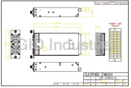
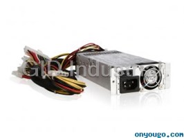
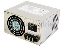
CLAYPOWER CP-10030
Description
ClayPower CP-10030 300W, Output: +3.3V/22.0A, +5.0V/30.0A, +12.0V/11.0A, -5.0V/1.0A, -12.0V/1.0A, +5.0VSB/1.5A; Redundant Power Supply
Part Number
CP-10030
Price
Request Quote
Manufacturer
CLAYPOWER
Lead Time
Request Quote
Category
PRODUCTS - C
Datasheet

Extracted Text
SWITCHING POWER SUPPLY SPECIFICATION CP-10030-V TEL 626.303.8885 FAX 626.301.0588 727 Phillips Dr. City of Industry, CA 91748 www.claypower company.com 1. Input Characteristics: 1.1 Input Voltage Range --------------------- 90~264Vac,Full Range With Active Power Factor Correct 90% Min 1.2 Input Frequency Range ----------------47Hz To 63Hz. 1.3 Input Ac Current ( Max ) ----------------6.3A Max. @115Vac, 3.0A Max. @230Vac Full Load. 1.4 Inrush Current -----------------------------At 132Vac / 264Vac, Full Load Condition, No Damage Occur. Input Fuse Shall Not Blow. 1.5 Efficiency ----------------------------------- 63% Min, At Nominal Line Input Full Load. 1.6 Input Leakage Current -------------- Leakage Current From Line to Ground Will Be Less 3.5mA rms. Measurement Will Be Made At 240Vac/60Hz. 2. Output Characteristics: 2.1 Static Output Characteristics. Output Load Range Regulation Ripple Max Ripple & Noise Voltage Min. Max. Min. Max. mV P-P Max. mV P-P 1. +3.3 V 0.3 A 22.0 A - 5 % + 5 % 50 mV 100 mV 2. +5.0 V 2.5 A 30.0 A - 5 % + 5 % 50 mV 100 mV 3. +12.0 V 0.5 A 11.0 A - 5 % + 5 % 100 mV 150 mV 4. -5.0 V 0.0 A 1.0 A - 10 % + 10 % 150 mV 200 mV 5. -12.0 V 0.0 A 1.0 A - 10 % + 10 % 150 mV 200 mV 6. SB +5.0 V 0.0 A 1.5 A - 5 % + 5 % 100 mV 100 mV Note: 1. Noise Test ----- Noise Bandwidth Is From Dc To 20MHz. 2. Ripple Frequencies Greater Than 1 MHz Shall Be Attenuated By the Measurement System. 3. Add 0.1uF / 10uF Capacitor At Output Connector Terminals For Ripple & Noise Measurements. 4. Combined Total Power From +3.3V And +5V Rails Shall Not Execeed 160W. 5. The Total Output Power Shall Not Exceed 300W. 2.2 Dynamic Output Characteristics: 2.2.1 Initial Delay Time ----- NONE. 2.2.2 Rise Time ------------------ 50 mS Max. At Nominal Line Full Load. 2.2.3 Turn-on Delay Time ----- 600mS Max. At Nominal Line Full Load. 2.2.4 Hold-up Time ------------- 16mS min. For + 5V Output At Nominal Line Full Load. 2.2.5 Transient Overshoot --- 10% Max. Of Delay State After Load Change Of 25% Within The Range Of 50% To 100% Of Full Load. 2.2.6 Temperature Coefficient ----- 0.03% Per �C Max. 3. Protections: 3.1 Over Voltage Protection --- Standard On +3.3V Output Set At 3.7Vdc – 4.5Vdc. +5.0V Output Set At 5.7Vdc – 6.5Vdc. +12.0V Output Set At 13.5Vdc – 14.5Vdc. 3.2 Short Circuit Protection --- A Short Circuit Placed Between DC Return And Output Shall Cause No Damage And The Power Supply Shall Shutdown. 3.3 Over Power Protection --- The Power Supply Can Use Electronic Circuit To Limit The Output. Power Against Excessing +120% - 170% Of Full Load. Or Protected against Excessive Power Delivery Due To Short Circuit Of Any Output Or Over Total Power. 3.4 No load Operation -------- No Parts Damaged On Power Supply. 4. Dielectric Withstand Voltage: 4.1 Primary to Secondary -------- 1500Vac For 1 Minute. Or 2200Vdc For 3 Sec. 4.2 Primary to Safety Ground --- 1500Vac For 1 Minute. Or 2200Vdc For 3 Sec. 4.3 Insulation Resistance --------- Primary To Safety Ground - 500Vdc, 100M ohms Min. 5. Conducted EMI: Internal Filter Can Meet. 5.1 FCC Requirement --- Part15, SUB-Part J, Computing Devices “ Class A “ Limits. 5.2 VDE Requirement --- Class “ A “ ( General Operating Permit ) Requirements Of VFG 234/1991. 5.3 CISPR Requirement --- Class “ A “ Requirements Of CLSPR 22. 5.4 Harmonic Requirement ---IEC10000-3-2 & IEC10000-3-3 Class “ D “. 6. Product Safety: This Power Supply Is Designed Can Meet The Following Spec. 6.1 UL/CUL -------------------- UL1950 6.2 TUV ------------------------- EN 60950 7. Environment: 7.1 Operation Temperature --------------- Air Temperature 0 �C To 50 �C. 7.2 Operation Relative Humidity -------- 20% To 90%. 7.3 Storage Temperature ------------------ Air Temperature -20 �C To 60 �C. 7.4 Storage Relative Humidity ----------- 5% To 95%. 7.5 Altitude ------------------------------------- Operate Properly At Any Altitude Between 0 To 100,000 Feet. Storage 40,000 Feet. 7.6 Vibration ----------------------------------- 0.38mm. 5-55-5Hz, 1 Minutes Per Cycle; 30 Minutes For Each Axis ( X,Y,Z ). 8. Burn-In 8.1 Burn-In ------------------------------------- At 45 �C, Max. Load, 4 Hours. 9. Mean Time Between Failure ----- 100 KHrs Minimum At 75% Load For 25 �C Ambient Temperature. 10. Power-Good Signal: +4.75V +4.75V Ts -> +5V Output Power Good Signal <- Tr -> Td -> -> T1 <- !!!!!!!!!!!!!!!!!!Opuf;!Us! !211!nt-!U2! !2!nt-!Ue!>!211!!611!nt/! � � – 11. Dimension 11.1 W x H x D --------------------------------------- 100.0 x 46 x 205.2( mm ) DMBZQPXFS!DPNQBOZ DQ.21141.W 1PSA300RM1-A1 1PSA300RM1 A1 05/25'06 1:2 1of1 ! ! ! !
Frequently asked questions
What makes Elite.Parts unique?

What kind of warranty will the CP-10030 have?
Which carriers does Elite.Parts work with?
Will Elite.Parts sell to me even though I live outside the USA?
I have a preferred payment method. Will Elite.Parts accept it?


What they say about us
FANTASTIC RESOURCE
One of our top priorities is maintaining our business with precision, and we are constantly looking for affiliates that can help us achieve our goal. With the aid of GID Industrial, our obsolete product management has never been more efficient. They have been a great resource to our company, and have quickly become a go-to supplier on our list!
Bucher Emhart Glass
EXCELLENT SERVICE
With our strict fundamentals and high expectations, we were surprised when we came across GID Industrial and their competitive pricing. When we approached them with our issue, they were incredibly confident in being able to provide us with a seamless solution at the best price for us. GID Industrial quickly understood our needs and provided us with excellent service, as well as fully tested product to ensure what we received would be the right fit for our company.
Fuji
HARD TO FIND A BETTER PROVIDER
Our company provides services to aid in the manufacture of technological products, such as semiconductors and flat panel displays, and often searching for distributors of obsolete product we require can waste time and money. Finding GID Industrial proved to be a great asset to our company, with cost effective solutions and superior knowledge on all of their materials, it’d be hard to find a better provider of obsolete or hard to find products.
Applied Materials
CONSISTENTLY DELIVERS QUALITY SOLUTIONS
Over the years, the equipment used in our company becomes discontinued, but they’re still of great use to us and our customers. Once these products are no longer available through the manufacturer, finding a reliable, quick supplier is a necessity, and luckily for us, GID Industrial has provided the most trustworthy, quality solutions to our obsolete component needs.
Nidec Vamco
TERRIFIC RESOURCE
This company has been a terrific help to us (I work for Trican Well Service) in sourcing the Micron Ram Memory we needed for our Siemens computers. Great service! And great pricing! I know when the product is shipping and when it will arrive, all the way through the ordering process.
Trican Well Service
GO TO SOURCE
When I can't find an obsolete part, I first call GID and they'll come up with my parts every time. Great customer service and follow up as well. Scott emails me from time to time to touch base and see if we're having trouble finding something.....which is often with our 25 yr old equipment.
ConAgra Foods