

 Manufacturers
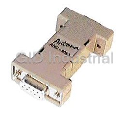
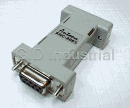
ANTONA ANC-6090
Description
Antona ANC-6090 Provides the user with a low cost solution to change RS-232C level transmit and receive level signals into RS-485, or RS-422 differential level noise immune signals.
Part Number
ANC-6090
Price
Request Quote
Manufacturer
ANTONA
Lead Time
Request Quote
Category
RS232 TO RS485
Specifications
Adapter case size
2.2" X 1.2"
Connectors
Female DB9 to Pc
Female
DB9 to RS-422/485 equipment
Power requirements
6 ma for short cable, non-terminated applications 100 ma for long and/or terminated cable applications
RS-422/485 output drive
short proof output, non-terminated operation to 150 feet, terminated operation with external power supply to 4000 feet.
RS232 output drive
short proof output, under worse case conditions, ± 5v switching to exceed ± 3v EIA RS232 specification
Features
- 4-wire full duplex or 2-wire half duplex operation (RTS for transmit control)
- Baud rates to 921.6 Kbaud (tested to 1.1Mbps)
- Powered from serial port for most installations
- Server/Client jumper selectable
- Transmit/Receive data up to 4,000 feet (1,219 m).
Datasheet

Extracted Text
Rev. B $ 5.00 ANC - 6090 RS-422/485 Serial Communications Adapter Antona Corporation, Los Angeles, CA Antona Corporation, Los Angeles, CA Antona Corporation (818)783-4299 i Antona Corporation Copyright Copyright (c) 2003 by Antona Corporation. All rights reserved. No part of this publication may be reproduced, transmitted, transcribed, stored in a retrieval system, or translated into any language or computer language, in any form or by any means, electronic, mechanical, magnetic, optical, chemical, manual or otherwise, without the prior written permission of the Antona Corporation of Los Angeles, California. Warranty Antona Corporation products are warranted to be free from defects in materials and workmanship for a period of one (1) year from the date of original shipment to customer. This warranty is limited to the replacement or repair of parts not subjected to misuse, neglect, unauthorized repair, alteration (except card options), accident, or failure due to the effects of static electricity discharge. In no event shall Antona Corporation be liable to the purchaser for loss of use, profit, or consequential damages, or damages of any kind, including, but not limited to, accidental loss or damage to other equipment, arising out of use of Antona Corporation equipment, whether or not said equipment was used properly. The designer is responsible for the determining the suitability and use of the product. This warranty is in lieu of any other warranty, expressed, implied, or statutory, including, without limitation, any implied warranty or merchantability or fitness for a particular purpose. No amendment of this warranty may be effected except in writing by an officer of the Antona Corporation. All repair services shall be performed at the Antona Corporation plant in Los Angeles, Ca. THE PURCHASER MUST OBTAIN A RETURN AUTHORIZATION FROM THE ANTONA CORPORATION PRIOR TO RETURNING ANY PIECE OF EQUIPMENT. Shipment to the Antona Corporation will be at the expense of the purchaser, return shipment will be at the expense of the Antona Corporation for all warranty repairs. Antona Corporation (818)783-4299 1 TABLE OF CONTENTS Features_________________________________________________________________________ 3 Overview ________________________________________________________________________ 3 Mechanical Specifications ________________________________________________________________ 3 Electrical Specifications__________________________________________________________________ 3 Adapter Installation_____________________________________________________________________ 4 Serial Port Powering ____________________________________________________________________ 4 External Powering______________________________________________________________________ 4 Adapter Jumper Options____________________________________________________________ 5 Figure 1 - jumper locations_____________________________________________________________________5 Transmit Control Enable - JP1 ___________________________________________________________ 5 Auto Transmit Source - JP2 ______________________________________________________________ 6 Photo 1 – RTS Transmit Operation ______________________________________________________________6 Receive Enable - JP3____________________________________________________________________ 6 Cable Termination - JP4_________________________________________________________________ 6 Transmit/Receive Pin Reverse Jumpers – JP5/JP6____________________________________________ 7 figure 2 – Tx/Rc Pin Reverse Jumpers____________________________________________________________7 DCD Drive – JP7_______________________________________________________________________ 7 ANC-6090 External connections _____________________________________________________ 8 DB9 to DB25 pin to pin chart - for use of adapter on a DB25 type com port_______________________ 8 RS-422/485 connections to the ANC-6090 _____________________________________________ 8 DB9 RS-422/485 Signals for Master (Multimedia Controller)___________________________________ 9 DB9 RS-422/485 Signals for Server (Receive from Master) ____________________________________ 9 RS-485 Two and Four Wire Interfacing _______________________________________________ 9 2-wire ________________________________________________________________________________ 9 figure 3 – typical 2-wire RS-485 interface________________________________________________________10 Photo 2 – 2-wire interface example _____________________________________________________________10 4-Wire_______________________________________________________________________________ 10 Appendix A – Troubleshooting Guide ________________________________________________ 11 Loopback Test________________________________________________________________________________11 CABLING (most common problem) _______________________________________________________________11 Pin Signal Definition (4-wire interfaces)___________________________________________________________11 Multidrop Cabling (2-wire interfaces) _____________________________________________________________11 Data Direction Jumpers ________________________________________________________________________12 Signal Control Jumpers_________________________________________________________________________12 Cable Termination ____________________________________________________________________________12 Powering ____________________________________________________________________________________12 Program Operation ____________________________________________________________________________13 RS422/485 Equipment _________________________________________________________________________13 Plugged in Backwards__________________________________________________________________________13 Now What? __________________________________________________________________________________13 Appendix B -Circuit Board Schematic________________________________________________ 14 Antona Corporation (818)783-4299 2 Features Transmit data at distances up to 4000 feet (1219.2 m) Transmit data at distances up to 4000 feet (1219.2 m) Baud rates to 1 Mbaud Baud rates to 1 Mbaud Powered from serial port for most installations Powered from serial port for most installations 4 4 w wiir re e ffu ullll d du up plle ex x o or r 2 2 w wiir re e h ha allff d du up plle ex x o op pe er ra attiio on n ( (R RT TS S llo ow w) ) O Op pe er ra atte e iin n m mu ullttiid dr ro op p // m mu ullttiip po oiin ntt a ap pp plliic ca attiio on ns s ( (R RS S- -4 48 85 5) ) J Ju um mp pe er ra ab blle e tte er rm miin na atte e ( (1 12 20 0 o oh hm ms s) ) o on n iin np pu utt Selectable data loopback feature or data echo suppression (in 2-wire applications) Selectable data loopback feature or data echo suppression (in 2-wire applications) Choice of fixed or RTS high controlled transmit Choice of fixed or RTS high controlled transmit Latest surface mount technology (SMT) for low power and small size Latest surface mount technology (SMT) for low power and small size P Pllu ug g c co om mp pa attiib blle e w wiitth h D DB B- -9 9 P Pc c R RS S- -2 23 32 2C C s se er riia all p po or rtts s P Piin n c co on nn ne ec cttiio on ns s o on n c co on nv ve er rtte ed d R RS S- -4 42 22 2 s siig gn na all s siid de e m ma atte e d diir re ec cttlly y tto o m ma an ny y p pr ro offe es ss siio on na all m mu ullttiim me ed diia a u un niitts s ( (S SM MP PT TE E iin ntte er rffa ac ce e ffo or r S So on ny y,, B BT TS S,, G Gr ra as ss s V Va alllle ey y,, A Am mp pe ex x,, e ettc c..) ) Overview The ANC-6090 adapter converts the serial port RS-232C level transmit and receive signals on an IBM compatible personal computer (Pc), or any device with an RS-232C type interface, into bipolar-current RS-422 or RS-485 compatible signals. The adapter interface voltage levels produced meet the EIA-232, TIA-232, RS-422 and RS-485 signals. These adapters find wide use in high-speed long distance serial communications or to interface a Pc with equipment that uses an RS-422 or RS-485 type input/output. The adapter is powered by the host system’s serial port signal lines, the same way a serial port “mouse” interface is powered. For most installations this eliminates the need for an external power supply making this adapter an ideal choice for portable use. Extended cable runs and/or terminated RS-422/485 connections may require more current than the serial port power can provide so the RS-422/485 connector can accept +3v to +12v regulated DC at 100 milliamps to provide the added power to drive the adapter. Mechanical Specifications Adapter case size: 2.2" X 1.2" Connectors: Female DB9 to Pc Female DB9 to RS-422/485 equipment Electrical Specifications Power requirements= 6 ma for short cable, non-terminated applications 100 ma for long and/or terminated cable applications RS-422/485 output drive= short proof output, non-terminated operation to 150 feet, terminated operation with external power supply to 4000 feet. RS232 output drive=short proof output, under worse case conditions, ±5v switching to exceed ±3v EIA RS232 specification Antona Corporation (818)783-4299 3 Adapter Installation Turn off the personal computer and any other remote equipment before performing the adapter installation. Never install or remove the adapter with the power applied to the Pc or any of the attached equipment. This could result in permanent damage to the adapter due to static discharge. Normally the adapter is plugged directly into the serial port male DB-9 jack on the back of the Pc. Be sure to look at the label on the adapter to identify and insure that the proper DB9 is plugged into the Pc’s serial jack. The ANC-6090 has female DB9s at both ends. The user should screw the 2 mounting screws into the serial port’s hex nuts for permanent installations to assure good long-term connection. The adapter may be attached to a ribbon cable type extension from the Pc to the Antona adapter. This is sometimes useful when the space is limited behind the Pc. The ribbon cable extension should not exceed 3 feet. A 12’ shielded wire cable could also be used. Remember that the signal is still RS-232C level leaving the computer and entering the adapter. Also note that if the designer is using a DB9 to DB25 adapter an A-B selector box or break-out box for testing, that all 9 pins should be connected through the adapter or test setup. The main ANC-6090 adapter power is drawn from the host system’s RTS and DTR lines, like a mouse interface. Serial Port Powering Three of the Pc’s serial port RS-232C level signals can be used by the Antona adapter to derive power from: RTS, DTR and TX. The user must therefore insure that the RTS and DTR signals from the Pc’s serial port are brought to a high output level 100 ms before communicating over the adapter. Usually this is performed once during the user’s program initialization. When the appropriate jumper is set, RTS is lowered and raised to transmit and receive respectively for use in 2-wire interfaces. External Powering An external DC power source may be feed into pin 9 on the RS-422/485 DB-9 connector to supply the additional current that the adapter may need. The table “RS- 422/485 Connections to the ANC-6090” (page 9) shows the pins for using an external source of DC to power the adapter. There are also two pads on the circuit board you can solder leads to for applying external power. A small hole in the plastic case would need to be added to run the power supply leads away from the adapter. Figure 1 below shows the pad as black dots. The +3v to +12v regulated DC is soldered to the pin located just to the right of JP7, and the power supply ground pin is soldered to the pad just above JP4. Antona Corporation (818)783-4299 4 Adapter Jumper Options Figure 1 - jumper locations When shipped, the ANC-6090 is set for transmit and receive enabled always. The output pins are set for ‘master’, the terminating resister is disconnected and RTS is connected to DCD (JP7). All references to ‘horizontal’ and ‘vertical’ below are in respect to figure 1 above. The schematic gives another view of each jumper showing the settings on isolated block drawings of each jumper function. To open the enclosure hood use a small flat blade screwdriver and carefully pry the plastic latches on one side of the enclosure and gently separate the sides slightly (about .020”). Place a paper clip or coin between the separated sides of the enclosure to keep it from relatching shut while you repeat the process on the two plastic latches on the other side of the hood. The two sides of the hood should now come apart. The computer side mounting screws are loose within the enclosure so be careful of these small parts. To reassemble the enclosure hood back around the adapter electronics, place the circuit board into the enclosure half that designates signal direction with the RS-422/485 connector (the DB-9 connector that has the jackscrews) on the arrowed end pointed to by the small “RS422” designation. Now place the small screws back into position on the RS232, or computer side, DB-9. Double check that the hood labeled with which end is RS-232 and RS-422 is properly oriented before pushing the sides together and relatching the plastic shells. Remember - the RS-422 end of the adapter is the end with the jack nuts mounted onto the female DB-9 connector. Transmit Control Enable - JP1 For single adapter 4-wire setups where the ANC-6090 is controlling one piece of equipment, JP1 can be set in the horizontal position, as shipped, so that the transmit data RS-422/485 driver lines are always asserted. For battery powered applications, it may be desirable to turn off the transmit drivers to save current when there is no data being transmitted using the RTS control line. When using the RTS signal to control the driver output, the vertical position should be set. See Appendix B, the middle left hand of the schematic for the location of JP1. The photo 1 below shows how lowering the RTS line on the RS-232 side of the adapter (lower trace – showing RTS signal after being translated to the inverted TTL level within the adapter) precedes transmitting the data byte out the TX+ line (upper trace). Antona Corporation (818)783-4299 5 Auto Transmit Source - JP2 This jumper is for the ‘autoxmit’ feature of our ANC-6085 version adapter and is just left in the horizontal position (as shipped) on the ANC-6090. See Appendix B, the lower left hand of the schematic for the location of JP2. Photo 1 – RTS Transmit Operation RTS may also be used to turn on/off the receive input lines (see JP3 below). When RTS is used, asserting the RS-232 signal ‘low’ to the adapter enables transmitting while RTS ‘high’ enables receiving. Note that DTR must be set high when RTS is low in order for the adapter to operate when an external power supply is not being used. Receive Enable - JP3 This 3-pin straight vertical jumper can be set to enable receiving RS-422/485 data always (as shipped, JP3 set on the lower and middle pin), or turned off automatically whenever the transmit driver is set active by RTS (JP3 set on the middle and upper pin). See Appendix B, the middle left hand of the schematic for the location of JP3. On a 2-wire interface if data is being transmitted and the receiver is also enabled, anything transmitted will be ‘looped-back’ into the serial port. Since the echoed signal is the actual data that was transferred to the interface cable, being able to see the transmitted data echoed back may be of use for testing, authenticating, diagnostics of data output or determining when RTS can be lowered if used to control transmission. Cable Termination - JP4 For installation cable lengths greater than 150 feet, resister termination across the remote receive pair end of the cable may be necessary. The ANC-6090 has a ½W 120 ohm termination resister built in that can be placed across the receive wire pair by setting jumper 4 (JP4) located over the transmit/receive setting jumpers. As described above, an external DC power source may be feed into pin 9 on the RS-422/485 connector to supply the additional current that the adapter may need when terminating resisters are installed on the receive/transmit wire pairs. Note that some multimedia equipment have internally connected circuitry for 120 ohm resister termination. If So, then even if the separation distance is less than 150 feet, it may be necessary to provide an external source of DC. Some equipment Antona Corporation (818)783-4299 6 also allows the user to disconnect the internal termination network for short cable runs. See Appendix B, the upper middle of the schematic for the location of JP4. Transmit/Receive Pin Reverse Jumpers – JP5/JP6 These two jumper sets, designated JP5 and JP6 on the circuit board and schematic, allow the designer to swap the transmit and receive pairs on the RS-422/485 side of the adapter. The configuration as shipped from Antona is set for ‘master’. This configuration is for the adapter acting as a controller to multimedia type equipment with an RS-422 SMPTE interface. Figure 1 shows the jumper locations from the component side of the circuit board. The user may move all four jumper shunts on the component side of the card from the ‘horizontal’ controller configuration to the ‘vertical’ receiver configuration. All four shunts must be changed to either all horizontal or all vertical for proper adapter operation figure 2 – Tx/Rc Pin Reverse Jumpers DCD Drive – JP7 This 2-pin jumper disconnects the DCD serial port input line from the RTS signal output. When not jumpered a small amount of current is saved by not holding the DCD line high when RTS is high. RTS is one of the two main power sources for the adapter and is used to control the transmit and receive function in RS-485 type configurations. This jumper is enabled when shipped by a short trace between the two jumper pads on the solder side of the PCB. If the designer wishes to disconnect the RTS to DCD connection, just use an Exacto knife to cut and remove the small trace between the two pads of JP7. Reconnection may be performed by soldering in a small wire through the two pad holes of JP7. See Appendix B, the upper middle of the schematic for the location of JP7. Be sure to verify that the application program either does not rely or use the state of the DCD input pin for operation. Antona Corporation (818)783-4299 7 ANC-6090 External connections Signal Function DB-9 Pin # Comment Data Direction DCD/R Data Carrier Detect 1 Connected via JP7 input to computer LSD to RTS RX RECEIVE DATA 2 RS-232 level input input to computer TX TRANSMIT DATA 3 RS-232 level output output from computer DTR Data Term Ready 4 +v to power output from computer adapter GND GROUND 5 Signal ground I/O signal ground DSR Data Set Ready 6 Tied to DTR (pin 4) input to computer RTS Ready to Send 7 +v to power output from computer adapter CTS Clear to Send 8 Tied to RTS (pin 7) input to computer RI Ring Indicator 9 Not connected input to computer DB9 to DB25 pin to pin chart - for use of adapter on a DB25 type com port Function DB-9 Pin # DB-25 Pin Comment DCD/RLSD Data Carrier Detect 1 8 RX RECEIVE DATA 2 3 RS-232 level input TX TRANSMIT DATA 3 2 RS-232 level output DTR Data Term Ready 4 20 +v to power adapter GND GROUND 5 7 signal ground DSR Data Set Ready 6 6 tied to DTR (pin 4) RTS Ready to Send 7 4 +v to power adapter CTS Clear to Send 8 5 RI Ring Indicator 9 22 RS-422/485 connections to the ANC-6090 For multimedia control interfacing, the jumpering of JP5/6 is set for ‘master’ (as shipped). A 9-pin male to 9-pin male cable wired pin-to-pin is used to connect to the multimedia device. For other interfaces, the user hand-wires a 9-pin cable assembly from the RS-422/485 piece of equipment to the Antona adapter with the appropriate pin to signal interface. The only difference between the ‘master’ and ‘server’ (slave) version is the jumper positions of JP5 and JP6 within the adapter. The electronics are exactly the same, only the 2 transmit and 2 receive signal lines are exchanged on the RS-422/485 side of the adapter. Antona Corporation (818)783-4299 8 DB9 RS-422/485 Signals for Master (Multimedia Controller) DB9 CONN (J2) FUNCTION IDENTIFICATION 1 GROUND ground for RS-422/485 and/or external power (same function as pin 5) 2 RC- RS-422/485 minus side input 3 TX+ RS-422/485 plus side output 4 -not used- 5 GROUND ground for RS-422/485 and/or external power (same function as pin 1) 6 -not used- 7 RC+ RS-422/485 plus side input 8 TX- RS-422/485 minus side output 9 +V Optional +3V to +12V DC @ 100ma DB9 RS-422/485 Signals for Server (Receive from Master) DB9 CONN (J2) FUNCTION IDENTIFICATION 1 GROUND ground for RS-422/485 and/or external power (same function as pin 5) 2 TX- RS-422/485 minus side output 3 RC+ RS-422/485 plus side input 4 -not used- 5 GROUND ground for RS-422/485 and/or external power (same function as pin 1) 6 -not used- 7 TX+ RS-422/485 plus side output 8 RC- RS-422/485 minus side input 9 +V Optional +3V to +12V DC @ 100ma RS-485 Two and Four Wire Interfacing 2-wire Usually a two wire interface with multiple peripherals uses a ‘polled-response’ half-duplex software protocol where each device has a unique device code. Generally, this requires externally powering the Antona adapter, but for short cable runs to non-terminated equipment operating at medium baud rates (like 9600 or less) an external power supply may not be needed. The designer should use twisted pair wire with a impedance of 100 to 120 ohms. Low-cost CAT-5 UTP (Unshielded Twisted Pair) wire works fine. The user must externally wire the cable with pin 3 connected to pin 7 (TX+ to RC+) and pin 8 to pin 2 (TX- to RC-) on the RS-485 connector side of the adapter. The 2 conductor cable which connects to the outside world is then wired to pin 7 (+DATA) and to pin 2 (-DATA) of the RS-485 compatible peripheral (see figure 3 below). We offer an ANC- CKIT cable kit, with all the hardware needed and 25 feet of CAT-5 UTP wire for this application. Antona Corporation (818)783-4299 9 figure 3 – typical 2-wire RS-485 interface The photo below (photo 2) shows a typical transmission and reception over an RS-485 2-wire interface. The top trace shows the data transmitted from the ANC-6090 with a scope probe on the nd TX+/RC+ combined line. The 2 group of noisy looking characters is the response received from a remote device about 4 ms after the last character is sent through the ANC-6090. The lower trace (#2) shows the RS-232 level signal on pin 2 of the RS-232 DB-9 going back to the Pc after being cleaned up by the adapter and converted back into a bipolar signal. The 9600 baud data depicted being transmitted and received is through a MODCOM protocol based polled-response type industrial controller. Photo 2 – 2-wire interface example 4-Wire A 4-wire RS-485 interface uses 2-wires to transmit to all connected peripheral receive data lines, and 2-wires connected from all peripheral transmit pairs back to the server’s receive wire pair. In such an arrangement, the server can be transmitting and receiving at the same time (full duplex) and no ‘polled-response’ protocol or unique device code is necessary resulting in an overall improvement in communication speed. Antona Corporation (818)783-4299 10 Appendix A – Troubleshooting Guide RS232/RS422/RS485 Serial Interfaces Here are the most common sources of interfacing problems and tests you can make to diagnose your interface: Loopback Test You can verify that the Antona adapter is working by doing a simple loopback test using a male DB9 connector with a wire connection from pin 3 to 7 and pin 8 to 2. You can also add external power by soldering a 9v battery clip between pin 1 (ground) and pin9 (+V). Use a simple terminal program to just test that characters sent out the serial port are echoed back through the adapter. Make sure that your terminal program is turning on RTS and/or DTR to power the Antona adapter, and that the program is set to control the com port that the adapter is connected to. Put the signal control jumpers (JP1/2/3) back to default condition if they have been moved. The adapter operation does not rely on baud rate, parity, stop bits - but the actual application program you are using with the adapter may (see PROGRAM OPERATION below). CABLING (most common problem) If one of the interface wires used is not connected (open) or shorted, the whole interface will appear not to be working. Try using another cable or try the loopback test described above at the end of the cable to verify operation. If you can not get the loopback test to work through the cable, it will not work in your application. Even cables purchased with molded ends can be damaged. We test all of the cables we sell before shipping them out. Pin Signal Definition (4-wire interfaces) Take a look at the manual of the RS422/485 equipment that you are trying to control. Be sure that the pin definition on the equipment tells you the signal names, not what they are suppose to connect to. This sounds simple, but unless you know which direction the pinouts are defined from, you will connect TX+ to TX+ which is incorrect. Make sure that you have the TX+ on the Antona adapter connected to the RC+ on the RS422/485 equipment and TX- connected to RC- (same for the signal coming back from the RS422/485 side - make sure that the Antona adapter's RC+ is connected to the TX+ and that the RC- is connected to the TX- on the RS422/485 side. Pin 5 on the Antona adapter's RS422 output side should be connected to the ground of the RS422/485 equipment. Multidrop Cabling (2-wire interfaces) Check to make sure you have connected the ‘plus’ signal lines to the like ‘plus’ signal lines and ditto for the ‘negative’ to the ‘negative’ signals. Try connecting just one piece of equipment to the adapter for debugging both the cabling and the software interfacing. Remember that multidropped peripherals must each be assigned a unique ‘device code’. Check with the specific equipment’s User’s Manual for setting this, along with protocol, baudrate, character length, parity and stop bits. Antona Corporation (818)783-4299 11 Data Direction Jumpers When shipped the Antona adapter is set for a SMPTE MASTER interface. Connector pinouts are in this manual for both MASTER and SERVER (SLAVE) mode, so be sure you are looking at the correct table. You may also want to open the Antona adapter up and verify the jumpers JP5/6 are set for the mode you desire. All 4 jumpers should be installed, they each represent one of the 4 signals being transmitted and received. The Appendix B Schematic shows how and where these jumpers are located. Signal Control Jumpers There are three main jumpers – JP1/2/3 that control the operation of the signal switching on the ANC-6090 for transmit and receive enabling. Double check that you have set the jumpers correctly for your application. All three jumpers must be installed for the adapter to work properly and it is possible to have one mis-setting cause the adapter to appear non- operational. Check the adapter jumper settings against the Appendix B schematic (left hand side). As a baseline, restore all jumper settings to the factory defaults shown on the schematic. Cable Termination Reflected signal produced by cabling that is not terminated properly will cause data transmission errors. A terminated cable matched to the impedance of the cable wire produces the maximum signal transfer and dampens the ringing of a reflected signal. If you are using the adapter to interface with one piece of equipment with a short cable run (under 150 feet) in an electrically ‘clean’ environment (like an office) then you probably do not need the cable to be terminated. If on the other hand you are using the ANC-6090 to interface with 2 or more RS-485 devices in an industrial environment with hundreds of feet of cable runs – terminating both ends of the cable at the end points would be required. The adapter has a jumper enabled 120 ohm resister (JP4) that takes care of the adapter end of the cable. The user must connect a similar resister at the far end of the cable run. An unterminated cable will not work generally with long cable runs, and baudrates above 2400 baud. Externally powering the adapter for such an application would certainly be required. The best way to determine if termination is causing your interface not to work is to just enable the ANC-6090 terminating resister and install a 120 ohm resister onto the last piece of RS-485 equipment on the cable. Check also, that you have not over-terminated the cable by having more than two resisters installed other than one at each end of the cable run. Access one end of the cable and use a multimeter set to the 200 ohm scale. You should measure about 60 ohms if there are two 120 ohm resisters in parallel across the cable. If you are using multiple Antona adapter’s, only one at each end of the cable should have JP4 enabled. Likewise, check any other piece(s) of equipment on the cable to make sure if they contain termination resisters that only one of them is enabled at the end of the cable. Powering Be sure that the RTS and/or DTR line on your RS232 interface are high - this is what powers the Antona adapter (like a mouse interface). Some portable computers just do not have enough power to run the adapter and/or the RS422/485 piece of equipment you are interfacing. Or it may be over a long cable run and/or terminated with a 120 ohm resister. You can try disconnecting the termination resister also - some types of equipment, like the ANC-6090, give you a jumper option (JP4) for enabling the termination resister. It might be Antona Corporation (818)783-4299 12 necessary to externally power the adapter through the RS422/485 side by applying +3v to +12v DC power to pin 9 and ground to pin 5 or 1. Program Operation The application program you are using may need some setup performed - selecting the serial com port, baud rate, parity, number of data bits, stop bits and setting the level of the handshaking signals (RTS and DTR lines high to power the adapter). Usually, for multimedia type interfaces, the baud rate is 38.4 Kbaud, Odd parity, 8 data bits and 1 stop bit. For many RS-485 multidrop industrial control applications, the baud rate is much slower, like 9600, no parity, 8 data bits and 1 stop bit. Here again, if the program is not setup right, the adapter will appear not to be working at all. RS422/485 Equipment Try to verify the operation of the target equipment independent of the Antona adapter by using another setup - a different cable connected to another RS422/485 signal generating device would be the best. Using a different computer with the Antona adapter would also be a good test. Plugged in Backwards The adapter is shipped with a set of jumpers preset for the most common configuration, sometimes, after a customer has opened the adapter, changed some settings to suit their application, the adapter’s plastic shell will be refitted around the adapter backwards to the label indications. This mistake is easy to do as both ends of the adapter have a female DB- 9. If in doubt, note that the end with the jack-nuts is the RS-422/485 end of the adapter. We have had adapters returned as broken, which were fine, except the shell had been put on backward. Now What? If none of the above seems to fix the problem, but the loopback test works, the adapter is working and you may now need to connect an oscilloscope up to examine and monitor the RS422/485 signals and the RS232 signals being generated by the Antona adapter with the plastic cover removed and running with your RS422 device and program. Refer to the schematic, Appendix B in this manual. It is easy to put a scope probe onto the tops of the 4 jumpers (JP5/6) and verify that RS422/485 signals are coming and going to the adapter. Test the +power to the adapter by attaching a probe to the +lead of the 22uf capacitor near the +3v regulator. Look for excess noise on any of the lines that might be fouling up the transmissions. If the loopback test does not work, connect a temporary external power supply up to the adapter by using a +9v battery and battery clip wired onto the loopback connector described above. Each adapter is tested prior to shipment with every combination of character transmitted and received at 38.4 Kbaud, but like everything, occasionally they can go bad. Of the hundreds we have shipped, there have been maybe 10 or so that arrived non- operational. Damaged in shipping or infant component burnout. We do warranty our adapters, so if it still does not work, call Antona and we will work out an adapter exchange. Antona Corporation (818)783-4299 13 Appendix B -Circuit Board Schematic The following page contains the schematic for the 6090 adapter. The schematic and card artwork are copyright protected by Antona Corporation and are included only to aid the end user to configure the adapter or for competent technical service personnel to use in maintenance or repair. Note: The schematic is included with the purchase of the product. Antona Corporation (818)783-4299 14
Frequently asked questions
What makes Elite.Parts unique?

What kind of warranty will the ANC-6090 have?
Which carriers does Elite.Parts work with?
Will Elite.Parts sell to me even though I live outside the USA?
I have a preferred payment method. Will Elite.Parts accept it?
Why buy from GID?

Quality
We are industry veterans who take pride in our work

Protection
Avoid the dangers of risky trading in the gray market

Access
Our network of suppliers is ready and at your disposal

Savings
Maintain legacy systems to prevent costly downtime

Speed
Time is of the essence, and we are respectful of yours
Related Products
Request a Quote

The quote request has been received
Close

Facing challenges or have inquiries? Feel free to contact us!
Call Us +1-469-283-2440
What they say about us
FANTASTIC RESOURCE
One of our top priorities is maintaining our business with precision, and we are constantly looking for affiliates that can help us achieve our goal. With the aid of GID Industrial, our obsolete product management has never been more efficient. They have been a great resource to our company, and have quickly become a go-to supplier on our list!
Bucher Emhart Glass
EXCELLENT SERVICE
With our strict fundamentals and high expectations, we were surprised when we came across GID Industrial and their competitive pricing. When we approached them with our issue, they were incredibly confident in being able to provide us with a seamless solution at the best price for us. GID Industrial quickly understood our needs and provided us with excellent service, as well as fully tested product to ensure what we received would be the right fit for our company.
Fuji
HARD TO FIND A BETTER PROVIDER
Our company provides services to aid in the manufacture of technological products, such as semiconductors and flat panel displays, and often searching for distributors of obsolete product we require can waste time and money. Finding GID Industrial proved to be a great asset to our company, with cost effective solutions and superior knowledge on all of their materials, it’d be hard to find a better provider of obsolete or hard to find products.
Applied Materials
CONSISTENTLY DELIVERS QUALITY SOLUTIONS
Over the years, the equipment used in our company becomes discontinued, but they’re still of great use to us and our customers. Once these products are no longer available through the manufacturer, finding a reliable, quick supplier is a necessity, and luckily for us, GID Industrial has provided the most trustworthy, quality solutions to our obsolete component needs.
Nidec Vamco
TERRIFIC RESOURCE
This company has been a terrific help to us (I work for Trican Well Service) in sourcing the Micron Ram Memory we needed for our Siemens computers. Great service! And great pricing! I know when the product is shipping and when it will arrive, all the way through the ordering process.
Trican Well Service
GO TO SOURCE
When I can't find an obsolete part, I first call GID and they'll come up with my parts every time. Great customer service and follow up as well. Scott emails me from time to time to touch base and see if we're having trouble finding something.....which is often with our 25 yr old equipment.
ConAgra Foods