

 Manufacturers
ALLEN BRADLEY 9324-RLD300NXENE
Description
Allen Bradley's 9324-RLD300NXENE Programming Software is most certainly standard and is the relay ladder logic). The RSNetWorx for ControlNet and DeviceNet software, The nice personal computer: IBM-compatible Pentium 90 MHz or greater, the software requirements: Microsoft's Windows NT version 4.0 with Service Pack 4 and the RSLinx software must be installed. RAM: 32Mbytes of RAM minimum and 64 Mbytes of RAM is recommended for sure. The hard disk space: 40Mbytes of free hard disk space or more based on application requirements. Awesome video requirements: 16-color VGA graphics adapter, 640 x 480 or greater resolution, and 256-color 800 x 600 minimum for optimal resolution.
Part Number
9324-RLD300NXENE
Price
Request Quote
Manufacturer
ALLEN BRADLEY
Lead Time
Request Quote
Category
SOFTWARE
Datasheet

Extracted Text
ControlLogix selguide cov.qxd 7/27/00 3:45 PM Page 2 ControlLogix Selection Guide Introducing ControlLogix for High Performance Control ControlLogix provides a high performance control platform for multiple types of control. You can perform sequential, process, drive or motion control - in any combination - with this single plat- form. Because the platform is modular, you can design, build, and modify it efficiently - with sig- nificant training and engineering savings. Engineering Productivity is increased with advanced configuration tools, memory structure and symbolic programming that requires less programming and memory. And your investment in ControlLogix is assured through with such fea- tures as flash-upgradable firmware. The flexible ControlLogix platform permits multiple proces- sors, networks, and I/O to be mixed without restrictions. As your application grows, you can use the NetLinx architecture for control and con- figuration of devices and collection of information across Ethernet, ControlNet, DeviceNet and Foundation Fieldbus networks. Take Control with Logix Rockwell Automation’s Logix offer users compati- bility of control in a variety of platforms, including: • ControlLogix™, a high-performance, multi-pro- cessing platform Rockwell Automation’s Logix Platforms offer users compatibility of • ProcessLogix™, a cost-effective distributed control system (DCS) for control in a variety of formats within the NetLinx open network archi- process applications tecture for Ethernet, ControlNet and DeviceNet. • SoftLogix™, PC-based control from the PLC leader • FlexLogix™, FLEX I/O expanded to include distributed control • CompactLogix™, value-focused compact modular I/O coupled with machine control. The RSLogix 5000 programming environment and/or NetLinx open network architecture are common to these Logix platforms. The RSLogix 5000 environment offers an easy-to-use IEC 1131-3 compliant interface, symbolic programming with structures and arrays for increased pro- ductivity, and an instruction set that serves sequential, motion, process and drives applications. The NetLinx open network architecture offers common communication tools for use with a vari- ety of networks such as Ethernet, ControlNet and DeviceNet. The ControlLogix control platform is: seamless enables easy integration with existing PLC-based systems. Users on existing net- works can send or receive messages to/from program controllers on other networks transparently. fast the ControlLogix platform provides high-speed data-transfers across the backplane and the ControlLogix5550 controller provides a high-speed control platform. scalable provides a modular approach to control. Add as many or as few controllers and communication modules as you need. You can have multiple controllers in the same chassis. Select the controller memory size that meets your application. industrial offers a hardware platform designed to withstand the vibrations, thermal extremes, and electrical noise associated with harsh industrial settings. integrated establishes a platform that integrates multiple technologies, including sequential, motion, drive, and process applications. compact meets the needs of many applications where control is highly distributed and panel Table of Contents Selecting a ControlLogix System . . . . . . . . . 4 Selecting ControlLogix I/O Modules . . . . . . . 19 Planning Motion . . . . . . . . . . . . . . . . . 33 Planning Network Communications . . . . . . . . 39 Selecting a Controller . . . . . . . . . . . . 57 Selecting a Chassis . . . . . . . . . . . . . 73 Selecting a Power Supply . . . . . . . . . . . 77 Selecting Software . . . . . . . . . . . . . . 79 Implementing a DCS Control System . . . . . . . . 85 As one of the next generation of Allen-Bradley control systems, ControlLogix integrates sequential, process, drive and motion control together with com- munications and state-of-the-art I/O in a small, cost-competitive platform. Because ControlLogix is modular, you can design, build, and modify it effi- ciently - with significant training and engineering savings. 4 Selecting a ControlLogix System Selecting a ControlLogix System The ControlLogix system architecture provides sequential, process, and motion control together with communications and state-of-the-art I/O in a small, cost-competitive package. The system is modular, so you can design, build, and modify it efficiently - with significant savings in training and engineering. A ControlLogix system can be anything from a simple chassis to a highly-distributed system consisting of multiple chassis and networks working together. A simple ControlLogix system consists of a stand-alone controller and I/O modules in a single chassis. 1756 I/O modules in the ControlLogix controller same chassis as the ControlLogix controller 41775 Or you can use the ControlLogix system as a gateway. Include the communication modules you need for connectivity to other networks. For this use, a controller is not required. The ControlLogix Gateway integrates into existing PLC-based systems so that users with existing networks can send or receive messages to or from other networks. 1756-SG001A-US-P July 2000 Selecting a ControlLogix System 5 For a more robust system, use: • multiple controllers in a single chassis • multiple controllers joined across networks • I/O in multiple platforms that is distributed in many locations and connected over multiple I/O links ControlNet link communication interface modules in the same remote chassis as the I/O modules DeviceNet link ControlLogix controller ControlLogix } controller Universal Remote I/O link 1756 I/O modules in the same chassis as the ControlLogix controller RS-232 link Ethernet link ControlNet link DH+ link computers other controllers 41776 1756-SG001A-US-P July 2000 6 Selecting a ControlLogix System Use the following example as a guide to completing your own system specification. The inside of the back cover of this selection guide is a worksheet you can use to record your selections. Complete one worksheet for each chassis. Follow these steps as you specify your ControlLogix system: Determine the Step 1 I/O devices See page 7 Determine motion Step 2 requirements See page 8 Lay out the system and select communication Step 3 See page 9 modules Determine controller Step 4 requirements See page 11 Determine the number Step 5 of chassis See page 12 Select power supplies Step 6 and ensure sufficient See page 13 power Verify communications Step 7 See page 14 Select software Step 8 See page 18 1756-SG001A-US-P July 2000 7 Use a spreadsheet to record the amount and type of I/O devices the Step 1: ControlLogix system needs. Record the: Determine the I/O Devices • location of the device • number of points needed • appropriate 1756 catalog number • number of points available per module • number of modules To determine the number of modules you need, divide the “number of points needed” by the “I/O points per module.” For example: I/O device: Location: Number of Catalog I/O points per Number of points needed: number: module: modules: 120V ac digital inputs A 73 1756-IA8D 8 10 120V ac digital outputs A 25 1756-OA8D 8 4 24V dc digital inputs A 43 1756-IB16D 16 3 24V dc digital outputs A 17 1756-OB16D 16 2 contact digital outputs A 11 1756-OX8I 8 2 4-20mA analog inputs A 7 1756-IF6I 6 2 0-10V dc analog inputs A 2 1756-IF6I 6 0 (use the remaining points from the above 1756-IF6I module) 4-20mA analog outputs A 4 1756-OF6CI 6 1 PanelView terminal A na 2711 series na na Location A subtotal 24 120V ac digital inputs B 35 1756-IA8D 8 5 120V ac digital outputs B 15 1756-OA8D 8 2 24V dc digital inputs B 23 1756-IB16D 16 2 24V dc digital outputs B 13 1756-OB16D 16 1 contact digital outputs B 5 1756-OX8I 8 1 4-20mA analog inputs B 3 1756-IF6I 6 3 0-10V dc analog inputs B 1 1756-IF6I 6 0 4-20mA analog outputs B 2 1756-OF6CI 6 1 PanelView terminal B na 2711 series na na Location B subtotal 15 RSView on a personal computer C na 9301 series na na Location C subtotal 0 For more information about ControlLogix I/O modules and how they operate, see page 19. 1756-SG001A-US-P July 2000 8 The ControlLogix controller executes ladder motion commands and Step 2: generates position and velocity profile information. Each controller and Determine the Motion chassis can control up to 16 1756-M02AE servo modules (for a total of Requirements 32 axes). Each 1756-M02AE servo module must be in the same local chassis as its ControlLogix controller. The 1756-M02AE servo module connects to a servo drive and closes a high-speed position and velocity loop. Each 1756-M02AE module can control up to two axes. Use the same spreadsheet to record motion servo modules. For example: I/O device: Location: Number of Catalog I/O points per Number of points needed: number: module: modules: 120V ac digital inputs A 73 1756-IA8D 8 10 120V ac digital outputs A 25 1756-OA8D 8 4 24V dc digital inputs A 43 1756-IB16D 16 3 24V dc digital outputs A 17 1756-OB16D 16 2 contact digital outputs A 11 1756-OX8I 8 2 4-20mA analog inputs A 7 1756-IF6I 6 2 0-10V dc analog inputs A 2 1756-IF6I 6 0 4-20mA analog outputs A 4 1756-OF6CI 6 1 analog servo module A 2 axis 1756-M02AE na 1 PanelView terminal A na 2711 series na na Location A subtotal 25 120V ac digital inputs B 35 1756-IA8D 8 5 120V ac digital outputs B 15 1756-OA8D 8 2 24V dc digital inputs B 23 1756-IB16D 16 2 24V dc digital outputs B 13 1756-OB16D 16 1 contact digital outputs B 5 1756-OX8I 8 1 4-20mA analog inputs B 3 1756-IF6I 6 3 0-10V dc analog inputs B 1 1756-IF6I 6 0 4-20mA analog outputs B 2 1756-OF6CI 6 1 PanelView terminal B na 2711 series na na Location B subtotal 15 RSView on a personal computer C na 9301 series na na Location C subtotal 0 For more information about planning for motion, see page 33. 1756-SG001A-US-P July 2000 9 Lay out the system by determining the network configuration and the Step 3: placement of components in each location. Decide at this time Lay Out the System whether each location will have its own controller. Place each controller’s I/O on an isolated network to maximize the performance and to more easily accommodate future network or system configuration changes. If you plan to share I/O, make sure the I/O is on a network that each controller can access. For example, assume that Location A and Location B both require a controller. Each controller’s I/O is isolated on its own network. Both controllers must interact with time critical information. Panel C does not require a controller and can be a ControlLogix gateway. RSView Ethernet ControlNet network C Panel C ControlNet network A ControlNet network B Panel A Panel A Panel A Panel B Panel B chassis 1 chassis 2 chassis 3 chassis 1 chassis 2 Universal Remote I/O Universal Remote I/O PanelView PanelView For a ControlLogix controller to control I/O modules, both the controller and the I/O modules must be directly attached to the same ControlNet network. This table lists which controllers in the above example can control which I/O modules. I/O location: Controller in Controller in Panel A, chassis 1 Panel B, chassis 1 Panel A, chassis 1 yes yes Panel A, chassis 2 yes no Panel A, chassis 3 yes no Panel B, chassis 1 yes yes Panel B, chassis 2 no yes Panel C, chassis 1 yes yes For more information about placing I/O modules, see page 30. 1756-SG001A-US-P July 2000 10 You also need to evaluate what communications need to occur between the controllers. If there is sporadic information that is not time critical, use a message-based network such as an Ethernet, Data Highway Plus, or the unscheduled portion of a ControlNet network. If the information is time critical, such as produced/consumed tags between controllers, use a ControlNet network. Placing communication modules Determine the number of communication modules. You can use multiple communication modules in a chassis and divide communications between those modules. Some communication modules have multiple channels, so you don’t necessarily need one communication module for each link. This example assumes one communication module for each link. Add the communication modules to the spreadsheet: I/O device: Location: Number of Catalog I/O points per Number of points needed: number: module: modules: 120V ac digital inputs A 73 1756-IA8D 8 10 120V ac digital outputs A 25 1756-OA8D 8 4 24V dc digital inputs A 43 1756-IB16D 16 3 24V dc digital outputs A 17 1756-OB16D 16 2 contact digital outputs A 11 1756-OX8I 8 2 4-20mA analog inputs A 7 1756-IF6I 6 2 0-10V dc analog inputs A 2 1756-IF6I 6 0 4-20mA analog outputs A 4 1756-OF6CI 6 1 analog servo module A 2 axis 1756-M02AE na 1 PanelView terminal A 1 2711 series na na ControlNet communication module A na 1756-CNB na 4 Remote I/O communication module A na 1756-DHRIO na 1 Location A subtotal 30 For more information about networks and communication modules, see page 39. 1756-SG001A-US-P July 2000 11 The following equations provide an estimate of the memory needed Step 4: for a controller. Each of these numbers includes a rough estimate of Determine the Controller the associated user programming. Depending on the complexity of Requirements your application, you might need more or less memory. Controller tasks _____ * 4000 = _____ bytes (minimum 1 needed) Discrete I/O points _____ * 400 = _____ bytes Analog I/O points _____ * 2600 = _____ bytes Communication modules _____ * 2000 = _____ bytes Motion axis _____ * 8000 = _____ bytes Total = _____ bytes For example, the following table lists the configurations for Location A and Location B: Location A: Location B: Controller tasks: 1 continuous 1 continuous 1 periodic (STI) 2 periodic (STI) Digital I/O points 73 + 25 + 43 + 17 + 11 = 169 35 + 15 + 23 + 13 + 5 = 91 Analog I/O points: 7 + 2 + 4 = 13 3 + 1 + 2 = 6 Communication modules: 4 1756-CNB modules 3 1756-CNB modules 1 1756-DHRIO module 1 1756-DHRIO module Motion axis: 2 axis none Then estimate memory to help choose the controller: Location A (bytes): Location B (bytes): Controller tasks: (2 x 4000) = 8000 (3 x 4000) = 12,000 Digital I/O points: (169 x 400) = 67,600 (91 x 400) = 36,400 Analog I/O points: (13 x 2600) = 33,800 (6 x 2600) = 15,600 Communication modules: (5 x 2000) = 10,000 (4 x 2000) = 8000 Motion axis: (2 x 8000) = 16,000 (0 x 8000) = 0 Total bytes: 135,400 72,000 Selected controller: 1756-L1M1 1756-L1M1 If an estimate is close to the next memory size, select the larger memory. For example, Location B uses 83% of the 160K bytes in a 1756-L1 controller. Use a 1756-L1M1 controller instead. For more information about selecting a controller, see page 57. 1756-SG001A-US-P July 2000 12 Use another spread sheet to determine the number of chassis you need for Step 5: each location in your system. Include additional space in each chassis to Determine the Number accommodate future growth. For example: of Chassis Location: Module slots used: Spare slots (20% of Total slots Chassis catalog Chassis slots used) needed: number: quantity: A 25 5 31 1756-A13 3 B 17 4 21 1756-A13 2 C 2 1 3 1756-A4 1 Important: Use the slot filler module 1756-N2 to fill empty slots. Two slot filler modules are included in each 1756-N2 catalog number. For more information about selecting a chassis, see page 73. 1756-SG001A-US-P July 2000 13 Use the worksheet on the inside of the back cover of this selection Step 6: guide to record your module selections and calculate power Select Power Supplies and Ensure requirements. Complete one worksheet for each chassis. Sufficient Power For example: Chassis: Catalog Number: Backplane Backplane Backplane Module I/O termination: Connections: current current current 24V power 20-pin 36-pin Direct Rack A1 3.3V 5.1V (amps): (watts): (amps): (amps): rack 1756-A13 400mA 10,000mA 2800mA can’t exceed power 1756-PA72 maximum maximum maximum 75W @ 60°C) 0 1756-CNB 0mA 970mA 1.7mA 4.98W 1 1756-CNB 0mA 970mA 1.7mA 4.98W 2 1756-L1M1 0mA 950mA 20mA 5.33W 3 1756-DHRIO 0mA 850mA 1.7mA 4.38W 4 spare (1756-N2) 5 spare (1756-N2) 6 1756-IF6I 0mA 250mA 100mA 3.7W 1 7 1756-OF6VI 0mA 250mA 175mA 5.5W 1 8 1756-OX8I 0mA 100mA 100mA 2.91W 1 9 1756-M02AE 0mA 700mA 2.5mA 3.63W 1 10 1756-IA8D 0mA 100mA 3mA 0.58W 1 11 1756-IA8D 0mA 100mA 3mA 0.58W 1 12 1756-OA8D 0mA 175mA 250mA 6.89W 1 totals: 0mA 5415mA 658.6mA 43.46W 5 2 If your power consumption exceeds the maximum, move some modules to another chassis and recalculate the power requirements. For more information about selecting a power supply, see page 77. 1756-SG001A-US-P July 2000 1756-CNB 1756-CNB 1756-L1M1 1756-DHRIO 1756-N2 1756-N2 1756-IF6I 1756-OF6VI 1756-OX8I 1756-M02AE 1756-IAD 1756-IAD 1756-OA8D 14 The ControlLogix controller supports 250 connections. The following table Step 7: shows how many connections the controller uses for these different Verify Communications communication configurations ControlLogix Connection to: Connections Used by the Controller per Module: local I/O module 1 remote I/O module (direct connection only) 1 1756-MO2AE servo module 3 local 1756-CNB module 0 remote ControlNet communication module configured as a direct (none) connection 0 or configured as a rack-optimized connection 1 1756-DHRIO module 1 1756-ENET module 0 1756-DNB module 2 Universal Remote I/O adapter module 1 produced tag produced tag and one consumer 1 each additional consumer of the tag 1 consumed tag 1 block-transfer message 1 other message 1 For example, to calculate the connections for the controller in Panel A, Chassis 1 in the configuration example, add the connections: • for data transfer • in Panel A, Chassis 1 • to remote 1756-CNB in Panel A, Chassis 2 • to remote 1756-CNB in Panel A, Chassis 3 Data transfer connections For example, the controller in Panel A, Chassis 1 can use these communication methods for transferring data: Connection Type: Quantity: Total Connections: produced tags produced tag 2 each consumer of the tag 4 6 consumed tags 4 4 block-transfer messages 2 2 other messages 12 12 total 24 1756-SG001A-US-P July 2000 15 Connections for Panel A, Chassis 1 Chassis: Catalog Number: Backplane Backplane Backplane Module I/O termination: Connections: current current current 24V power 20-pin 36-pin Direct Rack A1 3.3V 5.1V (amps): (watts): (amps): (amps): rack 1756-A13 400mA 10,000mA 2800mA can’t exceed power 1756-PA72 maximum maximum maximum 75W @ 60°C) 0 1756-CNB 0mA 970mA 1.7mA 4.98W 00 1 1756-CNB 0mA 970mA 1.7mA 4.98W 00 2 1756-L1M1 0mA 950mA 20mA 5.33W a 3 0mA 850mA 1.7mA 4.38W 0 2 1756-DHRIO 4 spare (1756-N2) 5 spare (1756-N2) 6 1756-IF6I 0mA 250mA 100mA 3.7W 1 1 7 1756-OF6VI 0mA 250mA 175mA 5.5W 1 1 8 1756-OX8I 0mA 100mA 100mA 2.91W 11 9 1756-M02AE 0mA 700mA 2.5mA 3.63W 13 10 1756-IA8D 0mA 100mA 3mA 0.58W 1 1 11 1756-IA8D 0mA 100mA 3mA 0.58W 1 1 12 1756-OA8D 0mA 175mA 250mA 6.89W 1 1 totals: 0mA 5415mA 658.6mA 43.46W 5292 a. The controller uses 1 connection for the 1756-DHRIO module and 1 additional connection for each logical rack connected to the 1756-DHRIO module. In this example, a PanelView terminal is connected to the 1756-DHRIO module, using only 1 logical rack. The controller always uses one direct connection for each I/O module in its local chassis. The controller does not use any connection for a 1756-CNB module in its local chassis. For more information about how the controller uses connections for I/O modules, see page 62. 1756-SG001A-US-P July 2000 16 Connections for Panel A, Chassis 2 The controller in Panel A, Chassis 1 has a direct connection to every I/O module in Panel A, Chassis 2. Chassis: Catalog Number: Backplane Backplane Backplane Module I/O termination: Connections: current current current 24V power 20-pin 36-pin Direct Rack A2 3.3V 5.1V (amps): (watts): (amps): (amps): rack 1756-A13 400mA 10,000mA 2800mA can’t exceed power 1756-PA72 maximum maximum maximum 75W @ 60°C) 0 1756-CNB 0mA 970mA 1.7mA 4.99W 1 1 1756-IF6I 0mA 250mA 100mA 3.7W 1 1 2 1756-OX8I 0mA 100mA 100mA 2.91W 11 3 1756-OB16D 0mA 250mA 140mA 4.64W 11 4 1756-IB16D 0mA 150mA 3mA 0.84W 11 5 1756-IB16D 0mA 150mA 3mA 0.84W 11 6 1756-OA8D 0mA 175mA 250mA 6.89W 1 1 7 1756-OA8D 0mA 175mA 250mA 6.89W 1 1 8 1756-OA8D 0mA 175mA 250mA 6.89W 1 1 1 9 1756-IA8D 0mA 100mA 3mA 0.58W 11 10 1756-IA8D 0mA 100mA 3mA 0.58W 1 1 11 1756-IA8D 0mA 100mA 3mA 0.58W 1 1 12 spare (1756-N2) totals: 0mA 2695mA 1106.7mA 40.33W 6 6 12 0 The controller always uses a direct connection for an analog I/O module, regardless of whether the analog I/O module is local or remote to the controller. The digital I/O modules in this chassis are remote to the controller, so you can select a direct connection or a rack-optimized connection. However, to take advantage of the diagnostic capabilities of the digital I/O modules in this chassis (note the “D” at the end of the catalog number), you must configure a direct connection between the controller and the I/O module. 1756-SG001A-US-P July 2000 17 Connections for Panel A, Chassis 3 The controller in Panel A, Chassis 1 has a rack connection to the 1756-IA8D and 1756-OA8D I/O modules. The controller has a direct connection to the remaining I/O modules. Chassis: Catalog Number: Backplane Backplane Backplane Module I/O termination: Connections: current current current 24V power 20-pin 36-pin Direct Rack A3 3.3V 5.1V (amps): (watts): (amps): (amps): rack 1756-A13 400mA 10,000mA 2800mA can’t exceed power 1756-PA72 maximum maximum maximum 75W @ 60°C) 0 1756-CNB 0mA 970mA 1.7mA 4.99W 11 1 spare (1756-N2) 2 spare (1756-N2) 3 1756-OB16D 0mA 250mA 140mA 4.64W 11 4 1756-IB16D 0mA 150mA 3mA 0.84W 11 5 spare (1756-N2) 6 1756-OA8D 0mA 175mA 250mA 6.89W 1 00 7 1756-IA8D 0mA 100mA 3mA 0.58W 10 8 1756-IA8D 0mA 100mA 3mA 0.58W 1 0 9 1756-IA8D 0mA 100mA 3mA 0.58W 1 0 10 1756-IA8D 0mA 100mA 3mA 0.58W 1 0 11 1756-IA8D 0mA 100mA 3mA 0.58W 1 0 12 spare (1756-N2) totals: 0mA 2045mA 409.7mA 20.26W 4431 The digital I/O modules in this chassis are configured for a rack-optimized connection, which consolidates connection use between the controller and the I/O modules. However, a rack-optimized connection reduces the diagnostic information that is available to the controller, which does not take advantage of the diagnostic capabilities of the discrete modules. Total connections Based on the example worksheets, the controller in Panel A, Chassis 1 needs these connections: Location: Total Connections: Panel A, Chassis 1 11 Panel A, Chassis 2 12 Panel A, Chassis 3 4 Data transfer 24 total 51 1756-SG001A-US-P July 2000 18 Your selection of modules and network configuration determines what Step 8: software packages you need to configure and program your system. Select Software If you have: You need: Order this catalog number: 1756 ControlLogix controller RSLogix 5000 programming software 9324 series (RSLogix 5000 programming software) 1756-M02AE motion module 1756-CNB, -CNBR ControlNet RSNetWorx for ControlNet 9324-RLD300NXENE (RSLogix 5000 communication module (comes with RSLogix 5000 programming software programming software plus RSNetWorx option) and RSNetWorx for ControlNet bundle) or 9357-CNETL3 (RSNetWorx for ControlNet) 1756-DNB DeviceNet RSNetWorx for DeviceNet 9324-RLD300NXENE (RSLogix 5000 communication module programming software plus RSNetWorx option) or 9357-DNETL3 (RSNetWorx for DeviceNet) 1756-ENET Ethernet RSLinx software 9324 series communication module (RSLinx Lite comes with RSLogix 5000 (RSLogix 5000 programming software) (set the IP address) programming software) or or 1756-GTWY (ControlLogix Gateway 1756-DHRIO communication ControlLogix Gateway software Configuration software) module (comes with RSLogix 5000 programming (define the DH+ routing table) software) 1788-CN2FF Foundation Foundation Fieldbus Configuration Software 1788-FFCT Fieldbus linking device and and RSLinx or RSLinx OEM software (RSLinx Lite is 9355-WABENE or 9355-WABOEMENE not sufficient) communication card in a RSLinx software 9324 series workstation (RSLinx Lite comes with RSLogix 5000 (RSLogix 5000 programming software) programming software) workstation dedicated for RSView32 software 9301 series operator interface PanelView terminal PanelBuilder software 2711-ND3 for PanelBuilder 900 or 2711E-ND1 for PanelBuilder 1400e For more information about selecting software packages, see page 79. 1756-SG001A-US-P July 2000 19 Selecting ControlLogix I/O Modules The ControlLogix architecture provides a wide range of input and output modules to span many applications, from high-speed discrete to process control. The ControlLogix architecture uses producer/consumer technology, which allows input information and output status to be shared among multiple ControlLogix controllers. Producer/Consumer I/O Model DC INPUT AC INPUT DC INPUT Logix5550 Logix5550 DC OUTPUT AC OUTPUT POWER RUN I/O RUN I/O ST 0 1 2345 6 7 ST 0 1 234 5 67 ST ST 0 1 234 5 67 FLT 0 1 234 5 67 ST 0 1 2 3 45 67 O 0 1 23 4 56 7 O O O O K RS232 RS232 K ST 89 10 11 12 13 14 15 ST 89 10 11 12 13 14 15 K ST 89 10 11 12 13 14 15 K ST 89 10 11 12 13 14 15 FLT 01 2345 6 7 K BAT OK BAT OK FLT 8 910 1112 13 14 15 RUN REM PROG RUN REM PROG DIAGNOSTIC DIAGNOSTIC Logix5500 Output Modules Input Modules Controllers Commonly Shared Data 30672 When planning I/O communications, consider: Considerations when planning I/O: See page: which ControlLogix I/O modules to use 20 where to place ControlLogix I/O modules 30 how ControlLogix I/O modules operate 31 selecting controller ownership 32 The ControlLogix I/O modules offer a rich set of features, including: • built-in module and wire diagnostics • alarming • scaling of values • electronic fusing • time stamping • electronic module identification Each ControlLogix I/O module mounts in a ControlLogix chassis and requires either a removable terminal block (RTB) or a 1492 interface module (IFM) to connect all field-side wiring. RTBs and IFMs are not included with the I/O modules. They must be ordered separately. The ControlLogix family of I/O modules includes: Product: See page: 1756 digital I/O modules 20 1756 analog I/O modules 23 1756 specialty I/O modules 24 1756 removable terminal blocks 25 1492 wiring systems 25 1756-SG001A-US-P July 2000 20 The 1756 digital I/O modules support: 1756 Digital I/O Modules • removal and insertion under power (RIUP) • producer/consumer based communications • module-level fault reporting and field side diagnostics • time stamping of data • choice of direct-connect or rack-optimized communications In addition, you can select these type of digital I/O modules: Digital I/O Type: Description: diagnostic These modules provide diagnostic features to the point level. These modules have a “D” at the end of the catalog number. electronic fusing These modules have internal electronic fusing to prevent too much current from flowing through the module. These modules have an “E” at the end of the catalog number. individually isolated These modules have individually isolated inputs or outputs. These modules have an “I” at the end of the catalog number. Digital ac input modules Catalog Number of Voltage Operating Maximum signal delay Removable Maximum Maximum Backplane number: inputs: category: voltage: (programmable): terminal block: on state current: off state current: current: 1756-IA8D 8 120V ac 79-132V ac on=11 or 12 ms 1756-TBNH 79V ac 5mA 2.5mA 100mA @ 5V (2 sets of 4) off=17 or 26ms 1756-TBSH 132V ac 16mA 3mA @ 24V (20 pins) 0.58W 1756-IA16 16 120V ac 74-132V ac on=11 or 12 ms 1756-TBNH 74V ac 5mA 2.5mA 105mA @ 5V (2 sets of 8) off=17 or 26ms 1756-TBSH 132V ac 13mA 2mA @ 24V (20 pins) 0.58W 1756-IA16I 16 120V ac 79-132V ac on=11 or 12 ms 1756-TBCH 79V ac 5mA 2.5mA 125mA @ 5V (individually off=17 or 26ms 1756-TBS6H 132V ac 15mA 3mA @ 24 V isolated) (36 pins) 0.71W 1756-IM16I 16 240V ac 159-265V on=11 or 12 ms 1756-TBCH 159V ac 5mA 2.5mA 100mA @ 5V (individually ac off=17 or 26ms 1756-TBS6H 265V ac 13mA 3mA @ 24V isolated) (36 pins) 0.58W 1756-IN16 16 24V ac 10-30V ac on=10, 11, or 12ms 1756-TBNH 10V ac 5mA 2.75mA 100mA @ 5V (2 sets of 8) off=19 or 28ms 1756-TBSH 30V ac 1.2mA 2mA @ 24 V (20 pins) 0.56W 1756-SG001A-US-P July 2000 21 Digital dc input modules Catalog Number of Voltage Operating Maximum signal delay Removable Maximum Maximum Backplane number: inputs: category: voltage: (programmable): terminal block: on state current: off state current: current: 1756-IB16 16 24V dc sink 10-31.2V dc on=1, 2, or 3ms 1756-TBNH 10V dc 2mA 1.5mA 100mA @ 5V (2 sets of 8) off=2, 3, 4, 11, or 20ms 1756-TBSH 31.2V dc 10mA 2mA @ 24V (20 pins) 0.56W 1756-IB16D 16 24V dc sink 10-30V dc on=1, 2, or 3ms 1756-TBCH 10V dc 2mA 1.5mA 150mA @ 5V (4 sets of 4) off=4, 5, 13, or 22ms 1756-TBS6H 30V dc 13mA 3mA @ 24V (36 pins) 0.84W 1756-IB16I 16 24V dc 10-30V dc on=1, 2, or 3ms 1756-TBCH 10V dc 2mA 1.5mA 100mA @ 5V (individually source or off=4, 5, 6, 13, or 22ms 1756-TBS6H 30V dc 10mA 3mA @ 24V isolated) sink (36 pins) 0.45W 1756-IB32 32 24V dc sink 10-31.2V dc on=1, 2, or 3ms 1756-TBCH 10V dc 2mA 1.5mA 150mA @ 5V (2 sets of off=2,3,4,11, or 20ms 1756-TBS6H 31.2V dc 5.5mA 2mA @ 24V 16) (36 pins) 0.81W 1756-IC16 16 48V dc sink 30-60V dc on=1, 2, or 3ms 1756-TBNH 30V dc 2mA 1.5mA 100mA @ 5V (2 sets of 8) off=4, 5, 6, 13, or 22ms 1756-TBSH 60V dc 7mA 3mA @ 24V (20 pins) 0.58W 1756-IH16I 16 125V dc 90-146V dc on=2, 3, or 4 ms 1756-TBCH 90V dc 1mA 0.8mA 125mA @ 5V (individually source or off=6, 7, 8,15, or 24ms 1756-TBS6H 146V dc 3mA 3mA @ 24V isolated) sink (36 pins) 0.71W Digital ac output modules Catalog Number of Voltage Operating Removable Maximum current Maximum current Backplane number: outputs: category: voltage: terminal block: per point: per module: current: 1756-OA8 8 120/240V ac 74-265V ac 1756-TBNH 2A @ 60°C5A @ 30°C 200mA @ 5V (2 sets of 4) 1756-TBSH 4A @ 60°C 2mA @ 24V (20 pins) 1.07W 1756-OA8D 8 120V ac 74-132V ac 1756-TBNH 1.0A @ 30°C 8A @ 30°C 175mA @ 5V (2 sets of 4) 1756-TBSH 0.5A @ 60°C 4A @ 60°C 250mA @ 24V (20 pins) 6.89W 1756-OA8E 8 120V ac 74-132V ac 1756-TBNH 2A @ 60°C 8A @ 30°C 200mA @ 5V (2 sets of 4) 1756-TBSH (4A/set @ 30°C 4A @ 60°C 250mA @ 24V (20 pins) 2A/set @ 60°C) 7.02W 1756-OA16 16 120/240V ac 74-265V ac 1756-TBNH 0.5A @ 60°C 4A @ 60°C 400mA @ 5V (2 sets of 8) 1756-TBSH (2A/set @ 60°C) 2mA @ 24V (20 pins) 2.09W 1756-OA16I 16 (individually 120/240V ac 74-265V ac 1756-TBCH 2A @ 30°C 5A @ 30°C 300mA @ 5V isolated) 1756-TBS6H 1A @ 60°C 4A @ 60°C 2.5mA @ 24V (36 pins) 1.6W 1756-ON8 8 24V ac 10-30V ac 1756-TBNH 2A @ 60°C5A @ 30°C 200mA @ 5V (2 sets of 4) 1756-TBSH 4A @ 60°C 2mA at 24V (20 pins) 1.07W 1756-SG001A-US-P July 2000 22 Digital dc output modules Catalog Number of Voltage Operating Removable Maximum current Maximum current Backplane number: outputs: category: voltage: terminal block: per point: per module: current: 1756-OB8 8 12/24V dc 10-30V dc 1756-TBNH 2A @ 60°C8A @ 60°C 165mA @ 5V (2 sets of 4) source 1756-TBSH 2mA @ 24V (20 pins) 0.89W 1756-OB8EI 8 (individually 12/24V dc 10-30V dc 1756-TBCH 2A @ 60°C 16A @ 55°C 250mA @ 5V isolated) source or sink 1756-TBS6H 10A @ 60°C 2mA @ 24V (36 pins) 1.32W 1756-OB16D 16 24V dc source 19.2-30V dc 1756-TBCH 2A @ 30°C 8A @ 30°C 250mA @ 5V (2 sets of 8) 1756-TBS6H 1A @ 60°C 4A @ 60°C 140mA @ 24V (36 pins) 4.64W 1756-OB16E 16 12/24V dc 10-31.2V dc 1756-TBNH 1A @ 60°C8A @ 60°C 250mA @ 5V (2 sets of 8) source 1756-TBSH 2mA @ 24V (20 pins) 1.32W 1756-OB16I 16 (individually 12/24V dc 10-30V dc 1756-TBCH resistive: 8A @ 30°C 350mA @ 5V isolated) source or sink 1756-TBS6H 2A @ 30°C 4A @ 60°C 2.5mA @ 24V (36 pins) 1A @ 60°C 1.85W inductive: 1A @ 60°C 1756-OB32 32 12/24V dc 10-31.2V dc 1756-TBCH 0.5A @ 50°C 16A @ 50°C 300mA @ 5V (2 sets of 16) source 1756-TBS6H 0.35A @ 60°C 10A @ 60°C 2.5mA @ 24V (36 pins) 1.58W 1756-OC8 8 48V dc source 30-60V dc 1756-TBNH 2A @ 60°C8A @ 60°C 165mA @ 5V (2 sets of 4) 1756-TBSH 2mA @ 24V (20 pins) 0.89W 1756-OH8I 8 (individually 120V dc 90-146V dc 1756-TBCH 2A @ 60°C8A @ 60°C 250mA @ 5V isolated) source or sink 1756-TBS6H 2mA @ 24V (36 pins) 1.12W Digital contact output modules Catalog Number of outputs: Type of contact outputs: Removable Operating Output current: Backplane number: terminal block: voltage: current: 1756-OW16I 16 (individually isolated) 16 N.O. 1756-TBCH 10-265V ac 2A @ 125/240V ac 150mA @ 5V 1756-TBS6H 5-150V dc 2A @ 5-30V dc 150mA @ 24V (36 pins) 0.5A @ 48V dc 4.37W 0.25A @ 125V dc 1756-OX8I 8 (individually isolated) 1 set of form-C contacts for 1756-TBCH 10-265V ac 2A @ 125/240V ac 100mA @ 5V each output 1756-TBS6H 5-150V dc 2A @ 5-30V dc 100mA @ 24V (36 pins) 0.5A @ 48V dc 2.91W 0.25A @ 125V dc 1756-SG001A-US-P July 2000 23 The 1756 analog I/O modules support: 1756 Analog I/O Modules • removal and insertion under power (RIUP) • producer/consumer based communications • rolling time stamp of data • system time stamp of data • IEEE 32-bit floating point or 16-bit integer data formats • direct-connect communications Catalog Number of inputs: Number of Voltage range: Current range: Removable Backplane number: outputs: terminal block: current: 1756-IF8 8 single-ended, none user configurable 0-20.5mA 1756-TBCH 150mA @ 5V 4 differential, or • ±10.25V 1756-TBS6H 40mA @ 24V 2 high-speed differential • 0-5.125V (36 pins) 2.33W • 0-10.25V 1756-IF6I 6 isolated none user configurable 0-21mA 1756-TBNH 250mA @ 5V • ±10.5V 1756-TBSH 100mA @ 24V • 0-5.25V (20 pins) 3.7W • 0-10.5V 1756-IF16 16 single-ended, none user configurable 0-20.5mA 1756-TBCH 150mA @ 5V 8 differential, or • ±10.25V 1756-TBS6H 65mA @ 24V 4 high-speed differential • 0-5.125V (36 pins) 2.33W • 0-10.25V 1756-IR6I 6 isolated RTD none RTD sensors supported: 1756-TBNH 250mA @ 5V • 100, 200, 500, 1000Ω Platinum, alpha=385 1756-TBSH 125mA @ 24V • 100, 200, 500, 1000Ω Platinum, alpha=3916 (20 pins) 4.25W • 120Ω Nickel, alpha=672 • 100, 120, 200, 500Ω Nickel, alpha=618 • 10Ω Copper 1756-IT6I 6 isolated thermocouple none • -12mV to 78mV 1756-TBNH 250mA @ 5V 1 cold junction temperature • -12mV to 30mV 1756-TBSH 125mA @ 24V Thermocouples supported: (20 pins) 4.3W • Type B: 250 to 1820°C (482 to 3308°F) • Type C: 0 to 2315°C (23 to 4199°F) • Type E: -270 to 1000°C (-454 to 1832°F) • Type J: -210 to 1200°C (-346 to 2192°F) • Type K: -270 to 1372°C (-454 to 2502°F) • Type N: -270 to 1300°C (-454 to 2372°F) • Type R: -50 to 1768°C (-58 to 3214°F) • Type S: -50 to 1768°C (-58 to 3214°F) • Type T: -270 to 400°C (-454 to 752°F) 1756-OF4 none 4 voltage or ±10.4V 0-21mA 1756-TBNH 150mA @ 5V current 1756-TBSH 120mA @ 24V (20 pins) 3.65W 1756-OF6CI none 6 isolated na 0-21mA 1756-TBNH 250mA @ 5V 1756-TBSH 225mA @ 24V (20 pins) 6.7W (0-550Ωloads) or 250mA @ 5V 300mA @ 24V 8.5W (>550Ωloads) 1756-OF6VI none 6 isolated ±10.5 na 1756-TBNH 250mA @ 5V 1756-TBSH 175mA @ 24V (20 pins) 5.5W 1756-OF8 none 8 voltage or ±10.4 0-21mA 1756-TBNH 150mA @ 5V current 1756-TBSH 210mA @ 24V (20 pins) 5.8W 1756-SG001A-US-P July 2000 24 The 1756 series of I/O modules includes these specialty I/O modules: 1756 Specialty I/O Modules 1756-HSC high speed counter The 1756-HSC module provides 4 high-speed, output-switching, ON-OFF windows. The module uses pulses for counting and frequency. The module interfaces with pulse devices and encoders, such as: • photoswitch series 10,000 photoelectric sensors • bulletin 872 3-wire DC proximity sensors • bulletin 845 incremental encoders The 1756-HSC module can update data every 2ms. The module is most effective when you use a single sensor for each of the two channels on the module. If necessary, you can connect a single sensor to multiple channels or modules. Mode of operation: Input data: Output data: Backplane current: counter 1 MHz maximum 2 counters, each with A, B, and Z inputs 4 outputs (2 outputs/common) 300mA @ 5V rate measurement 500KHz maximum 5V dc and 12-24V dc 2 on/off preset values per output 3mA @ 24V encoder 250KHz maximum 16,777,216 maximum counts 20mA @4.5-5.5V dc 1.6W debounce filter 70Hz maximum 1A @10-31.2V dc 1756-PLS programmable limit switch The 1756-PLS module supports enhanced packaging applications where you require: • deterministic module operation for operations up to 1500 parts per minute (PPM) • detection of 1.08 degrees of rotation at 1800 RPM • fast switching of ON-OFF windows • multi-turn capabilities using resolvers • direct drive on most pneumatic solenoid or glue guns The module accepts any R3-style resolver, such as the bulletin 846 resolvers. The module provides excitation to the resolver at 5K Hz @ 7.0V ac and directly connects to the sine and cosine outputs of the resolver. Module configuration: Input/Output data: Removable terminal block: Backplane current: requires 3 contiguous slots in chassis left section: 2 groups of 4 outputs requires 3 RTBs 1A @ 5V and 4 inputs each 1756-TBNH or 1756-TBSH 1A @ 125V center section: resolver interface and (20 pins) 130W I/O control right section: 2 groups of 4 outputs and 4 inputs each 1756-SG001A-US-P July 2000 25 Removable terminal blocks (RTBs) provide a flexible interconnection 1756 Removable Terminal Blocks between your plant wiring and 1756 I/O modules. The RTB plugs into the front of the I/O module. The type of I/O module determines which RTB you need. You choose screw-clamp or spring-clamp RTBs. RTBs are not shipped with I/O modules. You must order them separately. The standard housing on the front of the wiring arm is not deep enough for 14 AWG wiring. If you plan to use 14 AWG wiring, also order the extended housing. Catalog Description: Weight: number: 1756-TBNH screw-clamp with 20-pin connection 0.1 kg (0.3lb) 1756-TBSH spring-clamp with 20-pin connection 0.1 kg (0.2lb) 1756-TBCH screw-clamp with 36-pin connection 0.1 kg (0.3lb) 1756-TBS6H spring-clamp with 36-pin connection 0.1 kg (0.2lb) 1756-TBE extended housing; required for additional wiring space if 0.05 kg (0.1 lb) using 14 AWG wiring As an alternative to buying RTBs and connecting the wires yourself, 1492 Wiring Systems you can buy a wiring system of: • interface modules (IFMs) that mount on DIN rails and have pre-wired cables. One end of the cable assembly plugs into the IFM. The other end is an RTB that plugs into the front of the I/O module. • I/O-module-ready cables. One end of the cable assembly is an RTB that plugs into the front of the I/O module. The other end has individually color-coded conductors that connect to a standard terminal block. See the following tables for the available IFMs and cables. 1756-SG001A-US-P July 2000 26 IFMs for 20-pin 1756 digital I/O modules Catalog number: Type of IFM: Description: 1492-IFM20F feed through standard U XXXX UUUX UX UU 1492-IFM20FN feed through narrow standard U XXXX UUUX UX UU 1492-IFM20F-2 feed through extra terminals U XXXX UUUX UX UU 1492-IFM20F-3 feed through 3-wire sensor type input devices XXXX 1492-IFM20D24 LED indicating standard with 24V ac/dc LEDs X X X 1492-IFM20D24N LED indicating narrow standard with 24V ac/dc LEDs X X X 1492-IFM20D120 LED indicating standard with 120V ac LEDs U X 1492-IFM20D24-2 LED indicating 24V ac/dc LEDS and extra terminals X for outputs 1492-IFM20D24A-2 LED indicating 24V ac/dc LEDS and extra terminals XX for inputs 1492-IFM20D120-2 LED indicating 120V ac LEDs and extra terminals X for outputs 1492-IFM20D120A-2 LED indicating 120V ac LEDs and extra terminals UX for inputs 1492-IFM20D24-3 LED indicating 3-wire sensor with 24V ac/dc LEDs X X 1492-IFM20DS24-4 LED indicating isolated with 24/48V ac/dc LEDs and WWW 4 terminals for outputs 1492-IFM20DS120-4 LED indicating isolated with 120V ac LEDs and WV V 4 terminals for outputs 1492-IFM20F-F-2 fusible extra terminals for outputs X X 1492-IFM20F-F24-2 fusible extra terminals with 24V ac/dc blown X fuse indicators for outputs 1492-IFM20F-F120-2 fusible extra terminals with 120V ac blown X fuse indicators for outputs 1492-IFM20F-F240-2 fusible extra terminals with 240V ac blown X fuse indicators for outputs 1492-IFM20F-F24A-2 fusible extra terminals with 24V ac/dc blown XX fuse indicators for inputs 1492-IFM20F-F120A-2 fusible extra terminals with 120V ac blown X fuse indicators for inputs 1492-IFM20F-FS-2 fusible isolated with extra terminals for outputs W V V W W W 1492-IFM20F-FS24-2 fusible isolated with extra terminals and 24V WWW ac/dc blown fuse indicators for outputs 1492-IFM20F-FS24A-4 fusible isolated with 4 terminals and 24V ac/dc U blown fuse indicators for inputs 1492-IFM20F-FS120-2 fusible isolated with extra terminals with 120V WV V ac blown fuse indicators for outputs 1492-IFM20F-FS120-4 fusible isolated with 4 terminals with 120V ac WV V blown fuse indicators for outputs 1492-IFM20F-FS120A-4 fusible isolated with 4 terminals with 120V ac U blown fuse indicators for inputs 1492-IFM20F-FS240-4 fusible isolated with 4 terminals with 240V ac W blown fuse indicators for outputs Find the column for the digital I/O module. Follow the column down to see what digital IFMs are compatible with the I/O module as indicated by a letter code. When you select the IFM, use the letter code from this chart to find the compatible cable in the following table for digital pre-wired cabled. The letter code must match the last character of the catalog number for the cable. 1756-SG001A-US-P July 2000 IA8D IA16 IB16 IC16 IN16 OA8 OA8D OA8E OA16 OB8 OB16E OC8 ON8 27 IFMs for 36-pin 1756 digital I/O modules Catalog number: Type of IFM: Description: 1492-IFM40F feed through standard YYYZY YYYYZYYY 1492-IFM40F-2 feed through extra terminals Y Z Y Z 1492-IFM40F-3 feed through 3-wire sensor type input devices Z 1492-IFM40D24 LED indicating standard with 24V ac/dc LEDs Z Z 1492-IFM40D24-2 LED indicating 24V ac/dc LEDs and extra terminals Z for outputs 1492-IFM40D24A-2 LED indicating 24V ac/dc LEDs and extra terminals Z for inputs 1492-IFM40D120-2 LED indicating 120V ac LEDs and extra terminals for outputs 1492-IFM40D120A-2 LED indicating 120V ac LEDs and extra terminals for inputs 1492-IFM40D24-3 LED indicating 3-wire sensor with 24V ac/dc LEDs Z for inputs 1492-IFM40DS24-4 LED indicating isolated with 24/48V ac/dc LEDs and YYY YY 4 terminals per output 1492-IFM40DS24A-4 LED indicating isolated with 24/48V ac/dc LEDs and YY 4 terminals per input 1492-IFM40DS120-4 LED indicating isolated with 120V ac LEDs and YYY 4 terminals per output 1492-IFM40DS120A-4 LED indicating isolated with 120V ac LEDs and Y 4 terminals per input 1492-IFM40DS240A-4 LED indicating isolated with 240V ac LEDs and Y 4 terminals per output 1492-IFM40F-F-2 fusible extra terminals for outputs Z 1492-IFM40F-F24-2 fusible extra terminals with 24V ac/dc Z blown fuse indicators for outputs 1492-IFM40F-F120-2 fusible extra terminals with 120V ac blown fuse indicators for outputs 1492-IFM40F-FS-2 fusible isolated with extra terminals YYYY YYY for outputs 1492-IFM40F-FS24-2 fusible isolated with extra terminals and 24V YYY YY ac/dc blown fuse indicators for outputs 1492-IFM40F-FS24-4 fusible isolated with 24V ac/dc blown fuse YYY YY indicators and 4 terminals per output 1492-IFM40F-FS120-2 fusible isolated with extra terminals and Y YYY 120V ac blown fuse indicators for outputs 1492-IFM40F-FS120-4 fusible isolated with 120V ac blown fuse YYY indicators and 4 terminals per output 1492-IFM40F-FS240-4 fusible isolated with 240V ac blown fuse YYY indicators and 4 terminals per output 1492-IFM40F-FS24A-4 fusible isolated with 24V ac/dc blown fuse YY indicators and 4 terminals per input 1492-IFM40F-FS120A-4 fusible isolated with 120V ac blown fuse YY indicators and 4 terminals per input Find the column for the digital I/O module. Follow the column down to see what digital IFMs are compatible with the I/O module as indicated by a letter code. When you select the IFM, use the letter code from this chart to find the compatible cable in the following table for digital pre-wired cabled. The letter code must match the last character of the catalog number for the cable. 1756-SG001A-US-P July 2000 IA6I IB16D IB16I IB32 IH16I IM16I OA16I OB8EI OB16D OB16I OB32 OH8I OW16I OX8I 28 Pre-wired cables for digital I/O modules 1 Number of Conductor size: Nominal outer diameter: RTB at the I/O Catalog number: conductors: module end: 1492-CABLExU 20 22 AWG 9.0 mm (0.36 in) 1756-TBNH 1492-CABLExV 20 22 AWG 9.0 mm (0.36 in) 1756-TBNH 1492-CABLExW 20 22 AWG 9.0 mm (0.36 in) 1756-TBNH 1492-CABLExX 20 22 AWG 9.0 mm (0.36 in) 1756-TBNH 1492-CABLExY 40 22 AWG 11.7 mm (0.46 in) 1756-TBCH 1492-CABLExZ 40 22 AWG 11.7 mm (0.46 in) 1756-TBCH 1. Cables are available in lengths of 0.5m, 1.0m, 2.5m, and 5.0m. To order, insert the code for the desired cable length into the catalog number in place of the x: 005=0.5m, 010=1.0m, 025=2.5m, 050=5m. I/O-module-ready cables for digital I/O modules 1 Number of Conductor size: Nominal outer diameter: RTB at the I/O Catalog number: conductors: module end: 1492-CABLExTBNH 20 18 AWG 9.0 mm (0.36 in) 1756-TBNH 2 1492-CABLExTBCH 18 AWG 11.7 mm (0.46 in) 1756-TBCH 40 1. Cables are available in lengths of 0.5m, 1.0m, 2.5m, and 5.0m. To order, insert the code for the desired cable length into the catalog number in place of the x: 005=0.5m, 010=1.0m, 025=2.5m, 050=5m. 2. Four conductors are not connected to the RTB. For example, a 1756-OB32 that requires LEDs and extra terminals uses: • 1492-IFM40D24-2 interface module • 1492-ACABLExZ cable (replace x with the appropriate length) IFMs for 1756 analog I/O modules Catalog number: Type of Description: IFM: 1492-AIFM4-3 feed 4 channel with VA VB through 3 terminals/channel 1492-AIFM6S-3 feed 6 channel isolated XY Z Y Y through with 3-4 terminals/channel 1492-AIFM8-3 feed 8 channel with TA TB TC TD UA UB UC UD WA WB through 3 terminals/channel 1492-AIFM6TC-3 thermo 6 channel with Y couple 3 terminals/channel 1492-AIFM8-F-5 fusible 8 channel with TA TB TC TC 5 terminals/channel 1492-AIFM16-F-3 fusible 16 channel with UA UB UC UD 3 terminals/channel 1492-AIFM16-F-5 fusible 16 channel with UA UB UC UD 5 terminals/channel Find the column for the analog I/O module. Follow the column down to see what analog IFMs are compatible with the I/O module as indicated by a letter code. When you select the IFM, use the letter code from this chart to find the compatible cable in the following table for analog pre-wired cabled. The letter code must match the last character of the catalog number for the cable. 1756-SG001A-US-P July 2000 IF6I (current) IF6I (voltage) IF8 (single-end voltage) IF8 (single-end current) IF8 (differential voltage) IF8 (differential current) IF16 (single-end voltage) IF16 (single-end current) IF16 (differential voltage) IF16 (differential current) IR6I IT6I OF4 (voltage) OF4 (current) OF6CI OF6VI OF8 (voltage) OF8 (current) 29 Pre-wired cables for analog I/O modules 1 Number of Conductor size: Nominal outer diameter: RTB at the I/O Catalog number: 2 module end: conductors: 3 1492-ACABLExX 24 AWG 6.8 mm (0.27 in) 1756-TBNH 9 twisted pair 4 1492-ACABLExY 24 AWG 6.8 mm (0,27 in) 1756-TBNH 9 twisted pair 5 1492-ACABLExZ 22 AWG 8.4 mm (0.33 in) 1756-TBNH 20 conductors 1492-ACABLExTA 20 conductors 22 AWG 8.4 mm (0.33 in) 1756-TBCH 1492-ACABLExTB 20 conductors 22 AWG 8.4 mm (0.33 in) 1756-TBCH 1492-ACABLExTC 5 twisted pair 22 AWG 8.4 mm (0.33 in) 1756-TBCH 1492-ACABLExTD 5 twisted pair 22 AWG 8.4 mm (0.33 in) 1756-TBCH 1492-ACABLExUA 20 conductors 22 AWG 8.4 mm (0.33 in) 1756-TBCH 1492-ACABLExUB 20 conductors 22 AWG 8.4 mm (0.33 in) 1756-TBCH 1492-ACABLExUC 9 twisted pair 24 AWG 6.8 mm (0.27 in) 1756-TBCH 1492-ACABLExUD 9 twisted pair 24 AWG 6.8 mm (0.27 in) 1756-TBCH 1492-ACABLExVA 20 conductors 22 AWG 8.4 mm (0.33 in) 1756-TBNH 1492-ACABLExVB 20 conductors 22 AWG 8.4 mm (0.33 in) 1756-TBNH 1492-ACABLExWA 9 twisted pair 24 AWG 6.8 mm (0.27 in) 1756-TBNH 1492-ACABLExWB 9 twisted pair 24 AWG 6.8 mm (0.27 in) 1756-TBNH 1. Cables are available in lengths of 0.5m, 1.0m, 2.5m, and 5.0m. To order, insert the code for the desired cable length into the catalog number in place of the x: 005=0.5m, 010=1.0m, 025=2.5m, 050=5m. 2. Each cable for analog I/O has an overall shield with a ring lug on a 200mm (8.87 in) exposed drain wire at the I/O module end of the cable. 3. One pair is not connected to the I/O module connector; two additional pairs are not used. 4. Two pairs are not used. 5. One conductor is not connected to the I/O module connector; one additional conductor is not used. For example, a 1756-IF6I in voltage mode uses: • 1492-AIFM6S-3 interface module • 1492-ACABLExY cable (replace x with the appropriate length) 1756-SG001A-US-P July 2000 30 The producer/consumer model multicasts messages. This means that Placing ControlLogix multiple nodes can consume the same data at the same time from a single I/O Modules device. Where you place I/O modules in the control system determines how the modules exchange data. If the I/O module is: And you place the module here: The data exchange method is based on: digital local chassis change of state and / or requested packet interval (cyclic) remote chassis requested packet interval analog local chassis real time sample and / or requested packet interval remote chassis requested packet interval For a ControlLogix controller to control 1756 I/O, it must be either in the same chassis as the controller or on a ControlNet network that is local to that controller. Scheduled communication cannot be bridged between two 1756-CNB modules over a ControlLogix backplane. For example: Chassis A Chassis B Chassis C 41779 The ControlLogix controller in Chassis A can control the 1756 I/O modules in Chassis A and in Chassis B, but not in Chassis C. The ControlLogix controller in Chassis A can only send messages to the devices in Chassis C. 1756-SG001A-US-P July 2000 31 The type of module and where you place the module determines how How ControlLogix I/O Modules the module operates: Operate Module Type: Placement: Operation: digital input local chassis The RPI specifies the rate at which a module multicasts its data. The time ranges from 200 microseconds to 750 milliseconds. When the specified time frame elapses, the module will multicast data (also called cyclic data exchange). If a change of state (COS) does not occur within the RPI timeframe, the module multicasts data at the rate specified by the RPI. Because the RPI and COS functions are asynchronous to the logic scan, it is possible for an input to change state during program scan execution. If this is a concern, buffer input data so your logic has a stable copy of data during its scan. Copy the input data from your input tags to another structure and use the data from that structure. remote chassis The RPI and COS values still define when the module multicasts data within its own chassis, but only the value of the RPI determines when the owner controller receives the data over the network. When an RPI value is specified for an input module in a remote chassis, in addition to instructing the module to multicast data within its own chassis, the RPI also “reserves” a spot in the stream of data flowing across the ControlNet network. The timing of this “reserved” spot may or may not coincide with the exact value of the RPI, but the owner-controller will receive data at least as often as the specified RPI. digital output local chassis If the module resides in the same chassis as the owner-controller, the module receives the data almost immediately after the owner-controller sends it. Data is sent at the end of each program scan. remote chassis If an output module resides in a chassis other than that of the owner-controller (i.e. a remote chassis connected via ControlNet), the owner-controller sends data to the output module only at the RPI rate. The RPI also “reserves” a spot in the stream of data flowing across the ControlNet network. The timing of this “reserved” spot may or may not coincide with the exact value of the RPI, but the output module receives data at least as often as the specified RPI. 1756-SG001A-US-P July 2000 32 Module Type: Placement: Operation: analog input local chassis The RTS value specifies when the module scans its channels and multicasts the data (update the input data buffer then multicast). The RPI value specifies when the module multicasts the current contents of the input data buffer without scanning (updating) the channels. The module resets the RPI timer each time an RTS transfer occurs. If the RTS value is less than or equal to the RPI value, each multicast of data from the module has newly updated channel data. The module only multicasts at the RTS rate. If the RTS value is greater than the RPI, the module multicasts at both the RTS rate and the RPI rate. remote chassis The RPI and RTS rates still define when the module multicasts data within its own chassis, but only the RPI value determines when the owner-controller receives the data over the network. The RPI also “reserves” a spot in the stream of data flowing across the ControlNet network. The timing of this “reserved” spot may or may not coincide with the exact value of the RPI, but the controller receives data at least as often as the specified RPI. analog output local chassis The RPI value specifies when the owner-controller broadcasts output data to the module. If the module resides in the same chassis as the owner-controller, the module receives the data almost immediately after the owner-controller sends it. remote chassis If an output module resides in a chassis other than that of the owner-controller (i.e. a remote chassis connected via ControlNet), the owner-controller sends data to the output module only at the RPI rate. The RPI also “reserves” a spot in the stream of data flowing across the ControlNet network. The timing of this “reserved” spot may or may not coincide with the exact value of the RPI, but the output module receives data at least as often as the specified RPI. Every I/O module in the ControlLogix system must be owned by a Selecting Controller Ownership ControlLogix controller. The owner controller stores configuration data for every I/O module that it owns and can be local or remote in regard to the I/O module’s position. The owner controller sends the I/O configuration data to define the I/O module’s behavior and to start the I/O module’s operation within the control system. Each ControlLogix I/O module must continuously maintain communication with its owner controller to operate normally. Typically, each I/O module has only one owner. Because listen-only controllers lose their connections to modules when communications with the owner controller stop, you can define more than one owner for an input module. If multiple controllers own the same input module, each controller must maintain identical configuration for that input module. An output module is limited to one owner. 1756-SG001A-US-P July 2000 Planning Motion 33 Planning Motion The ControlLogix system takes a new approach to integrating motion and sequential control. The ControlLogix system performs both these functions within the ControlLogix controller. 1. Place 2-axis servo 4. Download the application module(s) in the to the ControlLogix ControlLogix chassis and controller and run. wire to field devices. 2 AXIS SERVO Logix5550 RUN I/O RS232 ControlNET ETHERNET DH+/RIO DC OUTPUT AC OUTPUT ST 0 1 2345 6 7 BAT OK POWER ST 0 1 2 3 45 67 FLT 0 1 234 5 67 O O A#24 B#15 K FLT 01 2345 6 7 K ST 89 10 11 12 13 14 15 RUN REM PROG FLT 8 910 1112 13 14 15 OK RXD TXD OK CH A CH B OK B A DIAGNOSTIC DIAGNOSTIC B A 3. 2. Use RSLogix5000 Use RSLogix5000 software to develop a software to name and motion application. configure each motion axis. 30676 The ControlLogix controller executes the ladder motion commands. Each controller and chassis can control up to 16 1756-M02AE servo modules (for a total of 32 axes). The 1756-M02AE servo modules must be in the same local chassis as its ControlLogix controller. The 1756-M02AE servo module connects to a servo drive and closes a high-speed position and velocity loop. Each 1756-M02AE module can control up to two axes. RSLogix 5000 programming software provides complete axis configuration and motion programming support. RSLogix5000 Software ControlLogix Controller 1756-M02AE Servo Module Drive Integrated Program Execution Position Velocity Motion Axis Motor Programming Configuration Feedback Motion Trajectory Planner Drive Position Velocity Position Velocity Motor Feedback 41383 1756-SG001A-US-P July 2000 34 Planning Motion The servo module is a 2-axis, closed-loop servo module that receives profile 1756-M02AE Servo Module information from the ControlLogix controller. The servo module makes sure that the actuator (motor) follows the profile by monitoring the position feedback via the quadrature encoder input and generating an analog command reference for the drive. A position and velocity loop is closed every 200 μs using position feedback as the input and ±10V analog output. Important: The servo module must be in the same chassis as the ControlLogix controller that controls the servo module. If you distribute motion control across different locations, place a ControlLogix controller in each chassis that has a servo module. Description: Value: number of axes per ControlLogix 32 axes maximum controller number of axes per module 2 axes maximum power dissipation 5.5W maximum backplane current 700 mA @ 5V dc 2.5 mA @ 24V dc 3.56W operating temperature 0° to 60° C (32 to 140° F) storage temperature -40° to 85° C (-40 to 185° F) relative humidity 5% to 95% noncondensing maximum number of axes per coarse update rate: maximum number of axes: coarse update rate 2 ms 2 3 ms 3 The coarse update rates assume 4 ms 4 that the servo is on for each axis and 5 ms 6 that each axis has an active 6 ms 7 trapezoidal move. 7 ms 8 8 ms 10 9 ms 11 10 ms 13 11 ms 14 12 ms 15 13 ms 17 14 ms 18 15 ms 20 16 ms 21 17 ms 22 18 ms 24 19 ms 25 20 ms 26 21 ms 28 22 ms 29 23 ms 30 24 ms 32 servo loop type nested PI digital position and velocity servo gain resolution 32-bit floating point absolute position range ±1,000,000,000 encoder counts rate 5 kHz encoder input type incremental AB quadrature with marker mode 4X quadrature rate 4 MHz counts per second maximum electrical interface optically isolated 5V differential voltage range 3.4V to 5.0V differential input impedance 531 Ohms differential 1756-SG001A-US-P July 2000 Planning Motion 35 Description: Value: registration inputs type optically isolated, current sourcing input 24V input voltage +24V dc nominal maximum 26.4V minimum on 18.5V maximum off 3.5 5V input voltage +5V dc nominal maximum 5.5V minimum on 3.7V maximum off 1.5V input impedance 24V input 1.2 kOhms 5V input 9.5 kOhms response time 1μs all other inputs type optically isolated, current sinking input input voltage +24V dc nominal maximum 26.4V minimum on 17.0V maximum off 8.5V input impedance 7.5 kOhms servo output type analog voltage isolation 200 kOhms voltage range ±10V voltage resolution 16 bits load 5.6 kOhms resistive minimum maximum offset 25 mV gain error ±4% all other outputs type solid-state isolated relay contacts operating voltage +24V dc nominal (Class 2 source) maximum 26.4V operating current 75 mA removable terminal block (RTB) 1756-TBCH 1756-TBSH6 RTB screw torque (cage clamp) 5lb-in. (0.5 Nm) maximum conductors 2 2 wire size 14 gauge (2mm ) stranded maximum 3/64 inch (1.2 mm) insulation maximum category 3 2 agency certification (when product or packaging marked for all applicable directives 1 is marked) FM approved 1. CSA certification - Class I Division 2, Group A, B, C, D or nonhazardous locations. 2. Maximum wire size will require the extended depth RTB housing (1756-TBE). 3. Use this conductor category information for planning conductor routing as described in the system level installation manual. See the Programmable Controller Wiring and Grounding Guidelines, publication number 1770-4.1. 1756-SG001A-US-P July 2000 2 1 4 3 6 5 8 7 10 9 12 11 14 13 16 15 18 17 20 19 22 21 24 23 26 25 28 27 30 29 32 31 34 33 36 35 2 1 4 3 6 5 8 7 10 9 12 11 14 13 16 15 18 17 20 19 22 21 24 23 26 25 28 27 30 29 32 31 34 33 36 35 36 Planning Motion If you connect the 1756-M02AE module to a 1394 or 1398 series servo Motion Cables drive, choose one of these cables: Catalog Number: Description: 1394-CCAExx 1756-M02AE to a 1394 two-axis, analog servo module xx = 01 for 1 meter Enable/Drive Fault 03 for 3 meter 7 1 Axis 0 +5V AX0 08 for 8 meter 12 6 15 for 15 meter System OK 1756-M02AE 7 1 Axis 1 +5V AX1 Enable/Drive Fault 12 6 1398-CCAExx 1756-M02AE to a 1398 two-axis, analog servo module xx = 01 for 1 meter 03 for 3 meter 08 for 8 meter 15 for 15 meter 24V - AX0 Brake - AX0 Axis 0 - J1 Reset - AX0 Reset - AX1 Brake - AX1 Axis 1 - J1 24V - AX1 1394-CFLAExx 1756-M02AE to a 1394 single-axis, analog servo module xx = 01 for 1 meter ENABLE/DRIVE FAULT - AXIS 0 Individually Jacketed Pairs 03 for 3 meter 7 1 AXIS 0 1394-CFLAE 3.0 in. 08 for 8 meter 12 6 5V ENC PWR - AXIS 0 1756-M02AE M02AE - OK 15 for 15 meter 1.0 in. 5.0 in. 1398-CFLAExx 1756-M02AE to a 1398 single-axis, analog servo module xx = 01 for 1 meter 03 for 3 meter 08 for 8 meter 1.0 in. Individually Jacketed pairs 15 for 15 meter 24V BRAKE RESET 1398-CFLAE J1 5.0 in. 1756-SG001A-US-P July 2000 Planning Motion 37 The ControlLogix system combines the controller, servo module, and Developing a Motion Application programming software into a working motion application. You need only one programming software package to develop sequential and motion logic. The ControlLogix controller executes the motion functions. The dedicated servo modules perform the position and velocity loop closure. The ControlLogix backplane feature of coordinated system time (CST) synchronizes the controllers and the servo modules and facilitates passing command and status information. To develop a motion application: Task: Description: Specify the coordinated system time You must configure one ControlLogix controller, in the same chassis as the motion module, to be the master controller for coordinated system time. You can compare CST data from modules within a single chassis to determine the relative time between data samples. Add a motion module Add the motion modules you need to the configuration of the master ControlLogix controller. The motion module must reside in the same chassis as the controller to be synchronized with that controller’s coordinated system time. Name and configure each axis For each motion module you add, name each axis you configure for the module. Each module can support as many as 2 axes. You specify the type of axis and the axis positioning. You can also assign axes to a motion group. Run hookup diagnostics and auto tuning After you add all the motion modules and configure all the axes, run the hookup diagnostics and auto tuning utilities to make sure the motion modules are ready to operate. Develop the motion control logic The ControlLogix system includes a common programming software package that you can use to program your motion logic, as well as your sequential logic. 1756-SG001A-US-P July 2000 38 Planning Motion To calculate the coarse update rate for the number of motion modules and Calculating Coarse axes in your ControlLogix system, use this formula (see below for Update Rates definitions of the variables): Baseline (Actions (Actions (Actions Execution ++ + = task time for axis 1) for axis 2) for axis n) time Defining baseline task time The baseline task time is the time it takes to update the motion modules. The task time increases as the number of modules increases: Number of modules: Baseline task time in μs: Number of modules: Baseline task time in μs: 1 (2 axes maximum) 415 9 (18 axes maximum) 1815 2 (4 axes maximum) 590 10 (20 axes maximum) 1960 3 (6 axes maximum) 765 11 (22 axes maximum) 2165 4 (8 axes maximum) 940 12 (24 axes maximum) 2340 5 (10 axes maximum) 1115 13 (26 axes maximum) 2515 6 (12 axes maximum) 1290 14 (28 axes maximum) 2690 7 (14 axes maximum) 1465 15 (30 axes maximum) 2865 8 (16 axes maximum) 1640 16 (32 axes maximum) 3040 Defining action timing An axis can perform these actions: Action: Action execution time in μs: Turning the module on 60 Performing a trapezoidal move 440 Performing an S-curve move 180 Performing a trapezoidal jog 70 Performing an S-curve jog 80 Performing an actual position gear 440 Performing a command position gear 320 1756-SG001A-US-P July 2000 Planning Network Communications 39 Planning Network Communications Interfacing with communication networks is modular, except for the RS-232 serial (DF1 protocol) port built into the front of the ControlLogix controller. Separate communication interface modules are available for interfacing the backplane with Ethernet, ControlNet, DeviceNet, DH+, and Universal Remote I/O networks. If you place multiple communication interface modules in a ControlLogix backplane, you can configure a gateway to bridge and route control and information data between networks. A ControlLogix controller communicates across the backplane with 1756 I/O modules in the local chassis. A ControlLogix controller can also communicate across the backplane with communication interface modules to monitor and control I/O on ControlNet, DeviceNet, and the Universal Remote I/O networks and to monitor Foundation Fieldbus data. General communication messages can be sent from or received by ControlLogix controllers across Ethernet, ControlNet, DeviceNet, DH+, Universal Remote I/O, and RS-232 serial (DF1 protocol) networks. Messages are sent directly from one communication interface module to another across the backplane. You can route a message through a maximum of 4 chassis (8 communication hops). You determine your communication architecture based on your networking needs. There are three main types of networks: Information networks An information network: • provides a link between the plant floor and manufacturing systems • connects to multiple vendor’s host computers • has the capacity to transfer large data files • supports standard network management and troubleshooting tools 41760 Control networks A control network: • offers real-time performance • is deterministic and repeatable • supports peer-to-peer messaging • connects to programmable controllers, personal computers, 41761 man-machine interface devices, drives, motion devices, etc. • support programming and device configuration Device networks A device network: • reduces wiring costs because devices do not need to be directly wired to a programmable controller • supports device-level diagnostics • connects to multiple vendors’ devices 41762 1756-SG001A-US-P July 2000 Ethernet ControlNet DeviceNet 40 Planning Network Communications You can configure your system for information exchange between a range of devices and computing platforms and operating systems. You select the communication interface module(s) for the network(s) that meet your needs: If your application requires: Use this network: Type: • high-speed transfer of time-critical data between controllers ControlNet network control and information and I/O devices see page 43 network • deterministic and repeatable data delivery • program maintenance • media redundancy or intrinsic safety options • connections between controllers and I/O adapters Universal Remote I/O network control network • distributed controllers so that each controller has its own I/O see page 52 and communicates with a supervisory controller • connections of low-level devices directly to plant floor DeviceNet network device network controllers, without the need to interface them through see page 47 I/O modules • more diagnostics for improved data collection and fault detection • less wiring and reduced start-up time than a traditional, hard-wired system • Fieldbus transmitters and actuators Fieldbus network device network • closed-loop control see page 49 • process automation • recommended medium for plant-wide sharing of data Ethernet network information network • high-speed data transfer between information systems and/or see page 45 a large quantity of controllers • Internet/Intranet connection • program maintenance • plantwide and cell-level data sharing with Data Highway Plus information network program maintenance see page 51 • modems serial network serial network • supervisory control and data acquisition (SCADA) see page 54 You can use your ControlLogix system to bridge and route control and Connecting Devices Across information data. Communication does not depend on a controller in the Multiple Platforms chassis. You can bridge across these networks: • DH+ network • Ethernet network • ControlNet network 1756-SG001A-US-P July 2000 Ethernet ControlNet DeviceNet Planning Network Communications 41 Bridging between devices DH+/RIO ETHERNET ControlNET POWER ST 0 1 23 4 56 7 ST 0 1 23 4 56 7 ST 0 1 23 4 56 7 ST 0 1 23 4 56 7 B#15 A#24 O O O O ST 89101112131415 K ST 89101112131415 K ST 89101112131415 K ST 89101112131415 K OK RXD TXD OK OK CH A CH B B A ControlLogix system B A DH+ network ControlNet network Ethernet network PLC-5 PLC-5E PLC-5C processor processor processor SLC controller workstation workstation workstation with RSLinx with RSLinx with RSLinx 20902 DH+ network Ethernet network ControlNet network Reply PLC-5 SLC 5/04 RSLinx PLC-5E RSLinx PLC-5C RSLinx Origin processor processor software processor software processor processor DH+ network PLC-5 yes yes yes yes yes yes yes processor SLC-5/04 yes yes yes yes yes yes yes processor RSLinx yes yes na yes na yes na software Ethernet PLC-5E yes yes yes yes yes yes yes network processor RSLinx yes yes na yes na yes na software ControlNet PLC-5C yes yes yes yes yes yes yes network processor RSLinx yes yes na yes na yes na software 1756-SG001A-US-P July 2000 Ethernet ControlNet DeviceNet 42 Planning Network Communications Distributed DH+ bridging DH+ network ControlNet network Ethernet network DH+/RIO ControlNET ETHERNET DH+/RIO ControlNET ETHERNET POWER POWER B#15 A#24 ST01 234 56 7OK B#15 A#24 ST01 234 56 7OK ST 89101112131415 ST 89101112131415 CH A CH B OK OK RXD TXD OK CH A CH B OK OK RXD TXD OK B A B A ControlLogix ControlLogix system system B A B A SLC controller SLC controller PLC-5 workstation PLC-5 workstation processor with RSLinx processor with RSLinx 20902 DH+ network Reply PLC-5 SLC 5/04 RSLinx Origin processor processor software DH+ network PLC-5 processor yes yes yes SLC-5/04 yes yes yes processor RSLinx software yes yes na Distributed ControlNet bridging DH+ network ControlNet network Ethernet network + + DH /RIO ControlNET ETHERNET DH /RIO ControlNET ETHERNET POWER POWER ST01 234 56 7O ST01 234 56 7O B#15 A#24 ST 89101112131415K B#15 A#24 ST 89101112131415K CH A CH B OK OK RXD TXD OK CH A CH B OK OK RXD TXD OK B A B A ControlLogix ControlLogix system system B A B A PLC-5 workstation with PLC-5 workstation with processor RSLinx processor RSLinx 20899 ControlNet network Reply PLC-5 RSLinx Origin processor software ControlNet PLC-5 processor yes yes network RSLinx software yes na 1756-SG001A-US-P July 2000 Ethernet ControlNet DeviceNet Planning Network Communications 43 The ControlNet network is an open, high-speed, and deterministic ControlNet Network network used for transmitting time-critical information. It provides real-time control and messaging services for peer-to-peer communication. As a high-speed link between controllers and I/O devices, a ControlNet network combines the capabilities of existing Universal Remote I/O and DH+ networks. You can connect a variety of devices to a ControlNet network, including personal computers, controllers, operator interface devices, drives, I/O modules, and other devices with ControlNet connections. At the control layer, a ControlNet network combines the functionality of an I/O network and a peer-to-peer messaging network. This open network provides the performance required for critical control data, such as I/O updates and controller-to-controller interlocking. ControlNet also supports transfers of non-critical data, such as program uploads, downloads, and messaging. workstation running programming software with 1784-KTCx ControlNet PanelView 1200 operator terminal ControlLogix Gateway or 41393 PLC-5/40C controller ControlLogix controller 1395 drive 1756-CNET ControlNet statistics Rates: Cable lengths: Maximum number of nodes: transmission: 5 Mbps 1000m (3,280 ft.) with 2 devices 99 network update time: 2-100ms 250m (820 ft.) with a maximum of 48 devices tap drop cable length fixed at 1m (3 ft.) maximum distance 6km with repeaters 1756-SG001A-US-P July 2000 Ethernet ControlNet DeviceNet 44 Planning Network Communications 1756-CNB, -CNBR ControlNet communication interface module The ControlNet communication module bridges ControlNet links to route messages to devices on other networks, such as Ethernet, ControlNet, and Data Highway Plus networks. The ControlNet communication module also monitors and controls 1756 I/O modules located remotely from the ControlLogix controller. You can use the ControlNet communication module with a ControlLogix controller in the same chassis or in a ControlLogix Gateway (without a controller). Description: Value: communication rate 5 Mbps connections 64 connections per module cable RG-6 coaxial cable 1786-RG6 (shield high flex cable) 1786-RG6F (quad shield high flex coax cable) termination resistor 1786-XT tap Choose: • 1786-TPR (T-tap right angle) • 1786-TPS (T-tap straight) • 1786-TPYR (Y-tap right angle) • 1786-TPYS (Y-tap straight) backplane current 1756-CNB 1756-CNBR 970mA @ 5V dc 1000mA @ 5V dc 1.7mA @ 24V dc 1.7mA @ 24V dc 4.98W 5.14W conductor category 2 operating temperature 0° to 60° C (32 to 140° F) storage temperature -40° to 85° C (-40 to 185° F) relative humidity 5% to 95% noncondensing vibration 10 to 150 Hz 5.0 G maximum peak acceleration operating shock 30G peak for 11ms storage shock 50G peak for 11ms weight 1756-CNB 0.3 kg (0.6 lb) 1756-CNBR 0.3 kg (0.7 lb) 1 agency certification Class I Division 2 Hazardous marked for all applicable directives 1. CSA certification - Class I Division 2, Group A, B, C, D or nonhazardous locations. 1756-SG001A-US-P July 2000 Ethernet ControlNet DeviceNet Planning Network Communications 45 The TCP/IP Ethernet network is a local area network designed for the Ethernet Network high-speed exchange of information between computers and related devices. With its high bandwidth (10Mbps), an Ethernet network allows many computers, controllers, and other devices to communicate over vast distances. At the information layer, an Ethernet network provides enterprise-wide systems access to plant-floor data. With an Ethernet network you have many possibilities because you can maximize communication between the great variety of equipment available from many vendors. TCP/IP is the protocol used by the Internet. laptop Internet modem server gateway personal computer HP 9000 or VAX computer workstation ControlLogix SLC-5/05 controller controller Ethernet Ethernet ControlLogix Gateway or PLC-5 controller Gateway ControlLogix controller PLC-5 controller with Ethernet sidecar module Data Highway Plus 41763 ControlNet 1756-ENET Ethernet statistics Cable options: Data transmission Maximum Maximum drop Maximum number Maximum length rate: cable length: cable length: of nodes: with repeaters: 10Base5 500m 50m 100 2.5km 10Base2 185m 50m 30 925m 10 Mbps 10BaseT 100m na 2 peer-to-peer na 10BaseFL 2000m na 2 peer-to-peer na 1756-SG001A-US-P July 2000 Ethernet ControlNet DeviceNet 46 Planning Network Communications 1756-ENET Ethernet communication interface module The Ethernet communication module bridges Ethernet links to route messages to devices on other networks, such as ControlNet, DeviceNet, and Data Highway Plus networks. Description: Value: communication rate 10 Mbps connections 64 TCP/IP connections 48 ControlLogix connections maximum per 1 TCP/IP connection 128 ControlLogix connections maximum per module The Ethernet module also supports 128 in and 128 out unscheduled ControlLogix connections. Unscheduled connections within a TCP/IP connection do not count to the total of 48 possible ControlLogix connections. cable Choose: • 1756-TC02 (low-profile 2-meter transceiver cable) • 1756-TC15 (low-profile 15-meter transceiver cable) transceiver Choose: • 1785-TR10B2 (thin wire) • 1785-TR10B5 (thick wire) • 1785-TR10BF (fiber optic) • 1785-TR10BT (twisted pair) backplane current 900mA @ 5V dc 350mA @ 24V dc 12.99W conductor category 2 operating temperature 0° to 60° C (32 to 140° F) storage temperature -40° to 85° C (-40 to 185° F) relative humidity 5% to 95% noncondensing vibration 10 to 150 Hz 5.0 G maximum peak acceleration operating shock 30G peak for 11ms storage shock 50G peak for 11ms weight 0.3 kg (0.6 lb) 1 agency certification Class I Division 2 Hazardous marked for all applicable directives 1. CSA certification - Class I Division 2, Group A, B, C, D or nonhazardous locations. 1756-SG001A-US-P July 2000 Ethernet ControlNet DeviceNet Planning Network Communications 47 A DeviceNet network is an open, low-level communication link that DeviceNet Network provides connections between simple, industrial devices (such as sensors and actuators) and high-level devices (such as controllers). Based on standard Controller Area Network (CAN) technology, this open network offers interoperability between devices from multiple vendors. A DeviceNet network provides: Feature: Benefit: interoperability simple devices from multiple vendors that meet DeviceNet standards are interchangeable, giving you flexibility and choice common network an open network provides common, end-user solutions, and reduces the need to support a wide variety of device networks lower maintenance costs you can remove and replace devices without disrupting other devices cost-effective wiring a networked device installation is more cost-effective than traditional I/O wiring because one wire supplies both communications and 24V power At the device layer, a DeviceNet network can connect low-level devices directly to plant-floor controllers. PLC-5 controller with ControlLogix controller with 1771-SDN scanner module 1756-DNB module DeviceNet other sensor devices pushbutton motor cluster starter laptop bar code scanner input/output indicator devices lights drive 41394 1756-DNET DeviceNet statistics Data transmission rate: Cable trunk length: Cumulative Maximum Maximum number drop length: drop length: of nodes: 125 Kbps 500m (1,640 ft.) 125m (512 ft.) 250 Kbps 250m (820 ft.) 78m (256 ft.) 6 m (20 ft.) 64 500 Kbps 100m (328 ft.) 39m (128 ft.) 1756-SG001A-US-P July 2000 Ethernet ControlNet DeviceNet 48 Planning Network Communications 1756-DNB DeviceNet scanner interface module The DeviceNet scanner module acts as an interface between DeviceNet devices and a ControlLogix chassis. The scanner module communicates with DeviceNet devices over the network to: • read and write inputs and outputs to and from a device • download configuration data to a device • monitor operational status of a device The scanner module communicates with a ControlLogix controller in a ControlLogix chassis to provide I/O data, status information and configuration data. Description: Value: communication rate 125 Kbps, 250 Kbps, or 500 Kbps connections 2 connections to a dedicated ControlLogix controller cable Choose: • 1485C-P1-C50 (thin, yellow, chemical resist, 50 meters) • 1485C-P1-C150 (thin, yellow, chemical resist, 150 meters) • 1485C-P1-C300 (thin, yellow, chemical resist, 300 meters) • 1485C-P1-C600 (thin, yellow, chemical resist, 600 meters) • 1485C-P1-A50 (thick, grey, 50 meters) • 1485C-P1-A150 (thick, grey, 150 meters) • 1485C-P1-A300 (thick, grey, 300 meters) • 1485C-P1-A500 (thick, grey, 500 meters) termination resistor 1485A-C2 tap Choose: • 1485P-P2T5-T5 (2 ports) • 1485P-P4T5-T5 (4 ports) • 1485P-P8T5-T5 (8 ports) backplane current 600mA @ 5V dc 3mA @ 24V dc 3.13W conductor category 2 operating temperature 0° to 60° C (32 to 140° F) storage temperature -40° to 85° C (-40 to 185° F) relative humidity 5% to 95% noncondensing vibration 10 to 150 Hz 5.0 G maximum peak acceleration operating shock 30G peak for 11ms storage shock 50G peak for 11ms weight 0.3 kg (0.6 lb) 1 agency certification Class I Division 2 Hazardous marked for all applicable directives 1. CSA certification - Class I Division 2, Group A, B, C, D or nonhazardous locations. 1756-SG001A-US-P July 2000 Ethernet ControlNet DeviceNet Planning Network Communications 49 A Foundation Fieldbus network is a standard-based network designed Fieldbus Network to handle process automation applications. Fieldbus interconnects measurement and control equipment, such as sensors, actuators, and controllers. The Fieldbus environment is the base level network in the hierarchy of plant networks. At the device layer, a Fieldbus network can connect low-level devices directly to plant-floor controllers. laptop ControlLogix controller with 1756-CNB module ControlNet Fieldbus linking device transmitter actuator display transmitter transmitter digital mux actuator analog mux 1756-SG001A-US-P July 2000 Ethernet ControlNet DeviceNet 50 Planning Network Communications 1788-CN2FF Foundation Fieldbus Linking Device The Foundation Fieldbus linking device facilitates distributed control by adding Foundation Fieldbus support to your ControlLogix system. You can have one linking device per ControlNet tap. The linking device: • connects to two, independent Fieldbus H1 networks • mounts on a 35mm DIN rail • supports closed-loop control Process variables published on Foundation Fieldbus are subscribed by the linking device and then produced on the ControlNet network at the network update time. Scheduled data from a linking device can go to a ControlLogix controller every 2 milliseconds. Conversely, process variables produced by a ControlNet device can be consumed by the linking device and subscribed by other Foundation Fieldbus devices. Description: Value: communication rate 2 ms over ControlNet 31.25 Kbps over Fieldbus connections to redundant ControlNet media for each H1 network each linking device supports two H1 networks cable 9-pin FieldBus cable pins 6 and 7 handle Fieldbus signals power requirements 11-30V dc 270 mA @ 24V dc (typical) conductor category 2 operating temperature 0° to 60° C (32 to 140° F) storage temperature -40° to 85° C (-40 to 185° F) relative humidity 5% to 90% noncondensing vibration 10-500Hz per IEC 68-2-6 2.0 G maximum peak acceleration operating shock 30G peak for 11ms storage shock 50G peak for 11ms weight 0.4 kg (13.5 oz.) 1 agency certification Class I Division 2 Hazardous marked for all applicable directives 1. CSA certification - Class I Division 2, Group A, B, C, D or nonhazardous locations. 1756-SG001A-US-P July 2000 Ethernet ControlNet DeviceNet Planning Network Communications 51 The Data Highway Plus network is a local area network designed to DH+ Network support remote programming and data acquisition for factory-floor applications. You can also use DH+ communication modules to implement a small peer-to-peer network. You can use a DH+ network for data transfer to other controllers or high-level computers and as a link for programming multiple controllers. A ControlLogix controller can communicate over a DH+ network with other controllers and with a workstation. The DH+ network supports daisy chain and trunkline-dropline configurations. workstation workstation with PLC-5 controller RSLogix 5000 software Data Highway Plus SLC-5/04 controller ControlLogix chassis with 1756-DHRIO module 41764 1756-DHRIO DH+ statistics Data transmission rate: Maximum cable Maximum number length: of nodes: 57.6 Kbps 3,048m (10,000 ft.) 64 per link 1756-SG001A-US-P July 2000 Ethernet ControlNet DeviceNet 52 Planning Network Communications The strength and versatility of the Universal Remote I/O network comes Universal Remote I/O Network from the breadth of products it supports. In addition to 1771 I/O, the Universal Remote I/O network supports many Allen-Bradley and third-party devices. Typical applications range from simple I/O links with controllers and I/O modules, to links with a variety of other devices. You connect devices through remote I/O adapter modules or built-in remote I/O adapters. workstation with PanelBuilder software ControlNet, Ethernet, or DH+ network ControlLogix chassis Universal remote I/O link FLEX I/O adapter 1791 PanelView 1200 I/O block operator terminal PLC-5 controller in adapter mode 41765 Universal remote I/O statistics Data transmission rate: Maximum cable Maximum number length: of nodes: 57.6 Kbps 3,048m (10,000 ft.) 1 scanner 115.2 Kbps 1,524m (5,000 ft.) 32 adapters 230.4 Kbps 762m (2,500 ft.) 1756-SG001A-US-P July 2000 Ethernet ControlNet DeviceNet Planning Network Communications 53 1756-DHRIO Data Highway Plus and remote I/O communication interface module The Data Highway Plus and remote I/O module supports messaging between devices on Data Highway Plus networks and devices on other networks, such as Ethernet, ControlNet, and DeviceNet networks. The remote I/O functionality enables the module to act as a scanner for transferring discrete and block-transfer data to and from remote I/O devices. Description: Value: communication rate DH+: 57.6 Kbps Universal Remote I/O: 57.6 Kbps, 115 Kbps, or 230 Kbps connections 32 connections per DH+ channel 32 logical rack connections per remote I/O channel 16 block-transfer connections per remote I/O channel cable 1770-CD Belden 9463 termination resistor 150 Ohm and 82 Ohm resistors ship with the 1756-DHRIO module backplane current 850mA @ 5V dc 1.7mA @ 24V dc 4.38W conductor category 2 operating temperature 0° to 60° C (32 to 140° F) storage temperature -40° to 85° C (-40 to 185° F) relative humidity 5% to 95% noncondensing vibration 10 to 150 Hz 5.0 G maximum peak acceleration operating shock 30G peak for 11ms storage shock 50G peak for 11ms weight 0.3 kg (0.6 lb) 1 agency certification Class I Division 2 Hazardous marked for all applicable directives 1. CSA certification - Class I Division 2, Group A, B, C, D or nonhazardous locations. 1756-SG001A-US-P July 2000 Ethernet ControlNet DeviceNet 54 Planning Network Communications The ControlLogix serial port is compatible with RS-232 serial Serial Network communication. The serial port supports the DF1 protocol to communicate with others devices on the serial link. You can select a DF1 mode: Use this DF1 mode: For: point to point communication between a controller and other DF1-compatible devices using DF1 full-duplex protocol DF1 master control of polling and message transmission between the master and each slave using DF1 half-duplex polled protocol. DF1 slave using the controller as a slave station in a master/slave serial network using DF1 half-duplex protocol. user mode (ASCII) communication between a controller and an ASCII device, such as a bar code reader DH+ Ethernet RS-232 RS-232 RS-232 modem modem modem 41766 The ControlLogix controller uses a 1756-CP3 cable to connect to the serial port. Or you can make a 9-pin cable using these pinouts: 1 CD 1 CD 2 RDX 2 RDX 3 TXD 3 TXD 4 DTR 4 DTR 5 COMMON 5 COMMON 6 DSR 6 DSR 7 RTS 7 RTS 8 CTS 8 CTS 9 RI 9 RI straight right-angle 40046 cable end cable end The cable is shielded and tied to the connector housing at both ends. 1756-SG001A-US-P July 2000 Ethernet ControlNet DeviceNet Planning Network Communications 55 1756-MVI, -MVID multi-vendor interface module The multi-vendor interface module provides additional access to serial devices. The module is user programmable to accommodate devices with unique serial protocols. The module has three ports: Port: Description: PRT1 (console) Connect a programming device via a RS-232 interface. PRT2 Connect to other devices via a RS-232, RS-422, or RS-485 interface. PRT3 Use the application programming interface (API) software to access the ControlLogix backplane and module serial ports. Develop applications for the module using industry-standard DOS programming tools and the appropriate API components. Description: Value: options 1756-MVI module by itself 1756-MVID module and API software communication rate configurable, depending on serial protocol connections 1 cable 3 serial adapter cables ship with the module the locking-type RJ45 connector installs in the module; the other end is a DB-9 male connector backplane current 800mA @ 5V dc 3mA @ 24V dc 4W conductor category 2 operating temperature 0° to 60° C (32 to 140° F) storage temperature -40° to 85° C (-40 to 185° F) relative humidity 5% to 95% noncondensing vibration 10 to 150 Hz 5.0 G maximum peak acceleration operating shock 30G peak for 11ms storage shock 50G peak for 11ms 1 agency certification Class I Division 2 Hazardous marked for all applicable directives 1. CSA certification - Class I Division 2, Group A, B, C, D or nonhazardous locations. 1756-SG001A-US-P July 2000 Ethernet ControlNet DeviceNet 56 Planning Network Communications The RSLogix 5000 programming software supports a generic ControlNet Other Networks module that allows connections to ControlNet nodes for which there is no specific support currently available in the programming software. A module configured as a generic ControlNet module communicates with the controller in the form of input, output, status, and configuration tags. These tags and their characteristics vary depending on the type of module. For example, use the generic module configuration to set up communications between a ControlLogix controller and a 1203-CN1 ControlNet communications module. Then use the CIP generic MSG instruction type to send and receive messages from the 1203-CN1 module. The screens above show the connection parameters for the 1203-CN1 module. These parameters differ depending on the module. See the module’s vendor for module’s characteristics. 1756-SG001A-US-P July 2000 Ethernet ControlNet DeviceNet 57 Selecting a Controller The ControlLogix controller provides a scalable controller solution that is capable of addressing a large amount of I/O points (128,000 digital maximum / 4000 analog maximum). The controller can control local I/O as well as remote I/O across ControlNet, DeviceNet, and Universal Remote I/O networks. You can place multiple ControlLogix controllers in a single ControlLogix chassis. Multiple controllers can read input values from all inputs. A single controller can communicate over multiple communication modules and multiple controllers can share the same communication module. 1756 ControlLogix Controller Description: Value: 4 3 3 1756-L1 1756-L1M1 1756-L1M2 1756-L1M3 1756-L55M13 1756-L55M14 1756-L55M16 1 64 Kbytes 512 Kbytes 1 Mbyte 2 Mbytes 1.5 Mbytes 3.5 Mbytes 7.5 Mbytes user available memory backplane current +5V dc 0.65A 0.95A 1.05A 1.20A 1.15A 1.25A 1.40A +24V dc 0.02A 0.02A 0.02A 0.02A 0.02A 0.02A 0.02A average power dissipation 3.0W 3.75W 4.0W 4.25W 4.50W 4.75W 5.0W average thermal dissipation 10.2 BTU/hr 12.8 BTU/hr 13.7 BTU/hr 14.5 BTU/hr 15.4 BTU/hr 16.2 BTU/hr 17.1 BTU/hr operating temperature 0° to 60° C (32 to 140° F) storage temperature -40° to 85° C (-40 to 185° F) relative humidity 5% to 95% noncondensing vibration 10 to 500 Hz 2.0 G maximum peak acceleration operating shock 30G peak for 11ms storage shock 50G peak for 11ms weight 10.0 oz. 12.5 oz. 12.5 oz. 12.7 oz. 12.5 oz. 12.8 oz. 13.4 oz. programming cable 1756-CP3 or 1747-CP3 serial cable 3 category 3 battery 1756-BA1 (PROMARK Electronics 94194801) 0.59g lithium 2 agency certification Class I Division 2 Hazardous marked for all applicable directives marked for applicable acts N223 1. Available user memory is the amount of memory available to the user after RSLogix 5000 programming software is connected and a null program is loaded. 2. CSA certification - Class I Division 2, Group A, B, C, D or nonhazardous locations. 3. See the Programmable Controller Wiring and Grounding Guidelines, publication 1770-4.1. 4. The Logix5555 controller will be available fall/winter 2000. These specifications are planned characteristics for the controllers and are subject to change. 1756-SG001A-US-P July 2000 58 The following equations provide an estimate of the memory needed for a controller. Each of these numbers includes a rough estimate of the associated user programming. Depending on the complexity of your application, you might need additional memory. Controller tasks _____ * 4000 = _____ bytes (minimum 1 needed) Discrete I/O points _____ * 400 = _____ bytes Analog I/O points _____ * 2600= _____ bytes Communication modules _____ * 2000= _____ bytes Motion axis _____ * 8000= _____ bytes Total = _____ bytes If you have a 1756-L1 controller, you can install one of these memory Logix5550 Memory Boards boards in the Logix5550 controller: • 1756-M1 (512 Kbytes expansion memory) • 1756-M2 (1 Mbytes expansion memory) • 1756-M3 (2 Mbytes expansion memory) The 1756-L55 controller does not operate stand-alone. Choose one of these memory boards to come already assembled with the Logix5555 controller: • 1756-M13 (1.5 Mbytes memory) • 1756-M14 (3.5 Mbytes memory) • 1756-M16 (7.5 Mbytes memory) 1756-SG001A-US-P July 2000 59 1756-BA1 Battery The ControlLogix controller comes with one 1756-BA1 battery: Description: Value: battery 1756-BA1 0.59g lithium Important: Only order a battery if you need a replacement. top no connection middle black lead (-) bottom red lead (+) 30167 The ControlLogix controller supports 250 connections. The ControlLogix Controller following table shows how many connections the controller uses for Connections these different communication configurations ControlLogix Connection Type to: Connections Used by the Controller per Module: local I/O module 1 remote I/O module (direct connection only) 1 1756-MO2AE servo module 3 local 1756-CNB module 0 remote ControlNet communication module 1 remote 1756-CNB module through local 1756-CNB configured as a direct (none) connection 0 or configured as a rack-optimized connection 1 1756-DHRIO module 1 1756-ENET module 0 1756-DNB module 2 Universal Remote I/O adapter module 1 produced tag produced tag 1 number of consumers 1 consumed tag 1 block-transfer message 1 other message 1 1756-SG001A-US-P July 2000 60 The ControlLogix controller supports the ability to produce (broadcast) and Determining Connections for consume (receive) system-shared tags. System-shared data is accessible by Produced and Consumed Tags multiple controllers over the ControlLogix backplane or over a ControlNet network. Produced and consumed tags each require connections. ControlLogix chassis with two ControlLogix controllers ControlNet network ControlLogix chassis with one 1771 chassis with ControlLogix controller one PLC-5C controller 41029 Maximum number of produced and consumed tags The following table shows the total number of produced and consumed tags a controller supports: As a: The controller supports: producer (number of produced tags) ≤ 127 consumer (number of consumed tags) ≤ 250 If your controller consumes 250 tags, these tags must come from more than one controller. A controller can only produce as many as 127 tags. Each produced tag uses one connection for the tag and the first consumer. The produced tag uses and additional connection for each additional consumer. The total combined consumed and produced tags that a controller supports is (this is also the maximum number of connections): (number of produced tags) + (number of consumed tags) ≤ 250 As the number of consumed tags increases, the number of available produced tags decreases. You increase the number of consumed tags either by creating consumed tags or by adding additional consumers to a produced tag. Important: The total number of tags that can be produced or consumed is limited by the number of available connections. If the controller uses all of its connections for I/O and communication devices, no connections are left for produced and consumed tags. 1756-SG001A-US-P July 2000 61 Planning your system to support produced and consumed tags Before the ControlLogix controller can share produced or consumed tags, the producing controller must be configured as part of the system for the consuming controller. You can share data between: Over this network: ControlLogix controller and local ControlLogix controller ControlLogix backplane ControlBus backplane ControlLogix chassis with two Logix5550 controllers 41774 ControlLogix controller and remote ControlLogix controller ControlNet network ControlLogix chassis with ControlLogix chassis with one Logix5550 controller one Logix5550 controller ControlNet network 41773 ControlLogix controller and PLC-5 ControlNet processor ControlNet network 1771 chassis with ControlLogix chassis with one PLC-5C controller one Logix5550 controller ControlNet network 41772 Important: For two controllers that share produced or consumed tags, both controllers must be attached to the same ControlNet network. You cannot bridge produced and consumed tags between two networks. Connections for produced tags By default, a produced tag allows two other controllers to consume the tag, which means that each consumer simultaneously receives the tag data. The local controller (producing) must have one connection for the produced tag and the first consumer and one more connection for each additional consumer. The default produced tag requires two connections. As you increase the number of controllers that can consume a produced tag, you also reduce the number of connections the controller has available for other operations, such as communications and I/O. Connections for consumed tags Each consumed tag requires one connection for the controller that is consuming the tag. 1756-SG001A-US-P July 2000 62 The ControlLogix controller uses connections to perform messaging, Determining Connections including block-transfers. When your logic uses a message instruction to for Messaging read or write information to or from another module, that instruction requires one connection for the duration of the transmission. Depending on how you configure the message instruction, the connection remains open (cached) until the controller stops executing the logic or the connection is closed (uncached) after the message transmission. Message instructions that execute repeatedly should keep the connection open (cache the connection) to optimize execution time. Opening a connection each time to execute an instruction would increase execution time. Message instructions that operate infrequently can close connections upon completion to free up connections for other uses. The information passed between the ControlLogix controller and an Determining Connections for I/O module varies depending on the type of I/O module. The following I/O Modules diagram illustrates the general types of data that I/O modules and controllers pass between themselves. The size and content of the data passed between an I/O module and the ControlLogix controller helps determine the type of communications that can be used. input module output module module status and data echo module and input status 41767 ControlLogix controller data the module uses for its configuration and data the module uses for its configuration and to control notification that the controller is running and receiving input data its outputs For the ControlLogix controller to send or receive information from I/O modules, a communication link, or connection, must be established from the ControlLogix controller to the module. The ControlLogix controller establishes a communication connection to an I/O module either directly or indirectly by communicating to a communication module in the system. A direct connection occurs when the ControlLogix controller establishes a real-time, data-transfer link directly with the module. A direct connection lets you tailor the system to meet specific timing or information needs of certain modules. Direct connections provide the greatest system flexibility, but require extra system bandwidth and capacity. 1756-SG001A-US-P July 2000 63 In addition to direct connections, the 1756-CNB module can consolidate the data for multiple, digital I/O modules, in the same chassis as the communication module, into a single, rack-optimized connection. With a rack-optimized connection, the ControlLogix controller establishes a single connection to a communication module. The communication module then establishes a connection to each of the appropriate modules. The communication module gathers the data from the digital I/O modules and packs it together to send over the network. By doing this, the communication module reduces the: • number of message packets that must be sent on the network • amount of processing time required by each communication module and ControlLogix controller receiving the information • system communications overhead and capacity needs • number of connections used by the ControlLogix controller Depending on the type of I/O modules in the ControlLogix system, both direct connections and rack-optimized connections can be used. The following table lists several of the I/O systems and the available connections types. I/O System: Supported Connection Type(s): 1756 basic digital I/O in a local chassis direct connection 1756 digital I/O in a remote chassis via a ControlNet network direct connection or 1 rack-optimized connection 1756 analog I/O either in a local chassis or via a ControlNet network direct connection in a remote chassis FLEX digital I/O via a ControlNet network direct connection or rack-optimized connection FLEX analog I/O either in a local chassis or via a ControlNet network direct connection in a remote chassis digital I/O via a Universal Remote I/O network rack-optimized connection analog I/O via a Universal Remote I/O network direct connection via messaging all DeviceNet I/O rack-optimized connection 1. Rack-optimized connections for diagnostic and E-fuse modules do not send diagnostic or fuse data to controller. 1756-SG001A-US-P July 2000 64 Direct connections for 1756 I/O modules A direct connection is a real-time, data-transfer link between the controller and an I/O module. The controller maintains and monitors the connection between the controller and the I/O module. Any break in the connection, such as a module fault or the removal of a module from the chassis while under power, causes the controller to set fault status bits in the data area associated with the module. If a controller has a module configuration that references a slot in the control system, the controller periodically checks for the presence of a device in that slot. When a device’s presence is detected there, the controller automatically sends the module configuration. If the module configuration is appropriate for the I/O module found in the slot, a connection is made and operation begins. If the module configuration is not appropriate, the connection is rejected. Module configuration can be inappropriate for any of a number of reasons. For example, a mismatch in electronic keying that prevents normal operation. In this example, the owner controller has three direct connections with the 1756 I/O modules in the remote chassis. Using Direct Connections with ControlLogix I/O in a Remote Chassis Local chassis Remote chassis Slot 1 RPI = 5mS I O I O I U U N N N Slot 2 RPI = 50mS P T P T P U P U P U U U T T T Slot 3 RPI = 25mS T T ControlNet 41020 Owner controller ControlNet bridge module ControlNet bridge module The local controller in this example uses these connections: Connection Type: Module Connections Total Quantity: per Module: Connections: controller to local I/O module 2 1 2 controller to remote I/O module 3 1 3 controller to remote 1756-CNB module 1 1 1 total 6 1756-SG001A-US-P July 2000 65 Rack-optimized connections for 1756 I/O modules When a 1756 digital I/O module is located in a remote chassis (with respect to its owner), you can select rack-optimized communication. A rack-optimized connection consolidates connection usage between the owner and the digital I/O in the remote chassis. Rather than having individual, direct connections for each I/O module, there is one connection for the entire chassis. In this example, the owner controller communicates with all the digital I/O in the remote chassis but uses only one connection. The data from all three modules is sent together simultaneously at a rate specified by the 1756-CNB connection. This option eliminates the need for the three separate connections shown in the previous example. Using a Rack-Optimized Connection with ControlLogix I/O in a Remote Chassis Local chassis Remote chassis O I O I I U U N N N Rack-optimized T T P P P connection for all I/O P U P U U U U T T T T T ControlNet 41021 Owner controller ControlNet bridge module ControlNet bridge module The local controller in this example uses these connections: Connection Type: Module Connections Total Quantity: per Module: Connections: controller to local I/O module 2 1 2 controller to remote 1756-CNB module 1 1 1 total 3 The rack-optimized connection conserves ControlNet connections and bandwidth. However, because the connections are condensed into one rack connection, the optimized digital I/O can no longer send all of its status and diagnostic data. 1756-SG001A-US-P July 2000 66 To configure an I/O module for a rack-optimized connection, you select the Rack Optimization communication format when you configure the I/O module through the programming software. Most of the digital I/O modules support a rack-optimized connection. If this option does not appear when you are selecting communication format for an I/O module, the module does not support a rack-optimized connection. Combining direct and rack-optimized connections A remote ControlLogix chassis can have both a rack-optimized connection and direct connections. In this example, the owner controller uses a rack-optimized connection to communicate with two digital I/O modules. The owner controller also uses a direct connection to communicate with an analog module in the same chassis. Using a Rack-Optimized Connection and a Direct Connection with I/O in a Remote ControlLogix Chassis Local chassis Remote chassis Rack-optimized O connection I A O I U N N U N T P A T P P U L P U U T O U T Slot 3 RPI = 25mS T G T ControlNet 41030 Owner controller ControlNet bridge module ControlNet bridge module The local controller in this example uses these connections: Connection Type: Module Connections Total Quantity: per Module: Connections: controller to local I/O module 2 1 2 controller to remote analog I/O module 1 1 1 controller to remote 1756-CNB module 111 (includes the remote, digital I/O) total 4 1756-SG001A-US-P July 2000 67 Connections to 1771 I/O In this example the controller has a direct connection to each digital I/O module in the local chassis. The controller also communicates with the 1771 chassis, through the 1756-DHRIO module, using one connection (a rack-optimized connection). Connections for 1771 I/O with a 1756-DHRIO Module in a Local ControlLogix Chassis Local chassis ControlLogix controller DH+/Remote I/O bridge module 1771 chassis 41768 The local controller in this example uses these connections: Connection Type: Module Connections Total Quantity: per Module: Connections: controller to local I/O module 2 1 2 controller to 1771 I/O through 1756-DHRIO module 1 1 1 total 3 The controller makes the connection through the 1756-DHRIO module to the adapter module in the 1771 chassis. The controller requires one connection for each logical rack. The addressing mode (1/2 slot, 1 slot, or 2 slot) of the 1771 chassis determines the number of logical racks, which determines the total number of connections. In addition, the controller uses one connection for each message to a 1771 block-transfer module. 1756-SG001A-US-P July 2000 68 In this example the controller has a direct connection to each digital I/O module in the local chassis. The controller also communicates with the 1771 chassis, through the remote 1756-DHRIO module, using one connection (a rack-optimized connection). Connections for 1771 I/O with a 1756-DHRIO Module in a Remote ControlLogix Chassis Local chassis Remote chassis ControlLogix ControlNet bridge controller module ControlNet bridge DH+/Remote I/O bridge module module 1771 chassis 41769 The local controller in this example uses these connections: Connection Type: Module Connections Total Quantity: per Module: Connections: controller to local I/O module 2 1 2 controller to remote 1756-CNB module 1 1 1 controller to remote 1756-DHRIO module 1 1 1 total 4 The controller makes the connection through the remote 1756-DHRIO module to the adapter module in the 1771 chassis. The controller requires one connection for each logical rack. In addition, the controller uses one connection for each message to a 1771 block-transfer module. 1756-SG001A-US-P July 2000 69 Connections to DeviceNet I/O In this example the controller has a direct connection to each digital I/O module in the local chassis. The controller also communicates with the DeviceNet devices, through the 1756-DNB module, using two connections. The 1756-DNB module supports only a rack-optimized connection to its DeviceNet devices. Connections to Devices with a 1756-DNB Module in a Local ControlLogix Chassis Local chassis O I U N T P P U U T T DeviceNet I/O bridge module ControlLogix controller DeviceNet devices 41770 The local controller in this example uses these connections: Connection Type: Module Connections Total Quantity: per Module: Connections: controller to local I/O module 2 1 2 controller to local 1756-DNB module 122 (includes DeviceNet devices) total 4 The 1756-DNB module does not establish connections to its DeviceNet I/O modules; and therefore, the controller doesn’t establish connections with DeviceNet I/O modules. The 1756-DNB module acts as a scanner that gathers all the data from its devices and packs that data together into one image that is passed to the controller. However, the controller can use a MSG instruction to get information directly to or from a DeviceNet module. 1756-SG001A-US-P July 2000 70 In this example the controller has a direct connection to each digital I/O module in the local chassis. The controller also communicates with the DeviceNet devices through a remote 1756-DNB module, using two connections. The 1756-DNB module supports only a rack-optimized connection to its devices. Connections to Devices I/O with a 1756-DNB Module in a Remote ControlLogix Chassis Local chassis Remote chassis I O N U P T U P T U T ControlLogix ControlNet bridge ControlNet bridge DeviceNet bridge module controller module module DeviceNet devices 41771 The local controller in this example uses these connections: Connection Type: Module Connections Total Quantity: per Module: Connections: controller to local I/O module 2 1 2 controller to remote 1756-CNB module 1 1 1 controller to remote 1756-DNB module 122 (includes DeviceNet devices) total 5 1756-SG001A-US-P July 2000 71 In addition to 1756 I/O modules, the ControlLogix controller can Communicating with I/O Products communicate with and control other types of I/O products. The following table lists the I/O products the ControlLogix controller can control over which networks: I/O Product: ControlNet DeviceNet Universal RS-232 (DF1) DH-485 network: network: Remote I/O link: serial link: network: ControlLogix I/O (1756 series) yes no no no no SLC I/O (1746 series) no no yes limited no 1,2 FLEX Integra I/O (1793 series) yes yes no no limited 1 FLEX I/O (1794 series) yes yes no no yes FLEX Ex I/O (1797 series) no no no no yes 1734 POINT I/O no yes no no no Compact I/O (1769 series) no yes no no no Block I/O (1791 series) no no yes no no ArmorBlock I/O (1792 series) no yes no no no 3 1771 I/O no yes no no yes PanelView terminals (2711 series) yes no yes no no RediPANEL modules (2705 series) no no yes no no Dataliners (2706 series) no no yes no no DTAM (2707 series) no yes yes yes no 4 5 6 7 1336T FORCE ac drives no yes yes yes yes 8 4 1395 digital dc drives no no no yes yes 9 10 FlexPak 3000 dc drives no yes no yes yes 11 12 GV3000 ac drives no yes no yes yes 1394 ac servo drives no yes yes no no 1398 ULTRA series ac drives no yes no no no 1. Use a 1794-ACN15, -ACNR15 adapter module. Check with your Rockwell Automation representative for availability of support for the 1794-VHSC module. RSLogix 5000 programming software does not currently support the 1794-IR8, 1794-IT8, 1794-ID2, or 1794-IP4 modules. See the next footnote for how to configure FLEX Integra modules. 2. Configure the ControlLogix controller for the comparable FLEX I/O module (1794) and disable electronic keying. 3. Use a 1771-ACN15, -ACNR15 adapter module. 4. Use a 1336T drive with a direct connection to ControlNet (option board 1336T-3TGEN). 5. You need the DeviceNet module (catalog number 1203-GU6). 6. You need the remote I/O module (catalog number 1203-GD1). 7. Your need the serial adapter (catalog number 1203-GD2 or 1203-SSS AnaCANda). 8. Use a 1395 drive with a direct connection to ControlNet. (option board 1395-KP54EN) 9. You need the ControlNet communication card (model 915FK2101). 10. You need the DeviceNet communication card (model 915FK1100). 11. You need the ControlNet network board (model 2CN3000). 12. You need the DeviceNet network board (model 2DV3000). 1756-SG001A-US-P July 2000 72 The ControlLogix system takes advantage of several networks to allow Communicating with communications with many different controllers and devices. The Other Controllers and Devices following table lists which products the ControlLogix controller can communicate with over which networks. The ControlLogix controller Ethernet ControlNet DeviceNet DH+ network RS-232 (DF1) DH-485 can communicate with a: network network network (1756-DHRIO): network: network: (1756-ENET): (1756-CNB): (1756-DNB): 1756 ControlLogix controller yes yes no yes yes no 1794 FlexLogix controller no yes no no yes no 1,2 1785 PLC-5 controller yes no yes yes n/a yes 3 4 1747 SLC controller yes no yes no yes yes 5 1761 MicroLogix 1000 controller n/a n/a n/a yes no yes 5 1762 MicroLogix 1200 controller n/a n/a n/a yes no yes 5 1769 MicroLogix 1500 controller n/a n/a n/a yes no yes 6 7 1772 PLC-2 controller n/a n/a n/a n/a yes yes 8 9 1775 PLC-3 controller n/a n/a n/a n/a yes yes 5250 PLC-5/250 controller no n/a no yes yes n/a 2711 PanelView no limited no yes no no 9355 RSLinx software yes yes no yes yes no 1784-KTC, -KTCx n/a yes n/a n/a n/a n/a 1784-KT, -KTx n/a n/a n/a yes n/a n/a 1784-PCD n/a n/a yes n/a n/a n/a 1784-PCMK n/a n/a n/a yes n/a n/a 1788-CN2DN n/a yes yes n/a n/a n/a 1788-CN2FF n/a yes n/a n/a n/a n/a 1. The Ethernet PLC-5 processor must be one of these: •series C, revision N.1 or later series D, revision E.1 or later • •series E, revision D.1 or later 2. The 1785-ENET Ethernet communication interface module must be series A, revision D or later. 3. Use a 1747-L55x controller with OS501 or greater 4. Use a 1747-L54x controller. 5. The MicroLogix controller appears as I/O points to the ControlLogix controller. Requires 1761-NET-DNI DeviceNet interface. 6. The PLC-2 controller requires a 1785-KA module for DH+ communications. 7. The PLC-2 controller requires a 1771-KG module for serial (DF1) communications. 8. The PLC-3 controller requires a 1775-S5 module for DH+ communications 9. The PLC-3 controller requires a 1775-KA module for serial (DF1) communications. 1756-SG001A-US-P July 2000 DC INPUTAC INPUTDC INPUTLogix5550Logix5550DC OUTPUTAC OUTPUT POWERSTST0891102341112135146715OKSTST0891102311124135614157OKSTST0891102341112135146715OKRUNRS232I/ORUNRS232I/OFLTSTST00891110234 2345111213514667157OKFLTST0011223453 45 6767OK RUNBATREMOKPROGRUNBATREMOKPROGFLT8 91DIAGNOSTIC 0 1112 131415DIAGNOSTIC 73 Selecting a Chassis The ControlLogix system is a modular system that requires a 1756 I/O chassis. You can place any 1756 module in any slot. The backplane provides a high-speed communication path between modules. Multiple controllers on the backplane can pass messages between each other. With multiple communication interface modules on the backplane, a message can be sent from across a link into a port on one module, routed across the backplane out another module’s port, and sent across another link to its ultimate destination. Catalog number: Number of Weight: Minimum cabinet size: Type of Environmental conditions: slots: (H x W x D) mounting: 1756-A4 4 0.75 kg (1.7 lb) 507 x 507 x 203 mm backpanel operating temperature: (20 x 20 x 8 in) mounting 0° to 60° C (32 to 140° F) storage temperature: 1756-A7 7 1.10 kg (2.0 lb) 700 x 507 x 203 mm -40° to 85° C (-40 to 185° F) (24 x 20 x 8 in) relative humidity 1756-A10 10 1.45 kg (3.2 lb) 507 x 761 x 203 mm 5 to 95% (20 x 30 x 8 in) (without condensation) 1756-A13 13 1.90 kg (3.2 lb) 700 x 761 x 203 mm (24 x 30 x 8 in) 1756-A17 17 2.20 kg (4.8 lb) 507 x 822 x 203 mm (30 x 36 x 8 in) Important: Use the slot filler module 1756-N2 to fill empty slots. Two slot filler modules are included in each 1756-N2 catalog number. 1756-SG001A-US-P July 2000 DC INPUTAC INPUTDC INPUTLogix5550Logix5550DC OUTPUTAC OUTPUT POWERSTST0891102341112135146715OKSTST0891102311124135614157OKSTST0891102341112135146715OKRUNRS232I/ORUNRS232I/OFLTSTST00891110234 2345111213514667157OKFLTST0011223453 45 6767OK RUNBATREMOKPROGRUNBATREMOKPROGFLT8 91DIAGNOSTIC 0 1112 131415DIAGNOSTIC 74 When you mount a chassis in an enclosure, make sure to meet these minimum spacing requirements: > 15.3 cm Enclosure (6.0 in) • allow 15.3 to 20 cm (6.0 to 8.0 in) between chassis and heat source • allow 5.1 cm (2.0 in) between wireway and top or bottom of chassis > 10.2 cm 15.3 to 20 cm (4.0 in) (6.0 to 8.0 in) > 15.3 cm 7.7 to 10.2 cm > 10.2 cm (6.0 in) (3.0 to 4.0 in) (4.0 in) 20230 Mounting dimensions right-side view of all chassis 16.9 cm (6.65 in) with extended depth housing (1756-TBE) 14.5 cm (5.8 in) 16.0 cm 41780 (6.3 in) 1756-A4 with power supply 7.0 cm 0.55 cm Dia 1.1 cm Dia. (2.76 in) (0.217 in) (0.433 in) 16.9 cm 15.8 cm (6.65 in) (6.22 in) 13.7 cm (5.39 in) 0.55 cm Dia 4.5 cm 1.2 cm (0.217 in) (1.77 in) (0.472 in) 26.3 cm 41781 (10.35 in) 1756-SG001A-US-P July 2000 DC INPUTAC INPUTDC INPUTLogix5550Logix5550DC OUTPUTAC OUTPUT POWERSTST0891102341112135146715OKSTST0891102311124135614157OKSTST0891102341112135146715OKRUNRS232I/ORUNRS232I/OFLTSTST00891110234 2345111213514667157OKFLTST0011223453 45 6767OK RUNBATREMOKPROGRUNBATREMOKPROGFLT8 91DIAGNOSTIC 0 1112 131415DIAGNOSTIC 75 Mounting dimensions (continued) 1756-A7 with power supply .55 cm Dia 1.1 cm Dia. 17.5 cm (0.217 in) (0.433 in) (6.89 in) 16.9 cm 15.8 cm (6.65 in) (6.22 in) 13.7 cm (5.39 in) 4.5 cm 0.55 cm Dia 1.2 cm (1.77 in) (0.217 in) 36.8 cm (0.472 in) 41782 (14.49 in) 1756-A10 with power supply 5.5 cm 0.55 cm Dia 14.0 cm 1.1 cm Dia. (2.17 in) (0.217 in) (5.51 in) (0.433 in) 16.9 cm (6.65 in) 15.8 cm (6.22 in) 13.7 cm (5.39 in) 14.0 cm 0.55 cm Dia 1.2 cm (5.51 in) (0.217 in) (0.472 in) 48.3 cm 41783 (19.02 in) 1756-SG001A-US-P July 2000 DC INPUTAC INPUTDC INPUTLogix5550Logix5550DC OUTPUTAC OUTPUT POWERSTST0891102341112135146715OKSTST0891102311124135614157OKSTST0891102341112135146715OKRUNRS232I/ORUNRS232I/OFLTSTST00891110234 2345111213514667157OKFLTST0011223453 45 6767OK RUNBATREMOKPROGRUNBATREMOKPROGFLT8 91DIAGNOSTIC 0 1112 131415DIAGNOSTIC 76 Mounting dimensions (continued) 1756-A13 with power supply 10.5 cm 14.0 cm 5.5 cm (4.13 in) (5.51 in) (2.17 in) 1.1 cm Dia. .55 cm Dia (0.433 in) (0.217 in) 16.9 cm (6.65 in) 15.8 cm 13.7 cm (6.22 in) (5.39 in) 14.0 cm 0.55 cm Dia (5.51 in) (0.217 in) 1.2 cm 58.8 cm (0.472 in) (23.15 in) 41784 1756-A17 with power supply 13.3 cm 14.0 cm 13.3 cm 4.4 cm 1.1 cm Dia. (5.24 in) (5.51 in) (5.24 in) 0.55 cm Dia (1.73 in) (0.433 in) (0.217 in) 16.9 cm (6.65 in) 15.8 cm 13.7 cm (6.22 in) (5.39 in) 1.2 cm (0.472 in) 73.8 cm (29.06 in) 41785 1756-SG001A-US-P July 2000 77 Selecting a Power Supply The ControlLogix power supplies are used with the 1756 chassis to provide 1.2V, 3.3V, 5V, and 24V dc power directly to the chassis backplane. The power supply attaches to the left end of the chassis. Description: 1756-PA72 1756-PA75 1756-PB72 1756-PB75 normal input voltage 120V ac or 120V ac or 24V dc 24V dc 220V ac 220V ac input voltage range 85-265V ac 85-265V ac 19.2-32V dc 19.2-32V dc maximum real input power 95W 95W 97W 97W maximum apparent input power 240VA 240VA na na maximum transformer load 238VA 238VA na na frequency 47-63Hz 47-63Hz dc dc maximum output power series A power supply: series B power supply series A power supply: series B power supply 70W @ 40° C 75W @ 60° C 70W @ 40° C 75W @ 60° C 55W @ 60° C 55W @ 60° C series B power supply series B power supply 75W @ 60° C 75W @ 60° C maximum backplane output current • 1.5A @ 1.2V dc • 1.5A @ 1.2V dc • 1.5A @ 1.2V dc • 1.5A @ 1.2V dc • 4A @ 3.3V dc • 4A @ 3.3V dc • 4A @ 3.3V dc • 4A @ 3.3V dc • 10A @ 5V dc • 13A @ 5V dc • 10A @ 5V dc • 13A @ 5V dc • 2.8A @ 24V dc • 2.8A @ 24V dc • 2.8A @ 24V dc • 2.8A @ 24V dc fuse none dimension (H x W x D) 140 x 112 x 145 mm (5.5 x 4.4 x 5.7 in) weight 1.0 kg (2.5 lb) operating temperature 0° to 60° C (32 to 140° F) storage temperature -40° to 85° C (-40 to 185° F) relative humidity 5 to 95% (without condensation) 1756-SG001A-US-P July 2000 78 Power requirements and transformer sizing Each power supply generates a shutdown signal on the backplane whenever the ac line voltage drops below its lower voltage limit. It removes the shutdown signal when the line voltage comes back up to the lower voltage limit. This shutdown is necessary to ensure that only valid data is stored in memory. The external transformer rating (in VA) of each power supply is greater than its real input power (in Watts) because a capacitor-input ac/dc supply draws power only from the peak of the ac voltage wave form. If the transformer is too small, it clips the peak of the sine wave. When the voltage is still above the lower voltage limit, the power supply senses this clipped wave form as low voltage and could prematurely shut down modules in the chassis. The graphs that follow display backplane power load. • Use the real power value to determine the amount of heat dissipation you have inside the enclosure. • Use the apparent power value to estimate power cost. • Use the transformer load value plus all other loads on a transformer to determine the required transformer size. 75 75 75 60 60 60 1756-PA72 backplane 45 45 45 1756-PA75 power load 30 30 30 ac (Watts) 15 15 15 0 0 0 0 20 40 60 80 100 0 20 40 60 80 100 0 20 40 60 80 100 real power (Watts) apparent power (Watts) transformer load (VA) = real power (Watts) x 2.5 75 60 backplane 1756-PB72 45 power load 1756-PB75 30 dc (Watts) 15 0 0 20 40 60 80 100 41777 real power (Watts) 1756-SG001A-US-P July 2000 79 Selecting Software Your selection of modules and network configuration determines what software packages you need to configure and program your system. If you have: You need: Order this catalog number: 1756 ControlLogix controller RSLogix 5000 programming software 9324 series (RSLogix 5000 programming software) 1756-M02AE motion module 1756-CNB, -CNBR ControlNet RSNetWorx for ControlNet 9324-RLD300NXENE (RSLogix 5000 communication module (comes with RSLogix 5000 programming software programming software plus RSNetWorx option) and RSNetWorx for ControlNet bundle) or 9357-CNETL3 (RSNetWorx for ControlNet) 1756-DNB DeviceNet RSNetWorx for DeviceNet 9324-RLD300NXENE (RSLogix 5000 communication module programming software plus RSNetWorx option) or 9357-DNETL3 (RSNetWorx for DeviceNet) 1756-ENET Ethernet RSLinx software 9324 series communication module (RSLinx Lite comes with RSLogix 5000 (RSLogix 5000 programming software) (set the IP address) programming software) or or 1756-GTWY (ControlLogix Gateway 1756-DHRIO communication ControlLogix Gateway software Configuration software) module (comes with RSLogix 5000 programming (define the DH+ routing table) software) 1788-CN2FF Foundation Foundation Fieldbus Configuration Software 1788-FFCT Fieldbus linking device and and RSLinx or RSLinx OEM software (RSLinx Lite is 9355-WABENE or 9355-WABOEMENE not sufficient) communication card in a RSLinx software 9324 series workstation (RSLinx Lite comes with RSLogix 5000 (RSLogix 5000 programming software) programming software) workstation dedicated for RSView32 software 9301 series operator interface PanelView terminal PanelBuilder software 2711-ND3 for PanelBuilder 900 or 2711E-ND1 for PanelBuilder 1400e 1756-SG001A-US-P July 2000 80 RSLogix 5000 programming software is IEC 1131-3 compliant software Programming Software that supports the ControlLogix controller. Operating on Microsoft’s Windows NT 32-bit operating system, the software maximizes performance, saves development time, and improves productivity. RSLogix 5000 is part of the RSLogix family of software products, offering the same reliable functionality. RSLogix 5000 programming software also includes axis configuration and programming support for motion control. One hardware and software platform is all you need for your combined sequential and motion needs. Select the programming package based on the functionality you need: This catalog number: Includes this functionality 9324-RLD300 • standard programming software (relay ladder logic) 9324-RLD300NXENE • standard programming software (relay ladder logic) • RSNetWorx for ControlNet and DeviceNet software 9324-RLD700 • standard programming software (relay ladder logic) • support for function block programming • RSNetWorx for ControlNet and DeviceNet software Description: Value: personal computer IBM-compatible Pentium 90 MHz or greater software requirements Microsoft Windows NT version 4.0 with Service Pack 4 RSLinx software must be installed RAM 32 Mbytes of RAM minimum 64 Mbytes of RAM recommended hard disk space 40 Mbytes of free hard disk space (or more based on application requirements) video requirements 16-color VGA graphics adapter 640 x 480 or greater resolution (256-color 800 x 600 minimum for optimal resolution) 1756-SG001A-US-P July 2000 81 RSNetWorx software for ControlNet (9357-CNETL3) and Network Configuration Software RSNetWorx software for DeviceNet (9357-DNETL3) are the configuration and scheduling tools for your ControlNet or DeviceNet networks. RSNetWorx software lets you create a graphical representation of your network configuration and configure the A#24ControlNET A#24ControlNET A#24ControlNET A#24ControlNET parameters that define your network. AOKAOKAOKAOK 4 AAAA 12 PLC-5/40C 5 ControlNET A#24 OK A RSNetWorx software also performs a scheduling function for all network components. For example, each network scanner has its own A scan list and memory mapping. This information is stored in the configurations files in the scanner. When changes are made to the scan lists, RSNetWorx software automatically calculates network bandwidth for the entire network, as well as the bandwidth used by each network component. Important: You must have RSNetWorx software to configure and schedule the ControlNet networks in your ControlLogix system. Description: Value: personal computer IBM-compatible 120MHz minimum (Pentium recommended) operating system Microsoft Windows 95, Windows 98, or Windows NT version 4.0 (with Service Pack 2 or later) RAM 32 Mbytes of RAM minimum 48 Mbytes or more of RAM recommended hard disk space 14 Mbytes of free hard disk space (or more based on application requirements) video requirements 16-color VGA graphics adapter 640 x 480 or greater resolution (256-color 800 x 600 minimum for optimal resolution) 1756-SG001A-US-P July 2000 82 Use a ControlLogix Gateway to bridge and route control and information Gateway Configuration data through: Software • ControlNet networks • Ethernet networks • DH+ networks With the ControlLogix Gateway configuration software (1756-GTWY), you can: • configure IP and network addresses for a 1756-ENET module. • configure a routing table in the 1756-DHRIO module to allow communications with devices on ControlNet, Ethernet, and DH+ networks. • configure the default processor slot for a 1756-DHRIO to forward DH+ messages sent to the module. • monitor module diagnostics for 1756-CNB, -CNBR, 1756-ENET, and 1756-DHRIO modules. • monitor ControlLogix backplane status and diagnostics. Description: Value: personal computer IBM-compatible 66MHz minimum (Pentium recommended) operating system Microsoft Windows NT version 4.0 or later RAM 16 Mbytes of RAM minimum hard disk space 10 Mbytes of free hard disk space video requirements 16-color VGA graphics adapter 640 x 480 or greater resolution 1756-SG001A-US-P July 2000 83 The RSLogix5000 programming software includes a translation tool Converting PLC-5 or SLC 500 Logic that converts a PLC-5 or SLC 500 import/export file (.PC5 or to Logix5550 Logic .SLC extension) into a complete Logix5550 import/export file (.L5K extension). Currently, the translation tool converts only ladder instructions. SFC and structured text files are not converted. Comparing PLC-5 and SLC 500 architecture to Logix5550 architecture Because of the architectural differences between a PLC-5 or SLC 500 processor and a Logix5550 controller, you must rework a converted Logix5550 project to make sure it operates properly. Some of the most significant differences in architecture are: Architectural issue: Comparison: CPU The PLC-5 and SLC 500 processor is based on 16-bit operations. The Logix5550 controllers uses 32-bit operations. The translation tool converts the legacy logic into its 32-bit equivalent. operating system The PLC-5 and SLC 500 processors support individual program files that can be configured as selectable timed interrupts (STIs) or input interrupts (DIIs/PIIs). In addition, the PLC-5 processor supports multiple main control programs (MCPs). The Logix5550 controller combines these into it’s task, program, and routine organization. The translation tool converts the legacy program types into appropriate Logix5550 tasks. The PLC-5 and SLC 500 processors use an S data file to store processor status. The Logix5550 controller stores data differently. Instead of accessing different locations within a file, use Get System Value (GSV) and Set System Value (SSV) instructions to specify the status information you want. This is a significant difference that requires rework once the converted logic is imported into the Logix5550 controller. The PLC-5 and SLC 500 processors also use bits in S:0 for the arithmetic status flags. For example, S:0/03 stores sign status. The Logx5550 controller uses keywords to reference these flags. For example, instead of referencing a bit address to monitor a sign operation, you use the keyword S:N. input and outputs The PLC-5 and SLC 500 processor map I/O memory into I and O data table files. The I/O data is updated synchronously to the program scan so you know you have current values each time the processor begins a scan. The Logix5550 controller references I/O which is updated asynchronously to the logic scan. For the Logix5550 controller, you might consider creating an I/O data buffer to use for static values during logic execution and update the buffer as needed. After the conversion is complete, you must add instructions to copy the I/O data into the I and O arrays. Do this at the beginning or ending of a program to buffer the data so that it is presented synchronously to the program scan. data The PLC-5 and SLC 500 processors store all data in global data tables. You access this data by specifying the address of the data you want. The Logix5550 controller supports data that is local to a program and data that is global to all the tasks within the controller. The Logix5550 controller can also share data with other controllers, and instead of addresses, you use tags to access the data you want. Each PLC-5 and SLC 500 data table file can store several words of related data. The Logix5550 controller uses arrays to store related data. The translation tool converts the PLC-5 and SLC 500 data table files into Logix5550 arrays. 1756-SG001A-US-P July 2000 84 Architectural issue: Comparison: timers The PLC-5 and SLC 500 timers are based on 16-bit architecture and can have different time bases. The Logix5550 controller is based on 32-bit architecture and only supports a 1 msec time base. The translation tools converts the legacy timers as they best fit into the Logix5550 architecture. Converted timers require rework to operate properly. communications The PLC-5 processor supports block-transfer read and write (BTR and BTW) instructions, ControlNet I/O (CIO), and message (MSG) instructions. The SLC 500 processor supports MSG instructions. The Logix5550 controller supports MSG instructions. The translation tool converts the legacy BTR, BTW, and MSG instructions into Logix5550 MSG instructions. Any CIO instructions are not converted. Once you import the converted logic, you must configure the MSG instructions so that they work properly and rework any CIO instructions. Reworking converted logic You must rework a converted Logix5550 project file to make sure it operates properly. Task: Description: Rework PCE instructions The translation tool process inserts a PCE (Possible Conversion Error) instruction to identify possible errors. Delete each PCE instruction and replace it with the appropriate logic. Rework UNK instructions The translation tool converts some PLC-5 and SLC 500 instructions that have no equivalent in the RSLogix5000 architecture. Once you import these instructions into a Logix5550 project, they appear as UNK instructions. Delete each UNK instructions and replace it with the appropriate logic. Configure the controller and the chassis Use the Controller Properties dialog to assign the chassis size and slot number of the controller. Then use the Controller Organizer to specify I/O modules and other devices. Map I/O The file structure in the Logix5550 controller is tag-based. The translation tool creates tags and arrays of tags to align and map the PLC-5 files. The tags created for physical I/O are empty at the end of the conversion process. Use the programming software to add the I/O modules to the tree structure for the Logix5550 controller. Then, program instructions to map the Logix5550 I/O tags to the converted tags. Complete MSG configuration The translation tool only partially converts MSG instructions. You must use the programming software to configure each MSG instruction by completing the information on the Communications tab. 1756-SG001A-US-P July 2000 85 Implementing a DCS Control System Using the ControlLogix Architecture The ProcessLogix Process Control System is a fully-integrated, server-based, process control solution designed to provide process engineers with the features and functions they require from a state-of-the-art distributed control system (DCS). And since the ProcessLogix system is based on economical ControlLogix and ControlNet components, it is also a cost-effective solution. Because the ProcessLogix system comes with an extensive library of Meeting Your Process Control functions and has the ability to communicate with ControlLogix Requirements controllers, it can help automate a broad range of batch and continuous process applications across several industries, including consumer products, pulp and paper, petroleum, metals, and pharmaceuticals. ControlNet communications provide the primary link between ProcessLogix servers, controllers, and I/O. Ethernet communications support connections between operator workstations and ProcessLogix servers. operator Ethernet stations network ProcessLogix servers ControlNet network ControlNET Logix5550 ControlNET DEVICENET ETHERNET ControlNET DEVICENET ETHERNET ControlNET Logix5550 POWERRUNI/OST01 234 56 7ST01 234 56 7 POWERRUNI/O A#24RS232ST 89101112131415OKST 89101112131415OK A#24 A#24 A#24RS232ST01 234 56 7OKST01 234 56 7OK OKOKBATOKOKBATOKST 89101112131415ST 89101112131415 BARXDTXD RUN REM PROGBABAOKRXDTXDOKBAOK ProcessLogix RUN REM PROG controllers B A B A B A B A ControlNet network ControlNET POWER ST01 234 56 7OST01 234 56 7OST01 234 56 7OST01 234 56 7OST01 234 56 7OST01 234 56 7O ST 89101112131415KST 89101112131415KST 89101112131415KST 89101112131415KST 89101112131415KST 89101112131415K A#24 OK BA ProcessLogix I/O modules B A 30584 1756-SG001A-US-P July 2000 86 The ProcessLogix development environment offers control functions that Developing a ProcessLogix you access and link using a function block editor. A library of templates, Application called function blocks, provide the logic for continuous, logic, sequence, and basic batch functions. The ProcessLogix system supports: • regulatory, computational, and compensation requirements with continuous functions • boolean, selection, and comparison requirements with logic functions • action handling and conditional logic with sequential functions, including sequential function charts • basic batch requirements with Batch Level 1 and 2 type control functions The ProcessLogix system software includes configuration and runtime components. Once you develop and test your application, the ProcessLogix system provides operators with smart displays, including operational procedures and built-in documentation. You can also implement a comprehensive set of alarms to help provide timely notification of any deviation in your process. And while it controls your process, the ProcessLogix system is constantly accumulating data in the ProcessLogix system server, which you can analyze using the system’s trending and historian capabilities. Or you can export the data to external programs or systems for more detailed analysis. 41389 ControlLogix, Logix5550, FlexLogix, ProcessLogix, PLC-5, PLC-3, PLC-2, SLC, DH+, Allen-Bradley, RSLogix, RSNetWorx, and Rockwell Software are trademarks of Rockwell Automation. ControlNet is a trademark of ControlNet International, Ltd. DeviceNet is a trademark of the Open DeviceNet Vendor Association. Ethernet is a trademark of Digital Equipment Corporation, Intel, and Xerox Corporation. 1756-SG001A-US-P July 2000 0 1 2 34567 89 10 11 12 13 14 15 16 Chassis: Catalog Number: Backplane current Backplane current Backplane current Module power (watts): I/O termination: Connections: 3.3V (amps): 5.1V (amps): 24V (amps): 20-pin 36-pin Direct Rack rack power 0 1 2 3 4 5 6 7 8 9 10 11 12 13 14 15 16 totals: ControlLogix selguide cov.qxd 7/27/00 3:45 PM Page 1 Publication 1756-SG001A-US-P—July 2000 PN 957259-69 Supersedes Publication 1756-2.7—June 1999
Frequently asked questions
What makes Elite.Parts unique?

What kind of warranty will the 9324-RLD300NXENE have?
Which carriers does Elite.Parts work with?
Will Elite.Parts sell to me even though I live outside the USA?
I have a preferred payment method. Will Elite.Parts accept it?


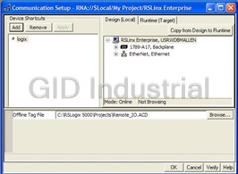


What they say about us
FANTASTIC RESOURCE
One of our top priorities is maintaining our business with precision, and we are constantly looking for affiliates that can help us achieve our goal. With the aid of GID Industrial, our obsolete product management has never been more efficient. They have been a great resource to our company, and have quickly become a go-to supplier on our list!
Bucher Emhart Glass
EXCELLENT SERVICE
With our strict fundamentals and high expectations, we were surprised when we came across GID Industrial and their competitive pricing. When we approached them with our issue, they were incredibly confident in being able to provide us with a seamless solution at the best price for us. GID Industrial quickly understood our needs and provided us with excellent service, as well as fully tested product to ensure what we received would be the right fit for our company.
Fuji
HARD TO FIND A BETTER PROVIDER
Our company provides services to aid in the manufacture of technological products, such as semiconductors and flat panel displays, and often searching for distributors of obsolete product we require can waste time and money. Finding GID Industrial proved to be a great asset to our company, with cost effective solutions and superior knowledge on all of their materials, it’d be hard to find a better provider of obsolete or hard to find products.
Applied Materials
CONSISTENTLY DELIVERS QUALITY SOLUTIONS
Over the years, the equipment used in our company becomes discontinued, but they’re still of great use to us and our customers. Once these products are no longer available through the manufacturer, finding a reliable, quick supplier is a necessity, and luckily for us, GID Industrial has provided the most trustworthy, quality solutions to our obsolete component needs.
Nidec Vamco
TERRIFIC RESOURCE
This company has been a terrific help to us (I work for Trican Well Service) in sourcing the Micron Ram Memory we needed for our Siemens computers. Great service! And great pricing! I know when the product is shipping and when it will arrive, all the way through the ordering process.
Trican Well Service
GO TO SOURCE
When I can't find an obsolete part, I first call GID and they'll come up with my parts every time. Great customer service and follow up as well. Scott emails me from time to time to touch base and see if we're having trouble finding something.....which is often with our 25 yr old equipment.
ConAgra Foods