

 Manufacturers
ALLEN BRADLEY 845D-SJDZ25BDCK2

Description
ENCODER, ABSOLUTE
Part Number
845D-SJDZ25BDCK2
Price
Request Quote
Manufacturer
ALLEN BRADLEY
Lead Time
Request Quote
Category
ENCODERS
Datasheet

Extracted Text
Encoders Contents General Information Quick Selection Guide ....................... page 6--2 Electrical Interface Guide .................... page 6--4 Technical Definitions and Terminology ......... page 6--5 AbsoluteEncoders Bulletin 842A Multi-Turn Magnetic ............. page 6--7 Bulletin 842D DeviceNett Magnetic ......... page 10--16 Bulletin 842HR Sine Cosine/Serial ........... page 6--10 Bulletin 845D Single-Turn ................... page 6--14 Bulletin 845G Single-Turn ................... page 6--18 Bulletin 845GM Single-Turn ................. page 6--23 Incremental Optical EncodersBulletin 844A & 844B Hollow Shaft ........... page 6--28 Bulletin 844D Hollow Shaft .................. page 6--31 Bulletin 845F with Integral Coupler ........... page 6--34 Bulletin 845H Size 25 ...................... page 6--37 Bulletin 845T Size 20 ....................... page 6--41 Digital Tachometer Bulletin 845PY (5PY Mounting) .............. page 6--44 Accessories Serial Parallel Adaptor ...................... page 6--46 SPA Card Holder .......................... page 6--46 Flexible Couplings ......................... page 6--47 Measuring Wheels ......................... page 6--48 Servo Clamps ............................. page 6--48 Pre-Wired Cable Assemblies ................ page 6--49 Mating Connectors ......................... page 6--52 Mounting Plates ........................... page 6--52 Differential Encoder Buffer Board ............ page 6--55 Indexes Cat. No. Index ............................. page 13--1 Comprehensive Product Index ............... page 14--1 Visitourwebsite:www.ab.com/catalogs. 6--1 Encoders QuickSelectionGuide 842A 842HR 844A&844B 844D 845D Specifications Multi-Turn Magnetic Hollow Shaft Incremental Hollow Shaft Incremental Single-Turn Absolute SineCosine/Serial Absolute • 24 bits (2048…8192 CPR • 1024 PPR • 10…2500 PPR • 360…16,384 PPR • 8…12 bits (256…1000 Resolution & 256…8192 revolutions) CPR) • 10…30V DC • 5--12V DC, or 7…12C DC • 5V DC, 12V DC, or • 5V DC, 10…30V DC, or • 5V DC or 8…24V DC PowerSupply 8…24V DC 5…26V DC • Synchronous Serial • Analog differential • Differential line driver • Differential line driver • 5V TTL Outputs Interface (SSI) • Digital RS--485 • NPN open collector • Push-Pull • Open collector • Hiperfacer compatible • 60 mm (2.36 in.) • 64 mm (2.5 in.) • 51 mm (2.0 in.) • 90 mm (3.5 in.) • 64 mm (2.5 in.) HousingSize(Dia.) • Up to 500 kHz • 200 kHz • 100 kHz • 200, 300, or 600 kHz • 16 K words/sec Frequency ResponseorData Rate • 6000 RPM • 6000 RPM • 3000 RPM • 3000 RPM • 5000 RPM ShaftSpeed • Metric servowith36or • Square flange • Integral flex mount • Three tether options & • Square flange Mounting 50 mm pilot • Hub Shaft anti-rotation pin • English servo • Radial connector • Radial connector • 18in (457mm) integral • Radial connector • Axial connector Connections cable • Radial cable • Radial connector • Terminal block • IP66 (IEC 529) • IP66 • IP40 (IEC 529) • NEMA 4, 13; IP66 • NEMA 4, 13; IP66 Protection • See page 6--7 • See page 6--10 • See page 6--28 • See page 6--31 • See page 6--14 AdditionalInfo 845F 845G 845GM 845H 845K Specifications Incremental with Integral Single-Turn Absolute Single-Turn Absolute Size25Incremental Size25Incremental Coupler • 1…5000 PPR • 8…15 bits (256--32,768 • 8…15 bits (256--32,768 • 1…5000 PPR • Up to 5000 PPR Resolution CPR) CPR) • 5V DC or 8…24V DC • 5V DC, 10…30V DC, or • 5V DC, 10…30V DC, or • 5V DC or 8…24V DC • 5V DC or 8…24V DC PowerSupply 8…24V DC 8…24V DC • Source • 5V TTL • 5V TTL • Source • Source Outputs • Sink w/pullup • Open collector • Open collector • Sink w/pullup • Sink • Differential line driver • Push-Pull • Push-Pull • Differential line driver • Differential line driver • Open collector • SSI • SSI • Open collector • Open collector • 64 mm (2.5 in.) • 64 mm (2.5 in.) • 51 mm (2.0 in.) • 64 mm (2.5 in.) • 64 mm (2.5 in.) HousingSize(Dia.) • 200 kHz • 16 Kwords/sec • 16 Kwords/sec • 200 kHz • 210 kHz Frequency ResponseorData Rate • 6000 RPM • 5000 RPM • 5000 RPM • 6000 RPM • 6000RPM ShaftSpeed • Standard coupler • Square flange • Square flange • Square flange • Square flange Mounting • High performance coupler • English servo • English servo • English servo • English servo • Axial connector • Axial connector • Radial connector • Axial connector • 24in pigtail cable Connections • Radial connector • Radial connector • Radial connector termination • Axial cable • Axial cable • Radial cable • Radial cable • NEMA 4, 13; IP66 • NEMA 4, 13; IP66 • NEMA 4, 13; IP66 • NEMA 4, 13; IP66 • NEMA 1 Protection • See page 6--34 • See page 6--18 • See page 6--23 • See page 6--37 • www.ab.com/catalogs AdditionalInfo Visitourwebsite:www.ab.com/catalogs. 6--2 Encoders QuickSelectionGuide 845P 845PY 845S 845T Specifications Size15Incremental Digital Tachometer IGBT DriveIncremental Size20Incremental (5PY Mounting) • 500 or 1000 PPR • 1…3000 PPR • Up to 5000 PPR • 1…3000 PPR Resolution • 5V DC • 5V DC, 11…20V DC or 24V DC • 5V DC and 8…24V DC • 5V DC, 11…20V DC or 24V DC PowerSupply • Differential line driver • Differential line driver • Differential line driver • Push-Pull Outputs • Differential line driver • 40 mm (1.59 in.) • 51 mm (2.0 in.) • 64 mm (2.5 in.) • 51 mm (2.0 in.) HousingSize(Dia.) • 100 kHz • 100 kHz • 100 kHz • 100 kHz Frequency ResponseorData Rate • 5000 RPM • 15000 RPM • 6000RPM • 15000 RPM ShaftSpeed • English servo • 5PY • Square flange • Square flange Mounting • English Servo • English servo • 18 in. (457 mm) integral cable • Radial connector • Axial connector & cable • Radial connector Connections • Radial cable • Radial connector & cable • Radial cable • NEMA 1 • NEMA 4, 13; IP66 • NEMA 4, 13; IP66 • NEMA 4, 13; IP66 Protection • www.ab.com/catalogs • See page 6--41 • www.ab.com/catalogs • See page 6--41 AdditionalInfo Accessories FlexibleCouplings MeasuringWheels ServoClamps CableAssemblies MatingConnectors • See page 6--47 • See page 6--48 • See page 6--48 • See page 6--49 • See page 6--52 AdditionalInfo BufferBoard SerialParallel ServoClamps MountingPlates Accessories Adaptor • See page 6--55 • See page 6--46 • See page 6--46 • See page 6--52 AdditionalInfo Visitourwebsite:www.ab.com/catalogs. 6--3 Encoders I/OtoEncoderSelectionGuide Accessories To use this selection guide,scan down be used in the application.The asterisk the appropriate pages in the catalog. the column ofthe inputcard ordevice (*)is used to representone character Some absolute encoders typically being used,then look in the column to in the catalog number.Complete the require an outputmodule to send a the rightfortypicalencoders thatcould encodercatalog numberby referring to latching signal. IncrementalEncoders AbsoluteEncoders Andselectoneofthese Ifyouhaveoneof Selectoneofthese Ifyouhaveoneofthese Selectoneofthese OutputModulesif theseInputDevices: Encoders: InputDevices: Encoders: necessary: 1395 DC Drive 845F--SJ*Z*4**Y** 1746--IG16 845D--SJ***4BD*** 1771--OG / OGD 1746--HSCE 845H--SJ***4**Y** 1771--IG 845D--SJ***4BN*** 1746--OG16 1746--HSTP1 845K--SA*Z*4**Y3 1771--IGD 845G--*3**HT**** 1756--M02AE 845M--***5LD***** 845GM--*3**HT***** 1756--HSC 1746--IG16 1771--IJ 845P--SHC14--**3 845D--SJ***4AG*** None Required 1771--QC 845PY--**--*--* 1771--IG 845G--*3G*HT***** 1771--VHSC 845T--**13E**--* 1771--IGD 845GM--*3G*HT***** 8200 CNC 845T--**43E**--* 842A with 842--SPA 8400 CNC 845T--**53E**--* 8600 CNC 844D--****1** 1746--ITV16 845D--SJ**25AG*** None Required 9 SERIES CNC 844D--****4** 1746--IV8,16,32 845G--*3G8HC***** IMC 110, 120 844A--**05D**** 1771--IQ, IQ16 845GM--*3G8HC***** IMC 121, 123 844B--**05D**** 1771--IV, IVN 842A with 842--SPA IMC S--CLASS 1756--IV16 MAX CONTROL 1794--IV16 1771--IK 845F--SJ*Z26**Y** 1746--ITV16 845D--SJ**25BD*** 1771--OV 845H--SJ**26**Y** 1746--IV8,16,32 845D--SJ**25BN*** 1746--OV 845K--SA*Z25**Y3 1771--IQ, IQ16 845G--*3B8HC***** 1756--OV16E 845T--**3****--C 1771--IV, IVN 845G--*3D8HC***** 1794--OV16 844A--**12C**** 1756--IV16 845GM--*3B8HC***** 844B--**12C**** 1794--IV16 845GM--*3D8HC***** 844D--****5** 1771--DE 845D--SJ***4A**** None Required 1336 PLUS 845S--**** 845G--*3**HT***** 1336 FORCE 845GM--*3**HT***** 1336 IMPACT 1771--DL 845D--SJ***5AGCW* None Required MICROLOGIX 845T--**33A**--* 845G--*3G8HC0256* 1000, 1200, 1500 845TK--*****--** 845GM--*3G8HC0256* 844D--****5** 844A--**12C**** 4100--AEC 842A--***** None Required 844B--**12C**** AMCI 7561 845G--*3*AHS***** 845GM--*3*AHS***** 1794--VHSC 845H--SJ**24 1394 845T--**53 1756--IBI16 845G--*3G8LC***** None Required 844D--****4** 845GM--*3G8LC****** 844A--**05D**** 845D--SJ**25AG 844B--**05D**** 1756--PLS 846--SJDA1CG--R3C None Required 1794--ID2 845H--SJ**26 1746--HSCE2 845T--**63 1746--ITB16 845G--*3*8HP***** 1771--OV 1756HSC 844D--****2** 1746--IB8, IB16, IB32 845GM--*3*8HP***** 1746--OV 1397 844A--**24D**** 1771--IQ, IQ16 1756--OV16E 844B--**24D**** 1771--IB, IBN 1794--OV16 1794--IB16 1747--L**C 845T--**31** 1756--IB16 1747--L**D MicroLogix 1000, 1200, 1500 1747L**E 845--BB-- 845F--SJ**14 845H--SJ**14 845K--SA**14 845P--SHC14--** 845T--**13 844D--****1** 844A--**05D**** (5V DC Supply) 844B--**05D**** 845F--**24 845H--SS**24 845K--SA**24 845T--**43 844D--****4** (12V DC Supply) Wire Single Ended Only (no complements) Visitourwebsite:www.ab.com/catalogs. 6--4 Encoders TechnicalDefinitionsandTerminology 5PY:A type ofanalog DC tachometer Decades:In BCD a decade is IP66(IEC529):Provides a degree of with a specific boltpattern. comprised of4 bits (1,2,4,8) protection againstdust,and water representing one decimalplace (units, projected in powerfuljets fromany AngularAcceleration:Therateof tens,hundreds,etc.). direction. change ofangularvelocity usually expressed in radians persecond Differential:In digitallogic terms a pair Load:A termused to describe the squared. ofoutputs exactly opposite 0,1,or180 device to which encodersignals are degrees outofphase. applied. AngularMisalignment:The maximum amountofangle between the coupled DifferentialLineDriver:Atypeof MaximumWorkingTemperature:A shafts. outputdriverusing two signallines per maximumtemperature allowed for encoderchannel.When used with a operation formostapplications.Some Axial:The direction parallelto the differentialline receiver,longercable specifications may notbe met.Also see encodershaft. lengths and highernoise immunity can “Operating Temperature.” be provided. AxialCompliance:The maximum MaximumWorkingSpeed:A amountofmachine shaftend play. DutyCycle:The ratio ofthe logic “1” maximumspeed allowed foroperation levelto the totalperiod ofone cycle. formostapplications.Shaftloading AxialLoad:The maximumamountof mustbe minimized.Some force thatmay be applied to an encoder EndPlay:The amountofaxialshaft specifications may notbe met.See also shaftin a direction parallelto the shaft. movementwith a specified amountof “Operating Speed.” axialload applied. BlindShaft:A hollow shaftencoder MomentofInertia:The sumofthe which is covered on one end so thatthe Flange:A square mounting products formed by multiplying the accepted shaftcannotexceed a configuration forrotary encoders and mass ofeach elementofa figure by the maximumlength.See also “Hollow resolvers. square ofits distance froman axis. Shaft”and “Through Shaft.” FrequencyResponse:The maximum NEMAType1:Type 1 enclosures are Binary:A numbersystemusing 2 as its frequency atwhich allparameters are intended to provide protection against base (1,2,4,8,16,32,...). stillin specification. incidentalcontactwith dirt,dust,lint, fibers,and othernonliquid BinaryCodedDecimal(BCD):A GrayCode:A binary code in which contaminants. numbersystemwhere decimalnumbers only one bitofthe binary word changes 0 through 9 are represented by 4 binary foreach sequentialnumberorposition. NEMAType4:Type 4 enclosures are bits (8,4,2,1). intended forindoororoutdooruse HeavyDuty:Encoders with higher primarily to provide a degree of Bit:An abbreviation forbinary digit. shaftloading characteristics are protection againstwindblown dustand considered heavy duty. rain,splashing waterand hose directed Channel:An incrementalencoder water.They are notintended to provide outputsignal.A dualchannelencoder HighPerformance:Encoders with high protection againstconditions such as has two outputs. frequency response and resolution are internalcondensation orinternalicing. considered high performance. CountsPerTurn:Sometimes referred Nosepiece:The housing thatholds the to as Pulses PerRevolution (PPR),the HollowShaft:A shaftless encoder shaft,bearings,and shaftseal. totalnumberofpositions in 360 design which mounts on the shaftofa degrees ofshaftrotation. connected device such as a motor.See NullVoltage:The residualvoltage also “Blind Shaft”and “Through Shaft.” remaining when the in-phase CurrentSinking:An outputtype where componentofthe outputvoltage is signalcurrentflows fromthe load into Impedances:Impedances,expressed zero. the encoder. in ohms,are usually specified in rectangularformas R + jX where R is OperatingSpeed:The maximumshaft CurrentSourcing:An outputtype the sumofthe DC and AC resistive RPMallowed atwhich allspecifications where signalcurrentflows fromthe components and X is the reactive are met.See also “MaximumWorking encoderinto the load. component. Speed.” Data:Factualmeasurementinformation Index:An outputsignal,also known as OperatingTemperature:The transmitted by an encodereitherin a zero marker,which is produced once maximumtemperature allowed atwhich parallelorserialform. perrevolution.Itis used to identify a allspecifications are met. home position ora resetpoint. ParallelMisalignment:The maximum InputCurrent:The currentrequired to amountofdistance between the center powerthe internalcircuitry ofthe lines ofthe coupled shafts. encoder. Visitourwebsite:www.ab.com/catalogs. 6--5 Encoders TechnicalDefinitionsandTerminology PulsesPerRevolution(PPR):See Servo:A circularmounting StartingTorque:The torque required counts perturn. configuration thatallows forrotation of to starta shaftrotating,typically the encoderforpurposes ofalignment. measured in inch-ounces. Push-Pull:A type ofsingle-ended Also a common termfora smallelectric outputdrivercapable ofsinking and Symmetry:The ratio ofthe logic “1” motor. sourcing current.Also known as levelto the totalperiod ofone cycle. Totem-Pole. ShaftLoading:The maximumamount SynchronousSerialInterfaceorSSI: offorce thatmay be applied to an Quadrature:Separation in phase by A serialcommunication protocoloften encodershafttypically expressed in 90°.Used on incrementalencoders to used to translate parallelabsolute pounds (Newtons). denote the direction ofmotion. encoderdata.Advantages ofSSIover ShaftRunout:The amountofradial parallelwiring include reduced wire Radial:The direction perpendicularto movementwhen spinning. countand betternoise immunity. the encodershaft. Shock:A transientmotion which is ThroughShaft:A hollow shaftencoder RadialLoad:The maximumamountof capable ofexciting mechanical which is open on both ends so thatthe force thatmay be applied to an encoder resonances. accepted shaftlength is unlimited.For shaftin a perpendiculardirection. example,a through shaftencoder Single-Ended:An outputreferenced to allows a motorshaftto protrude through RadialPlay:The amountofshaftradial common which uses only one signal it.See also “Blind Shaft”and “Hollow movementwith specified radialload. line fordata transmission. Shaft.” Radian:An arc in any circle,equalin Size15:Encoders with a nominal TransformationRatio:The ratio ofthe length to the radius ofthe same circle. diameterof1.5 inches (1.625 inch outputvoltage to the inputvoltage when encoders are also classified as size 15). the outputis atmaximumcoupling. Resolution:The measure ofthe smallestchange ofinputthatthe Size20:Encoders with a nominal Vibration:The periodic change in encodercan detect. diameterof2.0 inches. displacementwith respectto a fixed reference. RunningTorque:The torque required Size25:Encoders with a nominal to keep a shaftrotating atconstant diameterof2.5 inches. ZeroReference:An outputsignal velocity,typically measured in which is produced once perrevolution. inch-ounces. SlewSpeed:The maximumvelocity an Itis used to identify a home position or encodermay be operated without a resetpoint. Sensitivity:The outputvoltage physicaldamage to the unit. expressed as a function ofthe shaft angle in millivolts/degree. Visitourwebsite:www.ab.com/catalogs. 6--6 Encoders Bulletin842AAbsoluteMulti-TurnMagneticEncoders SynchronousSerial Interface Specifications CE Marked for all applicable directives. Certifications Electrical Code Format Gray or Natural Binary Code Direction CW or CCW Symmetry 40…60% Operating Voltage 10…30V DC Power Supply 30 mA @ 24V No.ofSteps,Max. 8192 No. of Revolutions, Max. 8192 SSI Position Forming Time 0.15 msec Description Power-Up Delay 1050 msec Bulletin 842A is a 25-bitabsolute Clock+,Clock --,Data +,Data -- Synchronous Serial Interface (SSI) multi-turn shaftencoder.Itcan provide CW/CCW “L”active(L= 0--1.5V, H = 3.0 -- V ) s up to maximumof8192 pulses perturn Reset Via covered rear button or reset pin ora maximumof8192 turns.Ithas SSI outputs to reduce cable costs. Mechanical The 842A can be interfaced in several 5 2 Angular Acceleration 5x 10 radians/sec ways: 2 --4 2 Moment of Inertia 35 gcm (5.0 x 10 oz-in-sec ) S 1734--SSISynchronous Serial Shaft Operating Speed, Max. (RPM) 6000 RPM at max shaft loading Interface Absolute EncoderModule Starting Torque 2.5 Ncm (3.5 oz-in) S 842--SPA and 842--CH which Shaft Loading Axial11lb(50 N) converts SSIto paralleldata Radial 67 lb (300 N) S 4100--AEC which converts SSIto A quad B data to interface with 1394 Environmental GMC/GMC Turbo and S Class Material Aluminum housing Compactmotion controllers (see Operating Temperature [C (F)] --20…85_ (--4…+185_) publication 4100--AEC--1.1) Storage Temperature [C (F)] --40…100_ (--40…+212_) S SLC inputmodule AMCI7561 which Relative Humidity 98% noncondensing inputs SSIdata directly into the Enclosure Type Rating NEMA Type 4, 13; IP67 (IEC 529): Static Shaft module (see Encompass partner Shock 100 g/6 msec AMCI). Vibration 20 g/10…2000 Hz S PLC—AMCI7761H Weight [g (oz)] 0.5 (18) Synchronous SerialInterface orSSI provides many advantages over Typical Applications Accessories traditionalparallelwiring.SSIprovides 25 bitresolution over5 wires rather S Steelmills Description PageNumber than the usual24 wires.The use ofSSI S Overhead cranes Serial Parallel technology in the Bulletin 842A 6--46 Adaptor Board provides the following customer S Punch press benefits: Flexible Couplings 6--47 S Transferlines S Greatly reduced wiring costand Measuring Wheels 6--48 S Oilrigs complexity Servo Clamps 6--48 S Wind mills S Greatly improved noise immunity Pre-Wired Cables 6--49 achieved via differential S Machine Tools communication format Mating Connectors 6--52 S Packaging S Simplified startup Mounting Plates 6--52 S Choice ofgray code ornaturalbinary formats Visitourwebsite:www.ab.com/catalogs. 6--7 Encoders Bulletin842AAbsoluteMulti-TurnMagneticEncoders SynchronousSerial Interface ProductSelection 842A — 31 G B a b c a b c Mounting Configuration CodeType Resolution Code Description Code Description Pulsesper Numberof Code Revolution Revolutions Servo Mount 10 mm Shaft G Gray Code 31 36 mm Pilot A 8192 2048 N Natural Binary Servo Mount 6 mm Shaft B 4096 4096 56 50 mm Pilot C 2048 8192 D 4096 512 E 4096 256 Electrical Connections The 842A comes with an M23 connector.Orderthe mating connector separately. Function PinNumber DC Return 1 Data + 2 Clock + 3 DC+ Input 8 Data -- 10 Clock -- 11 CW/CCW 12 Reset 9 Typical Application 842--SPA Adaptor Board 845FC--*--* Coupling Controller 845--SC Servo Clamp Parallel 845--CA--G--** 842--CH Wiring Cable Assembly Cardholder 842A--**** Encoder Visitourwebsite:www.ab.com/catalogs. 6--8 Encoders Bulletin842AAbsoluteMulti-TurnMagneticEncoders SynchronousSerial Interface ApproximateDimensions[mm(in.)] 60 (2.36) 3 (0.12) 42±0.1 3 (0.12) (1.65) 4 (0.16) 34 (1.34) 13 (0.51) Covered Reset Button ∅58 51.5 (2.28) (2.03) 66 ∅24 ∅59.5 (2.60) 120_ (0.94) (2.34) 49.94/49.98 Typ 13.5 (1.966/1.967) M4 (0.53) 3Plcs 7 (0.28) deep 5.98/5.99 24 (0.235/0.236) 27.8 (0.94) (1.09) 9.0/11.0 (0.35/0.43) 25_ Bulletin842A--56** 60 (2.36) 48±0.1 3 (0.12) (1.89) 3 (0.12) 34 9.98/9.99 (1.34) 13 (0.392/0.393) (0.51) Covered Reset Button ∅59.5 35.94/35.98 (2.34) ∅24 (1.415/1.416) 66 (0.94) 120_ ∅53.8 (2.60) 13.5 Typ (2.12) M4 (0.53) 3Plcs 7 (0.28) deep 8.8/9.2 24 10 (0.34/0.37) (0.94) 18 (0.39) (0.71) 27.8 25_ (1.09) 18/20 (0.71/0.79) Bulletin842A--31** FlexibleShaftCouplings ATTENTION Activating the zero ATTENTION Rigidly coupling the reset results in a encoder shaft to Angle change of position the machine shaft reading. This can will cause a failure cause unexpected in either the Parallel motion which could bearings of the Off-Set encoder or the result in damage to the product, bearings of the machine shaft. equipment, or personal injury. Visitourwebsite:www.ab.com/catalogs. 6--9 Encoders Bulletin842HRSineCosine/SerialEncoders Size25, High Resolution AuxiliaryServo Feedback Specifications Certifications CE Marked for all applicable directives Electrical # of sine/cosine cycles per revolution 1,024 Code format for absolute position value Binary Code direction with clockwise rotation viewed Increasing from shaft end # of steps per revolution (Single 842HR--S) 32,768 # of revolutions (Multi 842HR--M) 4,096 Error limits for the digital absolute value via ±90 angular seconds RS 485 Description Error limits in evaluating the 1,024 signals, ±45 singular seconds integral non-linearity Bulletin 842HR is a 15-bitserial/sine Non-linearity within a sine/cosine period, ±7 angular seconds cosine encoder.Targeted forhigh differential non-linearity performance digitalservo drive systems thatrequire absolute feedback for Output frequency for sine/cosine signals 0…200 kHz position controland high resolution Operating Voltage Range 7…12V, 5…12V incrementalfeedback forspeed control. Max. Operating Current, no load RockwellAutomation sine cosine high 5…12 V Supply 180 mA 7…12 V Supply 80 mA performance encoders provide commutation,speed regulation and Available Memory on EEPROM 128 bytes position controlallin one device. Interface Signals Absolute position values ofup to 15 bit Process data channel = SIN, REFSIN, COS, Analog, differential combined with incrementalresolution REFCOS up to 2 million counts perturn. Parameter channel = RS 485 Digital Mechanical Features 5 2 Angular Acceleration, Max. 5x 10 rad/sec S Absolute feedback forposition Shaft Operating Speed, Max. (RPM) 6,000 control Torque to Operate [N•m(lb•in)] 0.024 (0.212) max. S High resolution Incrementalfeedback Starting Torque, Max. 0.035 N•m (0.309 lb•in) forspeed control Shaft Loading Radial 35 lb, Axial 40 lb S Commutation 9 Life of Ball Bearings 3.6 x 10 rotations S Sine cosine differentialinterface Environmental S DigitalbidirectionalRS-485 interface Material Aluminum housing R S Compatible with Hiperface interface Operating Temperature [C (F)] --20…85_ (--4…+185_) S Internaldiagnostic functions Storage Temperature [C (F)] --30…+90_ (--22…+194_) Relative Humidity 90% Typical Applications Shock 30 g/11 ms Compatible with a variety ofmotor Vibration 20 g/10…2kHz controlproducts including KinetixR Enclosure Type Rating IP66 (IEC60529) drives and the Allen-Bradley Weight [g (oz)] 481 g (17 oz) Guardmastert MSR 57 safe speed EMC DIN EN61000--6--2 monitoring relay,the 842HR is a flexible DIN 61000--6--3 solution fora wide range ofindustrial applications. Inrushcurrentwith5…12Vsupply canbeas highas 1Amp Ifapplyingtheelectronic typelabel,inconnectionwithnumeric controllers,attentionshouldbepaid S Packing machines toPatentEP425912B2.Applicationoftheelectronic typelabelinconnectionwithspeedregulation is exempt. S Robotics Condensationnotpermissible ToDIN EN 60068--2--27 S Printing machines ToDIN EN 60068--2--6 Withmatingconnector inserted S Rotary table positioning Visitourwebsite:www.ab.com/catalogs. 6--10 Encoders Bulletin842HRSineCosine/SerialEncoders Size25, High Resolution AuxiliaryServo Feedback ProductSelection 842HR — S J DZ 1 15FWY 2 a b c d a b C No. ofTurns Mounting Configuration (Note) PowerSupply Code Description Code Description Code Description S Single-turn (1 turn) DZ Square Flange, 3/8 in. solid shaft 1 5…12V DC M Multi-turn (4096 turns) Square Flange, 3/8 in. solid shaft with 2 7…12V DC DN flat A1 Hub shaft, 15 mm blind hollow shaft d A2 Hub shaft, 1/2 in. blind hollow shaft Connection Options A3 Hub shaft, 12 mm blind hollow shaft Code Description A4 Hub shaft, 10 mm blind hollow shaft 2 MS 10-pin A5 Hub shaft, 3/8 in. blind hollow shaft D M23 17-pin A6 Hub shaft, 8 mm blind hollow shaft A7 Hub shaft, 1/4 in. blind hollow shaft A8 Hub shaft, 6 mm blind hollow shaft Note:Hubshaftunits aresuppliedwith 15 mmblindhollowshaft.Forshaftbores smallerthan15mm,ashaftinsertis suppliedhavingthecorrectID. OutputTermination:M2317-Pin OutputTermination:MS10-Pin PinNo. Function Explanation WireColor PinNo. Function WireColor 1 SINE Process Data Channel Black A +VS Red 2 REFSINE Process Data Channel White/Black B Common Blue 3 COSINE Process Data Channel Red C Ref SIN Brown 4 REFCOSINE Process Data Channel White/Red D Ref COS Black 5 Data + RS-485 parameter channel Green E Data + Grey 6 Data -- RS-485 parameter channel White/Green F Data -- Green 9 DC + Input 5V Supply Voltage Grey G SIN White 10 DC Return Ground Connection White/Grey H COS Pink 11 DC + Input 9V Supply Voltage Orange I Not Used 13 N.C. J Case Case 14 N.C. 15 N.C. 16 N.C. 17 N.C. 7 CASE Case Ground Brown 8 N.C. 12 DC Return Ground Connection Pin 12 internally tied to pin 10 Visitourwebsite:www.ab.com/catalogs. 6--11 Encoders Bulletin842HRSineCosine/SerialEncoders Size25, High Resolution AuxiliaryServo Feedback ApproximateDimensions[mm(in.)] 63.4 (2.5) 8--32 UNC--28 0.18 (9.57) min. 46.4 (1.8) 3 places 120° apart on a 47.63 (1.875) B.C. 31.75 (1.25) 31.74 (1.24) 19.1 (0.75) 68.4 (2.7) 66.5 52.3 (2.62) (2.06) 9.51 (0.3746) 8.71 9.51 (0.3744) (0.34) 5.3 (0.21) dia. 7.6 52.3 (2.06) 4places 7.6 (0.30) 29.6 (0.30) (1.16) 9.51 (0.3746) 66.5 (2.62) 9.51 (0.3744) 29.6 (1.16) Solid Shaft with Flat SquareFlange, Solid Shaft 63.0 (2.48) 20° 3.3 15 (0.59) is max. bore size (0.13) smaller bores require collets 32.5 68.4 (2.7) (1.28) 72.0 (2.83) 1.97 (0.08) 75.5 93.0 (3.0) (3.7) Hub Shaft Visitourwebsite:www.ab.com/catalogs. 6--12 Encoders Bulletin842HRSineCosine/SerialEncoders Size25, High Resolution AuxiliaryServo Feedback Description Accessories ApproximateDimensions [mm(in.)] High performance flexible couplings are Description Cat.No. used to connecttwo shafts,and help to M23 17-Pin Cables 2090--XXNFMF--Sxx HighPerformanceFlexibleCoupling reduce the effects ofmisalignment between the shafts.Flexible couplings MS 10-Pin Cables 842HR--CA--2--yy are offered in the high performance Flexible Coupling 845--FC--x--x version,with nonconductive inserts. X They are ofthe flexible curved beam 2090--XXNFMF--Sxx helicaltype with clamping screw atboth Pre-wired cable to a M23 DIN 17-pin ends. Y Z connectorforthe encoder.The other Specifications end ofthe cable is flying leads. BoreSizeCodeLetter Dimension Parallel Offset 0.51 mm (0.02 in.) max. Code A B C R T xx=CableLength Angular Offset 10° max. 6.4 9.5 12.7 6 10 X 01 1m (0.25) (0.375) (0.50) Axial Compliance 1.58 mm (0.06 in.) max. 02 2m Y 30.56 (1.20) Dia. Aluminum with a fiberglass 03 3m Construction Z 32 (1.25) Long insert 04 4m Available cat.nos.forthis encoder: 05 5m ATTENTION The shielded 845--FC--B--B 07 7m cables, output 845--FC--B--C 09 9m devices, and power 845--FC--B--R supplies must be 12 12 m 845--FC--B--T properly grounded. 845--FC--A--B 15 15 m 845--FC--R--B All National Electric 20 20 m Code and 25 25 m applicable local ProductSelection 30 30 m codes and ordinances must be 845 — FC —B—B Note:Consultmanufacturer’s drivemanual observed when formaximumrecommendedcablelength. a b wiring the system. 842HR--CA--2--yy FlexibleShaftCouplings Pre-wiredcabletoaMS10-pinconnector a for the encoder. The other end of the Angle cable is flying leads. SmallestBoreDiameter Code Description yy=CableLength A 1/4 inch 01 1m Parallel B 3/8 inch Off-Set 03 3m R 6mm 05 5m T 10 mm 10 10 m ATTENTION Rigidly coupling the 20 20 m encoder shaft to b 30 30 m the machine shaft LargestBoreDiameter will causea FlexibleCouplings Code Description failure in either the A 1/4 inch bearings of the encoder or the B 3/8 inch bearings of the C 1/2 inch machine shaft. R 6mm T 10 mm Visitourwebsite:www.ab.com/catalogs. 6--13 Encoders Bulletin845DAbsoluteEncoders Single-Turn, Size25 Specifications Electrical Code Format Binary Coded Decimal (BCD) Gray Code Natural Binary Resolution (Gray and 256 CPR (8 bit); 512 CPR (9 bit) Natural Binary): 1024 CPR (10 bit) (BCD): 360 CPR (10 bit); 1000 CPR (12 bit) Accuracy ±1bit Response Frequency 16 K words/sec EnglishServoMount Power Supply Determined by Cat. No.: 5V DC±5% @ 400 mA max. 845D--SJHZ14BDCK2 8…24V DC @ 400 mA max. Output Drives NPN current sink = 16 mA Description Output Logic Parallel BCD, GRAY, or NAT BIN: Logic “0” = 0.0…0.6V DC Logic “1” = 3.5…5.0V DC (TTL) The Bulletin 845D is a heavy duty, Logic “1” = 24V DC maximum NEMA Type 4 single-turn absolute (Open collector) position encoderthatdigitizes shaft Latch Command Optional with BCD and NAT BIN only: Logic “0” = outputs active angle position into one ofa numberof (DC common) absolute code formats.The absolute Logic “1” = outputs latched encoderhas a unique digitaloutputfor (+DC or open) each shaftposition.The use ofabsolute Code Direction Field selectable for increasing counts (CW or CCW) encoders assures thattrue position is Reset Reset position value to zero (Natural Binary and BCD) or max. (Gray always available,regardless ofpower Code). Only with shaft stationary. interruptions to the system. Mechanical The Bulletin 845D provides improved Starting Torque 2.5 Ncm typical [3.5 in.-oz] accuracy,increased operating speed and high noise immunity over Running Torque 2.5 Ncm typical [3.5 in.-oz] competitive units.The 845D is housed Shaft Loading Axial 89 N [20 lbs]; Radial 178 N [40 lbs] inasize25NEMAType4enclosure to Shaft Size 6 mm, 10 mm, 1/4 in., 3/8 in. diameter meetthe demands oftoday’s industrial 2 2 environment. Moment of Inertia 54 g--cm (0.3 oz-in. ) Slew Speed 5000 RPM Features Environmental S Absolute Gray Code,NaturalBinary Housing NEMA Type 4, IP66 (IEC 529); NEMA Type 4X on selected models orBCD output Operating Temperature [C (F)] 0…+85° (+32…+185° ) S Optionallatch command inputfor Storage Temperature [C (F)] --25…+90° (--13…+194°) discrete I/O Humidity 98%, noncondensing S Optional5V or8…24V DC power Shock 50 g (11 ms duration) requirements Vibration 20g(58…150 Hz), 1.5 mm displacement (10…58 Hz) S 85_C (185_F)operating temperature Weight [kg (lbs)] 0.91 (2) S Electronic zero setpin S Field-selectable direction control Accessories S CE Marked forallapplicable Description PageNumber directives Flexible Couplings 6--47 Measuring Wheels 6--48 Servo Clamps 6--48 Pre-Wired Cables 6--49 Mating Connectors 6--52 Mounting Plates 6--52 Visitourwebsite:www.ab.com/catalogs. 6--14 Encoders Bulletin845DAbsoluteEncoders Single-Turn, Size25 ProductSelection 845D — S J D Z 1 4 B D CK 4 a b c d e f g h i a d h NEMARating PowerSupplyOptions Resolution Code Description Code Description Code Description J NEMA 4 1 5V DC±5% CW 256 Gray Code DW 512 X NEMA 4X 2 8…24V DC Unregulated or Natural Binary FW 1024 b e CK 360 Binary Coded Mounting Configuration OutputConfiguration Decimal CN 1000 Code Description Code Description i D Square Flange 4 5V DC TTL Compatible ConnectorOptions E 70 mm Diameter Flange NPN Open Collector 5 24V DC Max. F 90 mm Diameter Flange Code Description G Metric Servo48mm B.C. Axial Connector (End) f 1 without Mate H English Servo Latch Options 2 Radial Connector (Side) without Mate J Metric Servo42mm B.C. Code Description Axial Connector (End) 4 c with Mate A No Latch Radial Connector (Side) Latch (Sink Output ShaftOptions 5 B with Mate Module Compatible) Code Description A 6mm Diameter g B 10 mm Diameter OutputCodeType C 1/4 in. Diameter Code Description Z 3/8 in. Diameter D Binary Coded Decimal K 6mm w/Flat G Gray Code L 10 mm w/Flat N Natural Binary M 1/4 in. w/Flat N 3/8 in. w/Flat Availablewithsquareflangemountingconfigurationonly. This optionnotavailablewithLatchOptions code:“B.” Theseoptions notavailablewithOutputCodeTypecode:“D.” Theseoptions notavailablewithOutputCodeTypecode:“G” &“N.” Visitourwebsite:www.ab.com/catalogs. 6--15 Encoders Bulletin845DAbsoluteEncoders Single-Turn, Size25 Electrical Connections Function Pin GrayCode NaturalBinary BCD(8421) 0 A G(0) 2 1 1 B G(1) 2 2 2 C G(2) 2 4 3 D G(3) 2 8 4 E G(4) 2 10 5 F G(5) 2 20 6 G G(6) 2 40 7 H G(7) 2 80 8 J G(8) 2 100 9 K G(9) 2 200 L MSB Complement Not Used 400 M Not Used Not Used 800 N Not Used Not Used Not Used P Not Used Not Used Not Used R Not Used Direction Control Direction Control S Reset Reset Reset T DC Return DC Return DC Return U Not Used Latch Control Latch Control V DC+ Input DC+ Input DC+ Input GrayCode(parallelonly) Binary and BCD position value to zero. Direction Pin Connecting the ResetPin to +DC will Counterclockwise rotation ofthe shaft The Direction Pin can change function resetGray Code position value to willproduce increasing counts.For with code type.In paralleltype Gray maximum(e.g.,255,511,1023,etc.)if increasing counts with a clockwise Code encoders,its function is Most MSBC is used,to zero ifMSB is used. rotation,use the MostSignificantBit significantBitComplementorMSBC for The resetfunction requires a ComplementPin instead ofthe Most short.In NaturalBinary and Binary connection to +DC for0.1 seconds or SignificantBitPin.See Electrical Coded Decimalencoders,its function is longer. Connection table forpin designation. Direction Control. ATTENTION Activating the ATTENTION For parallel gray Direction Control Reset Pin results in code: connecting NaturalBinaryandBCD a change of the MSB or MSBC A logic “1”(+DC oropen)on the position reading. to +DC will result in direction controlpin willproduce This can cause permanent damage increasing counts with a counter- unexpected motion to the encoder. clockwise rotation ofthe shaft.A logic which could result “0”(DC common)on the direction in damage to the controlpin willproduce increasing ResetPin counts with a clockwise rotation ofthe product, The shaftmustbe stationary before shaft. equipment, or using the resetfunction.Connecting the personal injury. ResetPin to +DC willresetNatural Rotationis viewedfromtheendoftheencoder shaft. Visitourwebsite:www.ab.com/catalogs. 6--16 Encoders Bulletin845DAbsoluteEncoders Single-Turn, Size25 ApproximateDimensions[mm(in.)] 58.42 58.42 (2.30) (2.30) Axial Mount Axial Mount Connector Connector Connector PT02E14--19P (023) Connector PT02E14--19P (023) 74.93 74.93 Radial Mount Radial Mount (2.95) (2.95) 2.54 Connector Connector (0.10) 2.54 (0.10) 6.35 (0.25) 7.62 (0.30) 7.62 (0.30) See Table Below 22.86/21.59 22.86/21.59(0.90/0.85) (0.90/0.85) 31.75 See Table Below 58.67 (1.25) Dia. 31.75 (2.31) Dia. 63.50 (1.25) Dia. (2.50) Dia. 26.21(1.032) 5 (0.21) Dia.—4 Mtg. Holes 10--32 UNC-2B X 9.6 (0.38) Deep 26.21 on a 47.6 (1.875) Dia. Bolt Circle, (1.032) 52.40 3 Places—120° Apart 10--32 UNC-2B x 9.6 (0.38) Deep (2.063) on a 47.6 (1.875) Dia. Bolt Circle, 3 Places—120° Apart 52.40 65.0 (2.063) (2.56) Dia. 66.5 (2.62) Sq. SquareFlangeMount EnglishServoMount Connector Connector PT02E14--19P (023) 58.42 58.42 58.42 58.42 PT02E14--19P (023) (2.30) (2.30) Axial (2.30) (2.30) Axial Mount Axial Mount Mount Axial Mount Connector Connector Connector Connector Radial Radial Mount 74.93 Mount 74.93 Connector (2.95) Connector (2.95) 79.7 79.7 (3.13) 2.54 2.54 Radial Radial 3.05 (0.10) (0.10) Mount Mount 3.05 (0.12) 7.62 7.62 Connector Connector (0.30) (0.30) 20.0 20.0 6.35 20.0 6.35 See Table See Table (0.79) (0.79) (0.25) (0.79) Below (0.25) Below 31.75 31.75 58.67 58.67 (1.25) Dia. (1.25) Dia. See 20.0 See Table Below (2.31) 63.5 63.5 (2.31) Table (0.79) 31.75 31.75 Dia. (2.5) (2.5) Dia. Below (1.25) Dia. (1.25) Dia. Dia. Dia. M4 x 5.0 Deep on a 70.0 Dia. M3 x 5.0 Deep on a Bolt Circle, 4 Places—90° 48.0 Dia. Bolt Circle 3 Places—120° Apart Apart M4 x 5.0 Deep on a M4 x 5.0 Deep on a 42.0 Dia. Bolt Circle 64.0 Dia. Bolt 3 Places—120° Apart 70.0 90.0 65.0 Circle, 4 Places— 65.0 (2.76) Dia. (3.54) Dia. 90° Apart (2.56) Dia. (2.56) Dia. Metric FlangeMount Metric ServoMount 19.05 ShaftDiameterOptions FlatDimensions (0.75) Code ShaftDiameter Code Dimension“A” A AorK 6 mm +0.00 mm, --0.013 mm K 5.3 mm (0.21 in.) BorL 10 mm +0.00 mm, --0.013 mm ShaftwithFlatOption L 9.1 mm (0.36 in.) Cor M 6.35(0.2499 ) +0.0000, --0.0005 M 5.5 mm (0.22 in.) Zor N 9.52 (0.3749) +0.0000, --0.0005 N 8.6 mm (0.34 in.) Visitourwebsite:www.ab.com/catalogs. 6--17 Encoders Bulletin845GAbsoluteEncoders Single-Turn, Size25 Specifications Electrical Code Format Binary Coded Decimal (parallel only) Grey code or natural binary (parallel or SSI) Resolution Counts per Rev. (CPR) 256 CPR (8 bit) 2048 CPR (11 bit) 360 CPR (9 or 10 bit) 4096 CPR (12 bit) 512 CPR (9 bit) 8192 CPR (13 bit) 1000 CPR (12 bit BCD) 16384 CPR (14 bit) 1024 CPR (10 bit) 32768 CPR (15 bit) Accuracy ±1bit Response Frequency 16 K words/sec EnglishServoMount 845G--S3G5HC1024R Power Supply Determined by Cat. No: 5V DC±5% @ 150 mA max. 8…24V DC @ 150 mA max. 10…30V DC @ 150 mA max. Description Output Drives 16 mA Bulletin 845G is a heavy duty NEMA Output Logic Parallel Grey, natural binary or binary coded decimal (BCD) Type 4 and 13 single-turn absolute Logic “0” = 0.0…0.6V DC encoderthatdigitizes shaftposition. Logic “1” = 3.5…5V DC (TTL) The absolute encoderhas a unique Logic “1” = 24V DC maximum (Open Collector) digitaloutputforeach shaftposition. SSI RS--422 compatible The use ofabsolute encoders assures thattrue position is available, Latch Command Standard with natural binary and BCD regardless ofpowerinterruptions. Logic “0” = outputs active (DC common) Logic “1” = outputs latched (+DC or open) Code Direction Field selectable for increasing counts (CW or CCW) Features Reset Reset position value to zero (natural binary and BCD) or max. (grey S Absolute grey code,naturalbinary or code). Only with shaft stationary. binary coded decimal(BCD) Mechanical S 8--…15--bitresolution (256…32,768) Starting Torque 0.025 N·m [3.5 in.--oz.]Typical S Open collector,TTL,push-pullorSSI Running Torque 0.025 N·m [3.5 in.--oz.]Typical outputs Shaft Loading Axial 89 N [20 lbs]; Radial 178 N [40 lbs] S Low orhigh true outputoptional Shaft Dimensions 9.517 mm [3/8 inch] diameter w/flat S NEMA Type 4 and 13 2 S Reverse polarity protection Moment of Inertia 0.08 oz.--in. max. Slew Speed S 85°C operating temperature 5000 RPM S CE Marked forallapplicable Environmental directives Enclosure Type Rating NEMA Type 4, 13, IP66 (IEC 529) Operating Temperature [C (F)] 0…+85° (+32°…+185°) Storage Temperature [C (F)] --40…+100° (--40…+212°) Working Temperature [C (F)] --20…+85° (--4…+185°), max. Relative Humidity 98%, noncondensing Shock 50 g (11 ms duration) Vibration 20g(58…150 Hz), 1.5 mm displacement (10…58 Hz) Weight [kg (lbs)] 0.91 (2) Accessories Description Cat.No. Mating Pre-Wired Connector Cable No.ofPins High Performance 845--FC---- Flexible Coupling 12 845--12P 845--CA--G-- Measuring Wheels 845--MW--A-- 17 845--17P 845--CA--H-- Servo Clamps 845--SC 19 845--SCD 845--CA--D-- For additional information, see the Accessories section on pages 6--46...6--55. Visitourwebsite:www.ab.com/catalogs. 6--18 Encoders Bulletin845GAbsoluteEncoders Single-Turn, Size25 ProductSelection 845G — F3 G 8 H C 1024 R a b c d e f g a e g Mounting Configuration OutputConfiguration ConnectorOptions Code Description Code Description Code Description F Square Flange NPN Open Collector A Axial 19-Pin C 24V DC Max S English Servo R Radial 19-Pin P Push-Pull (7272) S Axial 17-pin S SSI Output b T Axial 12-Pin T 5V DC TTL NPN U Radial 12-Pin OutputCodeType f Code Description Resolution B Natural Binary D Binary Coded Decimal Code Description G Grey Code 0256 8 bit/0…255 0360 9or10bit/0…359¡ c 0512 9 bit/0…511 1000 12 bit/0…999 BCD only PowerSupply 1024 10 bit/0…1023 Code Description 2048 11 bit/0…2047 5 5V DC±5% 4096 12 bit/0…4095 8 8…24V DC 8192 13 bit/0…8191 A 10…30V DC 016K 14 bit/0…16,383 032K 15 bit/0…32,767 d OutputLogic Code Description H High True L Low True Latch control available with natural binary and binary coded decimal (BCD) only. BCD output available in 0360 and 1000 resolutions only. Not available with SSI output. 10…30V DC power supply may only be ordered together with either push-pull or SSI output. Not available with push-pull output. Output logic inverted. Not available with BCD. Latch not available. Excess 76 used for 9 bit grey code. BCD is 10 bit. Only available with SSI output. SSI available with grey code output only. ¡ Not available with SSI. Visitourwebsite:www.ab.com/catalogs. 6--19 Encoders Bulletin845GAbsoluteEncoders Single-Turn, Size25 Electrical Connections—17Pin Connector(All codetypes) 845-CA-H-__ 1000BCDor 360BCDor Pin WireColor 8192(13Bit) 4096(12Bit) 2048(11Bit) 1024(10Bit) 512(9Bit) 360(9Bit) 0256(8Bit) 0 0 0 0 0 0 0 A White/Orange G(0) or 2 G(0) or 2 G(0) or 2 G(0) or 2 G(0) or 2 G(0) or 2 G(0) or 2 1 1 1 1 1 1 1 B White G(1) or 2 G(1) or 2 G(1) or 2 G(1) or 2 G(1) or 2 G(1) or 2 G(1) or 2 2 2 2 2 2 2 2 C Grey G(2) or 2 G(2) or 2 G(2) or 2 G(2) or 2 G(2) or 2 G(2) or 2 G(2) or 2 3 3 3 3 3 3 3 D Violet G(3) or 2 G(3) or 2 G(3) or 2 G(3) or 2 G(3) or 2 G(3) or 2 G(3) or 2 4 4 4 4 4 4 4 E Blue G(4) or 2 G(4) or 2 G(4) or 2 G(4) or 2 G(4) or 2 G(4) or 2 G(4) or 2 5 5 5 5 5 5 5 F Yellow G(5) or 2 G(5) or 2 G(5) or 2 G(5) or 2 G(5) or 2 G(5) or 2 G(5) or 2 6 6 6 6 6 6 6 G Orange G(6) or 2 G(6) or 2 G(6) or 2 G(6) or 2 G(6) or 2 G(6) or 2 G(6) or 2 7 7 7 7 7 7 7 H Brown G(7) or 2 G(7) or 2 G(7) or 2 G(7) or 2 G(7) or 2 G(7) or 2 G(7) or 2 8 8 8 8 8 8 J White/Violet G(8) or 2 G(8) or 2 G(8) or 2 G(8) or 2 G(8) or 2 G(8) or 2 N/C 9 9 9 9 K White/Brown G(9) or 2 G(9) or 2 G(9) or 2 G(9) or 2 N/C N/C N/C 10 10 10 L White/Green G(10) or 2 G(10) or 2 G(10) or 2 N/C N/C N/C Reset 11 11 M White/Yellow G(11)or2 G(11)or2 N/C N/C N/C N/C Direction 12 N White/Red G(12) or 2 Reset Reset Reset Reset Reset Latch Control P White/Blue Latch Control Latch Control Latch Control Latch Control Latch Control Latch Control N/C R Black DC Common DC Common DC Common DC Common DC Common DC Common DC Common S Red +DC +DC +DC +DC +DC +DC +DC T Green Direction Direction Direction Direction Direction Direction Case Ground Electrical Connections—19Pin Connector(Greycodeornatural binary) 845-CA-D- 32768(15 16384(14 8192(13 4096(12 1024(10 360and __Wire Color Bit) Bit) Bit) Bit) Bit) 512(9Bit) Pin 2048(11Bit) 0256(8Bit) 0 0 0 0 0 0 A Brown G(0) or 2 G(0) or 2 G(0) or 2 N/C N/C G(0) or 2 G(0) or 2 G(0) or 2 1 1 1 0 1 1 1 B Orange G(1) or 2 G(1) or 2 G(1) or 2 G(0) or 2 N/C G(1) or 2 G(1) or 2 G(1) or 2 2 2 2 1 0 2 2 2 C Yellow G(2) or 2 G(2) or 2 G(2) or 2 G(1) or 2 G(0) or 2 G(2) or 2 G(2) or 2 G(2) or 2 3 3 3 2 1 3 3 3 D Green G(3) or 2 G(3) or 2 G(3) or 2 G(2) or 2 G(1) or 2 G(3) or 2 G(3) or 2 G(3) or 2 4 4 4 3 2 4 4 4 E Blue G(4) or 2 G(4) or 2 G(4) or 2 G(3) or 2 G(2) or 2 G(4) or 2 G(4) or 2 G(4) or 2 5 5 5 4 3 5 5 5 F Violet G(5) or 2 G(5) or 2 G(5) or 2 G(4) or 2 G(3) or 2 G(5) or 2 G(5) or 2 G(5) or 2 6 6 6 5 4 6 6 6 G Grey G(6) or 2 G(6) or 2 G(6) or 2 G(5) or 2 G(4) or 2 G(6) or 2 G(6) or 2 G(6) or 2 7 7 7 6 5 7 7 7 H White G(7) or 2 G(7) or 2 G(7) or 2 G(6) or 2 G(5) or 2 G(7) or 2 G(7) or 2 G(7) or 2 8 8 8 7 6 8 8 J White/Orange G(8) or 2 G(8) or 2 G(8) or 2 G(7) or 2 G(6) or 2 G(8) or 2 G(8) or 2 N/C 9 9 9 8 7 9 K White/Brown G(9) or 2 G(9) or 2 G(9) or 2 G(8) or 2 G(7) or 2 G(9) or 2 N/C N/C 10 10 10 9 8 L White/Red G(10) or 2 G(10) or 2 G(10) or 2 G(9) or 2 G(8) or 2 Direction Direction Direction 11 11 11 10 9 M White/Yellow G(11)or2 G(11)or2 G(11)or2 G(10) or 2 G(9) or 2 N/C N/C N/C 12 12 12 11 10 N White/Green G(12) or 2 G(12) or 2 G(12) or 2 G(11)or2 G(10) or 2 N/C N/C N/C 13 13 P White/Blue G(13) or 2 G(13) or 2 N/C Direction Direction N/C N/C N/C 14 R White/Black G(14) or 2 Reset Reset Reset Reset Reset Reset Reset S White/Violet Direction Direction Direction N/C N/C N/C N/C N/C T Black DC Common DC Common DC Common DC Common DC Common DC Common DC Common DC Common Latch Control Latch Control Latch Control Latch Control Latch Control Latch Control Latch Control Latch Control U White/Grey V Red +DC +DC +DC +DC +DC +DC +DC +DC Latch control not available with grey code or SSI output. On grey code encoders this pin is not connected (N/C). The Direction pin function is either Direction Control or MSBC. See next page for further detail. Visitourwebsite:www.ab.com/catalogs. 6--20 Encoders Bulletin845GAbsoluteEncoders Single-Turn, Size25 Electrical Connections—19Pin Connector(BinaryCoded Decimal) Pin 845-CA-D-___WireColor 1000BCD(12Bit) 360BCD(10Bit) V Red +DC +DC A Brown 1 1 B Orange 2 2 C Yellow 4 4 D Green 8 8 E Blue 10 10 F Violet 20 20 G Grey 40 40 H White 80 80 J White/Orange 100 100 K White/Brown 200 200 L White/Red 400 N/C M White/Yellow 800 N/C N White/Green N/C N/C P White/Blue N/C N/C R White/Black Direction Control Direction Control S White/Violet Reset Reset T Black DC Common DC Common U White/Grey Latch Control Latch Control Electrical ConnectionsforSSI Output—12Pin Connector Cat.No. WirePair WireColor Function Pin Red +DC Input 8 Red/Black/Shield Black DC Common 1 White Clock + 3 White/Black/Shield Black Clock -- 11 845--CA--G--__ (With 12 pin connector Blue Data + 2 Blue/Black/Shield Black Data -- 10 Green CW/CCW 12 Green/Black/Shield Black Reset 9 GreyCode(SSI) ResetPin Direction Pin A logic “1”(+DC oropen)on the The shaftmustbe stationary before The Direction Pin can change function direction controlpin willproduce using the resetfunction.Connecting the with code type.In paralleltype grey increasing counts with a clockwise ResetPin to +DC willresetNatural code encoders,its function is Most rotation ofthe shaft.A logic “0”(DC Binary and BCD position value to zero. significantBitComplementorMSBC for common)on the direction controlpin Connecting the ResetPin to +DC will short.In NaturalBinary,Binary Coded willproduce increasing counts with a resetgrey code position value to Decimaland grey code SSIencoders, counterclockwise rotation ofthe shaft. maximum(e.g.,255,511,1023,etc.)if its function is Direction Control. MSBC is used,to zero ifMSB is used. GreyCode(parallel) The resetfunction requires a Direction Control Counterclockwise rotation ofthe shaft connection to +DC for0.1 seconds or willproduce increasing counts.For longer. NaturalBinaryandBCD increasing counts with a clockwise A logic “1”(+DC oropen)on the rotation,use the MostSignificantBit Activatingtheresetpin direction controlpin willproduce ATTENTION ComplementPin instead ofthe Most results inachangeof increasing counts with a counter- SignificantBitPin.See Electrical positionreading.This clockwise rotation ofthe shaft.A logic Connection table forpin designation. cancauseunexpected “0”(DC common)on the direction motionwhichcould controlpin willproduce increasing Forparallelgrey code: ATTENTION resultindamagetothe counts with a clockwise rotation ofthe connectingtheMSBor product,equipment,or MSBC to+DC willresult shaft. personalinjury. inpermanentdamageto Rotation is viewed from the end of the encoder theencoder. shaft. Visitourwebsite:www.ab.com/catalogs. 6--21 Encoders Bulletin845GAbsoluteEncoders Single-Turn, Size25 0 ApproximateDimensions[mm(in.)] 58.42 58.42 (2.30) (2.30) Axial Mount Axial Mount Connector Connector Connector Connector 63.5 63.5 Radial Mount (2.50) Radial Mount (2.50) Connector Connector 2.54 (0.100) 2.54 (0.100) 6.35 (0.25) 7.62 (0.300) 0.85/0.90 (21.59/22.86) 7.62 (0.300) 21.59/22.86 (0.85/0.90) 31.75 (1.250) Dia. 2.31 (58.67) Dia. 31.75 63.50 (1.250) Dia. (2.500) Dia. 26.21 (1.032) 5 (0.21) Dia.—4 Mounting Holes 8--32 UNC-2B x 4.6 (0.18) 26.21 Deep on a 47.6 (1.875) Dia. 8--32 UNC-2B x 4.6 (0.18) (1.032) 52.40 Bolt Circle, 3 Places— Deep on a 47.6 (1.875) Dia. 120° Apart (2.063) Bolt Circle, 3 Places—120° Apart 656 52.40 (2.063) (2.5) Dia. EnglishServoMount 66.5 (2.62) Sq. SquareFlangeMount 19.05 (0.75) 9.517 (0.3747) Dia. 8.636 (0.34) ShaftDimensions FlexibleShaftCouplings ATTENTION Rigidly coupling the encoder shaft to Angle the machine shaft will causea failure in either the Parallel bearings of the Off-Set encoder or the bearings of the machine shaft. Visitourwebsite:www.ab.com/catalogs. 6--22 Encoders Bulletin845GMAbsoluteEncoders Single-Turn, Size20 l Specifications Electrical Code Format Parallel: grey code, natural binary, binary coded decimal (BCD) SSI: grey code Resolution Counts per Rev. (CPR) 256 CPR (8 bit) 2048 CPR (11 bit) 360 CPR (9 or 10 bit) 4096 CPR (12 bit) 512 CPR (9 bit) 8192 CPR (13 bit) 1000 CPR (12 bit BCD) 16384 CPR (14 bit) 1024 CPR (10 bit) 32768 CPR (15 bit) Accuracy ±1bit Response Frequency 16 K words/sec 845GM--S3G8HC0360R Power Supply. Determined by Cat. No.: 5V DC±5% @ 150 mA max. 8…24V DC @ 150 mA max. 10…30V DC @ 150 mA max. Description Output Drives 16 mA Bulletin 845GMis a single-turn absolute Output Logic Parallel: grey, natural binary or (BCD) encoderthatprovides a unique digital Logic “0” = 0.0…0.6V DC outputforeach shaftposition.These Logic “1” = 3.5…5V DC (TTL) size 20 encoders are available with Logic “1” = 24V DC maximum (Open Collector) resolution ranging from256…32,768 Logic “1” = 0.7 x Vs (Push-Pull) CPR (counts perrevolution).The SSI RS--422 compatible electronic zero-setfeature facilitates Latch Command Standard with natural binary and BCD synchronization ofelectricaland Logic “0” = outputs active (DC common) mechanicalzero positions. Logic “1” = outputs latched (+DC or open) Code Direction Field selectable for increasing counts (CW or CCW) Features Reset Reset position value to zero (see the Reset Pin section on page 6--26). S Absolute grey code,naturalbinary or Only with shaft stationary. binary coded decimal(BCD) Mechanical S 8--…15--bitresolution (256…32,768) Starting Torque 0.025 N·m (3.5 in--oz) typical S Open collector,TTL,push-pullorSSI Running Torque 0.025 N·m (3.5 in--oz) typical outputs Shaft Loading Axial 178 N (40 lbs); radial 178 N (40 lbs) S Electronic zero-setpin Shaft Dimensions 6 mm, 10 mm, 9.517 mm (3/8 in.), 9.517 mm (3/8 in.) w/flat S Low orhigh true outputoptional 2 2 Moment of Inertia 54 gcm (0.30 oz--in )max. S NEMA Type 4 and 13 Slew Speed 5000 RPM S Reverse polarity protection Environmental S 85°C operating temperature Enclosure Type Rating NEMA Type 4, 13; IP65 S CE Marked forallapplicable directives Operating Temperature [C (F)] 0…+85° (+32…+185°) Storage Temperature [C (F)] --40…+100° (--40…+212°) Working Temperature [C (F)] --20…+85° (--4…+185°), max. Relative Humidity 90%, noncondensing Shock 50 g (11 ms duration) Vibration 20g(58…150 Hz), 1.5 mm displacement (10…58Hz) Weight [kg (lbs)] 0.45 (1) Accessories Description Cat.No. Mating Pre-Wired Connector Cable No.ofPins High Performance 845--FC---- Flexible Coupling 12 845--12P 845--CA--G-- Measuring Wheels 845--MW--A-- 19 845--SCD 845--CA--D-- Servo Clamps 845--SC For additional information, see the Accessories section on pages 6--46...6--55. Visitourwebsite:www.ab.com/catalogs. 6--23 Encoders Bulletin845GMAbsoluteEncoders Single-Turn, Size20 ProductSelection 845GM — F 3 G 8 H C 1024 R a b c d e f g h a d g Mounting Configuration Resolution PowerSupply Code Description Code Description Code Description F Square Flange 0256 8 bit/0…255 5 5V DC±5% S English Servo 0360 9or10bit/0…359 8 8…24V DC 0512 9 bit/0…511 A 10…30V DC b 1000 12 bit/0…999 BCD only 1024 10 bit/0…1023 e ShaftOptions 2048 11 bit/0…2047 OutputLogic Code Description 4096 12 bit/0…4095 1 6mm Code Description 8192 13 bit/0…8191 2 10 mm H High True 016K 14 bit/0…16,383 3 3/8 in. w/flat L Low True 032K 15 bit/0…32,767 4 3/8 in. f h c OutputConfiguration ConnectorOptions Code Description Code Description OutputCodeType NPN Open Collector R Radial 19-Pin C Code Description 24V DC Max U Radial 12-Pin B Natural Binary P Push-Pull (7272) D Binary Coded Decimal S SSI Output G Grey Code T 5V DC TTL NPN Push-Pullor SSIoutputcanonly beorderedwith10…30VDC power supply. Notavailablewithpush-pullandSSIoutput.Outputlogic inverted. SSIavailablewithgrey codeoutputonly. SSIonly availablewith12-pinconnector. Excess 76usedfor 9bit360grey code.BCD is 10bit. NotavailablewithSSI. Visitourwebsite:www.ab.com/catalogs. 6--24 Encoders Bulletin845GMAbsoluteEncoders Single-Turn, Size20 Electrical Connections—19Pin Connector(Greycodeornatural binary) 845-CA-D-__ 32768 16384 8192 4096 2048 1024 360and 0256 Pin WireColor (15Bit) (14Bit) (13Bit) (12Bit) (11Bit) (10Bit) 512(9Bit) (8Bit) 0 0 0 0 0 0 A Brown G(0) or 2 G(0) or 2 G(0) or 2 N/C N/C G(0) or 2 G(0) or 2 G(0) or 2 1 1 1 0 1 1 1 B Orange G(1) or 2 G(1) or 2 G(1) or 2 G(0) or 2 N/C G(1) or 2 G(1) or 2 G(1) or 2 2 2 2 1 0 2 2 2 C Yellow G(2) or 2 G(2) or 2 G(2) or 2 G(1) or 2 G(0) or 2 G(2) or 2 G(2) or 2 G(2) or 2 3 3 3 2 1 3 3 3 D Green G(3) or 2 G(3) or 2 G(3) or 2 G(2) or 2 G(1) or 2 G(3) or 2 G(3) or 2 G(3) or 2 4 4 4 3 2 4 4 4 E Blue G(4) or 2 G(4) or 2 G(4) or 2 G(3) or 2 G(2) or 2 G(4) or 2 G(4) or 2 G(4) or 2 5 5 5 4 3 5 5 5 F Violet G(5) or 2 G(5) or 2 G(5) or 2 G(4) or 2 G(3) or 2 G(5) or 2 G(5) or 2 G(5) or 2 6 6 6 5 4 6 6 6 G Grey G(6) or 2 G(6) or 2 G(6) or 2 G(5) or 2 G(4) or 2 G(6) or 2 G(6) or 2 G(6) or 2 7 7 7 6 5 7 7 7 H White G(7) or 2 G(7) or 2 G(7) or 2 G(6) or 2 G(5) or 2 G(7) or 2 G(7) or 2 G(7) or 2 8 8 8 7 6 8 8 J White/Orange G(8) or 2 G(8) or 2 G(8) or 2 G(7) or 2 G(6) or 2 G(8) or 2 G(8) or 2 N/C 9 9 9 8 7 9 K White/Brown G(9) or 2 G(9) or 2 G(9) or 2 G(8) or 2 G(7) or 2 G(9) or 2 N/C N/C 10 10 10 9 8 L White/Red G(10) or 2 G(10) or 2 G(10) or 2 G(9) or 2 G(8) or 2 Direction Direction Direction 11 11 11 10 9 M White/Yellow G(11)or2 G(11)or2 G(11)or2 G(10) or 2 G(9) or 2 N/C N/C N/C 12 12 12 11 10 N White/Green G(12) or 2 G(12) or 2 G(12) or 2 G(11)or2 G(10) or 2 N/C N/C N/C 13 13 P White/Blue G(13) or 2 G(13) or 2 N/C Direction Direction N/C N/C N/C 14 R White/Black G(14) or 2 Reset Reset Reset Reset Reset Reset Reset S White/Violet Direction Direction Direction N/C N/C N/C N/C N/C T Black DC Common DC Common DC Common DC Common DC Common DC Common DC Common DC Common Latch Control Latch Control Latch Control Latch Control Latch Control Latch Control Latch Control Latch Control U White/Grey V Red +DC +DC +DC +DC +DC +DC +DC +DC Latchcontrolnotavailablewithgrey codeor SSIoutput.Ongrey codeencoders this pinis notconnected(N/C). Important—TheDirectionpinfunctionprovides DirectionControlfor Binary CodedDecimalandNaturalBinary or MSBC for parallelgrey code.Seenextpage for further detail. Visitourwebsite:www.ab.com/catalogs. 6--25 Encoders Bulletin845GMAbsoluteEncoders Single-Turn, Size20 Electrical Connections—19Pin Connector(BinaryCoded Decimal) Pin 845-CA-D-___WireColor 1000BCD(12Bit) 360BCD(10Bit) V Red +DC +DC A Brown 1 1 B Orange 2 2 C Yellow 4 4 D Green 8 8 E Blue 10 10 F Violet 20 20 G Grey 40 40 H White 80 80 J White/Orange 100 100 K White/Brown 200 200 L White/Red 400 N/C M White/Yellow 800 N/C N White/Green N/C N/C P White/Blue N/C N/C R White/Black Direction Control Direction Control S White/Violet Reset Reset T Black DC Common DC Common U White/Grey Latch Control Latch Control Electrical ConnectionsforSSI Output—12Pin Connector Cat.No. WirePair WireColor Function Pin Red +DC Input 8 Red/Black/Shield Black DC Common 1 White Clock + 3 White/Black/Shield Black Clock -- 11 845--CA--G--__ (With 12 pin connector Blue Data + 2 Blue/Black/Shield Black Data -- 10 Green Direction Control 12 Green/Black/Shield Black Reset 9 GreyCode(SSI) ResetPin Direction Pin A logic “1”(+DC oropen)on the The shaftmustbe stationary before The Direction Pin can change function direction controlpin willproduce using the resetfunction.Connecting the with code type.In paralleltype grey increasing counts with a clockwise ResetPin to +DC willresetNatural code encoders,its function is Most rotation ofthe shaft.A logic “0”(DC Binary and BCD position value to zero. significantBitComplementorMSBC for common)on the direction controlpin Connecting the ResetPin to +DC will short.In NaturalBinary,Binary Coded willproduce increasing counts with a resetgrey code position value to Decimaland grey code SSIencoders, counterclockwise rotation ofthe shaft. maximum(e.g.,255,511,1023,etc.)if its function is Direction Control. MSBC is used,to zero ifMSB is used. GreyCode(parallel) The resetfunction requires a Direction Control Counterclockwise rotation ofthe shaft connection to +DC for0.1 seconds or willproduce increasing counts.For longer. NaturalBinaryandBCD increasing counts with a clockwise A logic “1”(+DC oropen)on the rotation,use the MostSignificantBit ActivatingtheResetPin direction controlpin willproduce ATTENTION ComplementPin instead ofthe Most results inachangeof increasing counts with a counter- SignificantBitPin.See Electrical positionreading.This clockwise rotation ofthe shaft.A logic Connection table forpin designation. cancauseunexpected “0”(DC common)on the direction motionwhichcould controlpin willproduce increasing Forparallelgrey code: ATTENTION resultindamagetothe counts with a clockwise rotation ofthe connectingtheMSBor product,equipment,or MSBC to+DC willresult shaft. personalinjury. inpermanentdamageto theencoder. Rotationis viewedfromtheendoftheencoder shaft. Visitourwebsite:www.ab.com/catalogs. 6--26 Encoders Bulletin845GMAbsoluteEncoders Single-Turn, Size20 ApproximateDimensions[mm(in.)] 46.7 (1.84) 46.7 2.54 (0.10) (1.84) 3.05 (0.12) 46.9 50.8 50.8 31.72 (1.249) 31.72 (1.249) (1.85) (2.0) 31.67 (1.247) (2.0) 31.67 (1.247) 2.54 (0.10) 6.35 (0.25) 65.9 1.27 (0.05) (2.59) max 52.3 (2.06) 44.4 (1.75) #6--32 UNC-2B x 9.52 (0.375) (4) holes 90_ apart on a 1.625 dia. B. C. 52.3 44.4 52.8 50.8 (2.08) (2.06) (1.75) (2.0) 46.4 (1.82) 3.96 (0.15) dia. through (4) places EnglishServoMount SquareFlangeMount ShaftOptions—SquareFlangeMount 25.4 25.4 22.1 21.44 (1.0) (1.0) (0.87) (0.84) 19.0 (0.75) 9.52 (0.3749) 9.52 (0.3749) 5.99 (0.2358) 9.99 (0.3932) 22.35 22.35 19.0 18.28 9.51 (0.3744) 8.64 9.51 (0.3744) 5.98 (0.2354) 9.97 (0.3926) (0.88) (0.88) (0.75) (0.72) (0.34) 3/8in.w/flat 3/8in. 6mm 10mm ShaftOptions—EnglishServoMount 19.05 18.87 15.74 15.08 (0.75) (0.74) (0.62) (0.59) 9.52 (0.3749) 9.52 (0.3749) 5.99 (0.2358) 9.99 (0.3932) 8.64 9.51 (0.3744) 9.51 (0.3744) 5.98 (0.2354) 9.97 (0.3926) 15.75 (0.34) 12.7 11.94 15.75 (0.62) (0.50) (0.47) (0.62) 3/8in.w/flat 3/8in. 6mm 10mm Visitourwebsite:www.ab.com/catalogs. 6--27 Encoders Bulletin844A&844BHollowShaftIncrementalEncoders Specifications Electrical Code Format 2 channels with zero index Quadrature 90_±22_ channel A leads B CW Symmetry 40…60% Power Supply 120 mA (no load) Output Frequency, Max. 100 kHz Resolution Up to 2500 pulses per revolution Cable Diameter [mm (in.)] 457 (18) Description Output Drivers RS422 Line driver—3487 Bulletin 844A blind-shaftand 844B Open collector—7406 through-shaftincrementalencoders are 8--24V Line driver—7272 used to electronically monitorthe Mechanical position orspeed ofa rotating shaft. 2 Shaftposition is converted to digital Angular Acceleration 50,000 radians/sec pulses in an A quad B format. 2 --4 2 Moment of Inertia 19.4 gcm (2.75 x 10 oz-in-sec ) S Blind orthrough-shaftdesigns Operating Speed, Max. (RPM) 3000 at max shaft loading S Integralflex mount Permissible Shaft Movement Radial 0.13 mm (0.005 in.); Axial±0.76 mm〈±0.030 in.) Shaft Loading Axial 0.45 kg (1 lb); Radial 1.36 kg (3 lb) S 10…2500 PPR Shaft Dimensions 3/8 inch or 1/2 inch S 2 inch diameterhousing Bulletin 844A and 844B encoders offer Environmental a built-in flexible coupling which Material Aluminum Housing reduces installation costand mounting Operating Temperature [C (F)] 0…70_ (+32…+158_) space requirements.Additionally,the Bulletin 844B Encoderis a through- Storage Temperature [C (F)] --20…85_ (--4…+185_) shaftdesign allowing additional Relative Humidity 95% noncondensing accessories to be mounted to the same Enclosure Type Rating IP40 (IEC529) shaft.Both families come standard with channels A,B and Z and differentialline Shock 20 g/11 ms driver(DLD)outputs.Single-ended Vibration 5g/10…150 Hz outputs are also supported atno Weight [kg (oz)] 0.12 (4) additionalcharge.Allsupportshaft sizes up to 1/2 inch in diameter.Bulletin 844A and 844B Encoders offer42 resolution options. Visitourwebsite:www.ab.com/catalogs. 6--28 Encoders Bulletin844A&844BHollowShaftIncrementalEncoders ProductSelection 844 A— Z3 05C 2500 a b c d a c d Coupling Options PowerSupply&Output Resolution (PPR) Code Description Code Description Code Description 5V DC In, 0010 10 A Front (Blind-Shaft) 05D 5V DC DLD RS--422 Out 0020 20 B Rear (Through-Shaft) 5V DC In, 0030 30 05C NPN Open Collector Out b 0050 50 12V DC In, ShaftOptions 12C 0060 60 NPN Open Collector Out Code Description 0100 100 8…24V DC In, 24D Z3 3/8 inch 8…24V DC DLD Out 0128 128 Z4 1/2 inch DLD = DifferentialLineDriver 0150 150 0180 180 Accessories 0200 200 0240 240 Description PageNumber 0250 250 Differential Encoder 6--55 0256 256 Buffer Board 0300 300 0336 336 0360 360 0400 400 0500 500 0512 512 0600 600 0720 720 0800 800 0900 900 0960 960 1000 1000 1024 1024 1140 1140 1152 1152 1200 1200 1230 1230 1250 1250 1260 1260 1270 1270 1386 1386 1500 1500 1512 1512 1800 1800 1888 1888 2000 2000 2048 2048 2400 2400 2500 2500 Visitourwebsite:www.ab.com/catalogs. 6--29 Encoders Bulletin844A&844BHollowShaftIncrementalEncoders Electrical Connections OutputWaveforms Channel 1. ChannelA leads ChannelB for LineDriver OpenCollector clockwise rotation when viewed A Function WireColor WireColor fromface ofthe encoder. VDC Red Red 2. Complementary signals (A,B,and Common Black Black Z)are supplied only on units with B A Output White White line drivers. B Output Green Green 3. MarkerPulse is nongated and is approximately centered on the Z Output White/Black White/Black positive-going edge ofChannelB Z A Output Blue NC forclockwise rotation and is 180_± B Output Orange NC 90_wide. Z Output Red/Black NC Shield Drain Wire Drain Wire ApproximateDimensions[mm(in.)] 76.2 76.2 457 457 (3.0) (3.0) (18.0) (18.0) #3--48 Shielded Head Cap Cable #3--48 Screw 10_ 10_ Head Cap Screw ∅24.9 ∅60.3 4.57 ∅60.3 ∅68.6 ∅68.6 (0.98) (2.37) (0.18) (2.37) (2.70) (2.70) 30_ 30_ 30_ 30_ ∅50.8 ∅50.8 (2.00) (2.00) 5.08 29.7 (0.20) 29.2 (1.17) 40_ 3.3 (1.15) 3.3 40_ Max Typ (0.13) 42.7 (0.13) Typ 40.6 Typ Typ (1.68) (1.60) Max 9.55/9.60 (0.376/0.378) 9.55/9.60 (0.376/0.378) 12.73/12.78 (0.501/0.503) Dia. 12.73/12.78 (0.501/0.503) Dia. Bulletin844A Bulletin844B 844AMating ShaftTolerance 844BMating ShaftTolerance [mm(in.)] [mm(in.)] Bore Diameter Length Length Bore Diameter (minimum) 9.50/9.55 10.7/31 3/8 in. (0.374/0.376) (0.42/1.22) 9.50/9.55 3/8 in. (0.374/0.376) 12.67/12.73 10.7/31 1/2 in. 41 (1.6) (0.499/0.501) (0.42/1.22) 12.67/12.73 1/2 in. (0.499/0.501) Visitourwebsite:www.ab.com/catalogs. 6--30 Encoder Bulletin844DHollowShaftIncrementalEncoders HS35Style Specifications Electrical Code Format 2 channels with zero index Power Supply 120 mA (no load) Output Frequency, Max. 200 kHz Push-Pull (120…8192 PPR) 300 kHz all other drivers (120…8192 PPR) 600 kHz (above 8192 PPR) Resolution Up to 16,384 pulses per revolution Output Drives 3487 Line driver =40 mA 4469 Line driver =200 mA 7272 Line driver =40 mA Push-Pull Single Ended Driver =70 mA Mechanical 2 Angular Acceleration 100,000 radians/sec Starting Torque 9.3 Ncm (13 in-oz) @ @ 25_C(77_F) Running Torque 5 Ncm (7 in-oz) @ 25_C(77_F) Description 2 --3 2 Moment of Inertia 490 gcm (6.9 xx10 oz--in--sec ) Bulletin 844D blind-shaftand Slew Speed 3000 rpm maximum through-shaftincrementalencoders are Shaft Loading 120…2500 PPR: Axial 67 N (15 lbs); Radial 133 N (30 lbs) used to electronically monitorthe 4096…16,384 PPR: Axial 44 N (10 lbs); Radial 67 N (15 lbs) position orspeed ofa rotating shaft. Permissible Shaft Radial Movement: Static±0.5 mm (0.02 in.); Dynamic±0.1 mm (0.004 in. Shaftposition is converted to digital Axial Movement: Static±0.5 mm (0.02 in.); Dynamic±0.5 mm (0.02 in.) pulses in an A quad B format.A Zero Bore Size Supports 1/2…1 1/8 in. and 30 mm shafts Index Channelis also included with all models. Environmental Enclosure Type Rating NEMA Type 4, 13; IP66 (IEC 529) except terminal block connection type rated IP40 (IEC 529) only Features Material Aluminum Housing S Blind-shaftand through-shaftfront Operating Temperature [C (F)] --20…85_ (--4…+185_) coupled models Storage Temperature [C (F)] --30…85_ (--22…+185_) S Flexible couplernotrequired Relative Humidity 90% noncondensing S Adaptorplate notrequired Shock 50gfor 11 ms Vibration 20gfrom 5…2000 Hz S 120…16,384 PPR Weight [kg (lbs)] 0.91 (2) S 3.5 in.diameterhousing S Supports 1/2…1 1/8 inch shafts S Cable,connectororterminalblock connection options S CE Marked forallapplicable directives Accessories Description PageNumber Pre-Wired Cables 6--49 Mating Connectors 6--52 Differential Encoder 6--55 Buffer Board Visitourwebsite:www.ab.com/catalogs. 6--31 Encoder Bulletin844DHollowShaftIncrementalEncoders HS35Style ProductSelection 844D — A 5 A C 1 CR a b c de f a c e ShaftDesign Mounting Configuration PowerSupply&Output Code Description Code Description Code Description 1 5V DC in, 5V DC DLD out (3487) A Blind-Shaft Tether, 1/2 inch bolt on a 7.25 inch dia. A B.C. (tofit 81/2 inch NEMA C face) 5…26V DC in, 5…26V DC B Through-Shaft 2 DLD out (7272) Tether, 3/8 inch bolt on a 5.88 inch dia. b B B.C. (tofit 41/2 inch NEMA C face) 5…15V DC in, 5…15V DC 3 DLD out (4469) ShaftSize Tether, 3/8 inch bolt on a 2.5…4.0 inch C 4 8…26V DC in, 5V DC DLD out (3487) dia. radius Code Description 10…30V DC in, 10…30V DC D Anti-rotation pin 4 1/2 inch 5 Push-Pull out 5 5/8 inch f 6 3/4 inch d 7 7/8 inch Resolution Connection Type 8 1.0 inch Code Description(PPR) Code Description 9 11/8 inch DB 120 C 10 pin connector M 30 mm CK 360 T Terminal block FW 1024 Shaftsizes below 1inchincludeaninsulating 1 1 m (3.28 ft) cable insert. CS 2048 Terminalblock unitis notratedfor fluidingress CR 2500 protection(IP40(IEC 529) only). DS 4096 DLD = DifferentialLineDriver 7272linedriver has avoltagedropof1.9V. DR 5000 Availablewithpower supply andoutputoptions FS 8192 1,2,3,and4. CV 10000 LS 16384 Electrical Connections TableA:DifferentialLineDriverOutputs Function 10-PinConnector ShieldedCable Terminal Channel A Output A White 1 Channel B Output B Pink 2 Channel Z Output C Violet 7 DC+ Input D Red 3 DC Return F Blue 4 Case Ground G Green — Channel A Output H Brown 5 Channel B Output I Black 6 Channel Z Output J Yellow 8 TableB:Push-PullOutputs Function 10-PinConnector ShieldedCable Terminal Channel A Output A White 1 Channel B Output B Pink 2 Channel Z Output C Violet 7 DC+ Input D Red 3 DC Return F Blue 4 Case Ground G Green — Not connected — Brown — Not connected — Black — Not connected — Yellow — Note:10-pinconnector typeMS3102R18--1P Visitourwebsite:www.ab.com/catalogs. 6--32 Encoder Bulletin844DHollowShaftIncrementalEncoders HS35Style 844D Blind-ShaftTolerance ShaftSize Bore MatingShaft Length 1/2 inch 0.500/0.501 inch 0.500/0.499 inch 0.70/2.00 inch 5/8 inch 0.625/0.626 inch 0.625/0.624 inch 0.70/2.00 inch 3/4 inch 0.750/0.751 inch 0.750/0.749 inch 0.70/2.00 inch 7/8 inch 0.875/0.876 inch 0.875/0.874 inch 0.70/2.00 inch 1.0 inch 1.000/1.001 inch 1.000/0.999 inch 0.70/2.00 inch 11/8 inch 1.125/1.126 inch 1.125/1.124 inch 0.70/2.00 inch 30 mm 30.000/30.025 mm 30.000/29.975 mm 18/50 mm 844D Through-ShaftTolerance ShaftSize Bore MatingShaft Length—min. 1/2 inch 0.500/0.501 inch 0.500/0.499 inch 0.70 inch 5/8 inch 0.625/0.626 inch 0.625/0.624 inch 0.70 inch 3/4 inch 0.750/0.751 inch 0.750/0.749 inch 0.70 inch 7/8 inch 0.875/0.876 inch 0.875/0.874 inch 0.70 inch 1.0 inch 1.000/1.001 inch 1.000/0.999 inch 0.70 inch 11/8 inch 1.125/1.126 inch 1.125/1.124 inch 0.70 inch 30 mm 29.980/29.959 mm 30.000/29.975 mm 18 mm ApproximateDimensions[mm(in.)] Blind-Shaft Connector Cable Terminal Option Option Option 23.11 18.16 19.05 (0.75) (0.91) (0.71) 6.35/6.36 25.4 12.7 (0.50) (0.25) (1.00) 11.43 (0.45) Anti-Rotation 65.53 Pin (2.58) 65.53 50.8 (2.58) (2.00) ∅57.15 ∅89.66 15_ (2.25) ∅1.0008 Bore (3.53) ∅50.0 1.0028 (1.97) Clamp Ring #10--32UNC--28 3.17 (0.125) X0.25 DP (3) Plcs 46.99 on a 3.000 B.C. (1.85) Through-Shaft TetherOption“A” TetherOption“B” TetherOption“C” 38.1 (1.5) 12.7 16.9 38.1 (1.5) (0.50) (0.67) 12.7 19.05 (0.75) (0.5) 7.14 22.4 7.14 101.6 (0.89) (0.28) (0.28) 18.2 12.7 (0.50) (4.0) 107.5 (0.72) 87.5 13.4 11.43 (0.45) 87.1 (4.23) 69.3 (3.45) (0.53) 12.7 51 51 (3.43) (2.73) 39.6 (0.5) (2.01) 12.7 (2.01) (1.56) (0.5) 30_ 30_ 0.91 ∅57.15 ∅89.66 (0.036) 5.54 ∅50.0 (2.25) (3.53) 76.2 (0.22) 76.2 (1.97) (3.0) (3.0) 76.2 65.0 65.0 5.59 5.59 86.4 Clamp Ring (3.0) 0.76 (2.56) (2.56) (0.22) (0.22) 0.76 (3.40) 87.3 87.3 (0.03) 3.17 (0.125) (0.03) (3.44) (3.44) 43.18 (1.70) Shownwithoptionalanti-rotationpin. Visitourwebsite:www.ab.com/catalogs. 6--33 Encoders Bulletin845FIncrementalEncoders Size25, High Performancewith Integral ShaftCoupling Specifications Electrical Code Format Incremental, 2 channels with zero index Quadrature 90°±22°; Channel A leads B CCW Symmetry 50%±10% Zero Index Channel 1/2 cycle, gated to channel B Power Supply Determined by cat. no.: 5V DC±5% @ 150 mA max. 8…24V DC @ 150 mA max. Response Frequency Data: 210 kHz Zero index: 125 kHz HighPerformanceCoupling Operating Speed (Data) (210 kHz x 60)/pulses per rev. = RPM or 6000 RPM, whichever is lower 845F--SJGZ14FWY2 Resolution Up to 5000 PPR on code disk Output Drives PNP current source = 20 mA; NPN current sink = 20 mA; Description Differential line driver =±20 mA; NPN open collector = 20 mA The Bulletin 845F is an optical Mechanical incrementalencoderthatprovides Starting Torque 2.5 Ncm typical [3.5 in-oz] digitalfeedback corresponding to the Running Torque 2.5 Ncm typical [3.5 in-oz] position ofa rotating shaft.This feedback is compatible with 2 --4 2 Moment of Inertia 27 gcm (3.9 x 10 oz-in--sec ) Programmable Controllers,Numerical Slew Speed 6000 RPM Controllers,Motion Controllers,and Shaft Misalignment Angular: 5° standard, 10° high performance; otherpositioning systems. Parallel: 0.010 in. standard, 0.020 in. high performance The 845F provides code disk resolution Coupling Axial Compliance ±0.030 in. standard,±0.060 in. high performance up to 5000 pulses perrevolution, Bore Size 9.517 mm (3/8 in.) or 6.4 mm (1/4 in.) dia. frequency response of210 kHz,and high immunity to electromagnetic Environmental interference.Housed in a rugged,size Enclosure Type Rating NEMA Type 4,13; IP66 (IEC 529) 25,NEMA Type 4 and 13,IP66 (IEC Operating Temperature [C (F)] 0…+60° (+32…+140°) 529),aluminumenclosure,the 845F has a flange mountwith integral Storage Temperature [C (F)] --25…+90° (--13…+194°) coupling forease ofinstallation in harsh Relative Humidity 98%, noncondensing industrialenvironments. Shock 50 g (11 ms duration) Vibration 20g(5…2000 Hz) Features Weight [kg (lbs)] 0.91 (2) S Code disk resolution up to 5000 PPR S Optionalsink,source,open collector ordifferentialline driveroutput configurations Accessories S 210 kHz operating frequency Description PageNumber S Inputreverse polarity protection Pre-Wired Cables 6--49 S CE Marked forallapplicable Mating Connectors 6--52 directives Differential Encoder 6--55 Buffer Board Visitourwebsite:www.ab.com/catalogs. 6--34 Encoders Bulletin845FIncrementalEncoders Size25, High Performancewith Integral ShaftCoupling ProductSelection 845F — S J GZ 1 4 FW Y 2 C a b c d e f a d e Coupling Version Resolution Connection Options Code Description Code Description(PPR) Code Description B Standard 1/4 in. Bore AG 1 1 Axial Connector (End) E Standard 3/8 in. Bore AM 5 2 Radial Connector (Side) High Performance 1/4 in. A Axial Cable (End) BG 10 F Bore CA 50 R Radial Cable (Side) High Performance 3/8 in. CB 60 G f Bore CE 64 Connection Options b CF 80 Code Description PowerSupply CG 100 Blank Without Mating Connector Code Description DB 120 C With Mating Connector 1 5V DC±5% DF 150 1 1 m (3.28 ft) Cable Length 2 8…24V DC Unregulated EB 180 5 5 m (16.4 ft) Cable Length CH 200 c 9 9 m (29.52 ft) Cable Length CJ 250 OutputConfiguration Theseoptions notavailablewith ConnectionOptions code: CC 254 Code Description “A” and“R.” CW 256 2 PNP Current Source Theseoptions notavailablewith EG 300 ConnectionOptions code: 3 NPN Current Sink “1” and“2.” CK 360 4 DLD5V DCRS--422 CL 400 NPN Open Collector 5 CM 500 24V DC Max DW 512 6 DLD 8…24V DC EH 600 DLD = DifferentialLineDriver DG 720 Externalpull-upresistor required Cannotbeorderedwith5VDC DL 800 power supply (code1above) LG 900 CN 1000 FW 1024 EL 1200 CD 1250 RF 1280 CU 1472 EM 1500 FL 1600 CP 1800 DN 2000 CS 2048 HL 2400 CR 2500 CY 2540 LJ 2750 EN 3000 CT 3600 DR 5000 Visitourwebsite:www.ab.com/catalogs. 6--35 Encoders Bulletin845FIncrementalEncoders Size25, High Performancewith Integral ShaftCoupling Electrical Connections Cable CurrentSource,CurrentSink, 7-PinConnector OpenCollectorOutputs (ACS02E16S--1P(023)) WirePair WireColor Function CurrentSource,CurrentSink, Red DC+ Input OpenCollectorOutputs Red/Black Black DC Return Pin Function Pin Function White Channel A Output A Channel A Output E — White/Black Black Not Connected B Channel B Output F DC Return Blue Channel B Output Case Blue/Black C Channel Z Output G Ground Black Not Connected D DC+ Input — — Green Channel Z Output Green/Black Black Not Connected 10-PinConnector (ACS02E18--1P(023)) DifferentialLineDriverOutputs DifferentialLine-DriverOutputs WirePair WireColor Function Pin Function Pin Function Red DC+ Input Red/Black A Channel A Output F DC Return Black DC Return B Channel B Output G Case Ground White Channel A Output White/Black Channel A Black Channel A Output C Channel Z Output H Output Blue Channel B Output Blue/Black Channel B Black Channel B Output D DC+ Input I Output Green Channel Z Output Green/Black Channel Z E — J Black Channel Z Output Output Pins D andEinternally connected ApproximateDimensions[mm(in.)] A A Axial Mount Axial Mount Connector Connector 104 91.9 (4.08) (3.62) Radial Mount Radial Mount Connector Connector 0.5 (0.02) 0.5 (0.02) 5.59 (0.22) 5.59(0.22 ) 65 (2.56) 65 (2.56) Dia. Dia. 9.525 (0.3750) Dia. 9.525 (0.3750) Dia. or or 6.350 (0.250) Dia. 6.350 (0.250) Dia. Maximum Bore Depth 12.7 (0.50) Maximum Bore Depth 12.7 (0.50) o o 45 45 12.7 (0.50) 12.7 (0.50) 82.6 82.6 (3.25) C C L L (3.25) Dia. Dia. 4.59 (0.181) Dia. Hole 4.59 (0.181) Dia. Hole on a 74.9 (2.952) Dia. Bolt Circle, on a 74.9 (2.952) Dia. Bolt Circle, 4 Places—90° Apart 4 Places—90° Apart StandardCoupling HighPerformanceCoupling ConnectorType[mm(in.)] OutputCode OutputType ConnectorType NumberofPins Dimension“A” 2 Current Source ACS02E16S--1P (023) 7 63 (2.48) 3 Current Sink ACS02E16S--1P (023) 7 63 (2.48) 4 Diff. Line Driver ACS02E18--1P (023) 10 73.9 (2.91) 5 Open Collector ACS02E16S--1P (023) 7 63 (2.48) Visitourwebsite:www.ab.com/catalogs. 6--36 Encoders Bulletin845HIncrementalEncoders Size25, High Performance Specifications Electrical Code Format Incremental, 2 channels with zero index Quadrature 90°±22°; Channel A leads B CCW Symmetry 50%±10% Zero Index Channel 1/2 cycle, gated to channel B Power Supply Determined by cat. no.: 5V DC±5% @ 150 mA max. 8…24V DC @ 150mA max. Response Frequency Data: 210 kHz Zero index: 125 kHz Shaft Operating Speed, Max. (RPM) (210 kHz x 60)/pulses per rev. = RPM or 6000 RPM, whichever is lower SquareFlangeMount Resolution Up to 5000 PPR on code disk 845H--SJDZ14CRY2 Output Drives PNP current source = 20 mA; NPN current sink = 20 mA; Differential line driver =±20 mA; NPN open collector = 20 mA Description Mechanical The Bulletin 845H opticalincremental Starting Torque 2.5 Ncm typical [3.5 in-oz] encoders electronically digitize shaft Running Torque 2.5 Ncm typical [3.5 in-oz] motion ofa rotating elementby --4 2 converting mechanicalmotion to an Moment of Inertia 15 gcm (2.1 x 10 oz-in--sec ) electronic digitalformat.Incremental Slew Speed 6000 RPM square waves are accumulated in a Shaft Loading 3/8 in. and 10 mm Dia.: Axial 89 N (20 lbs) (10 lbs 5000 PPR); counteras position feedback.The Radial 178 N (40 lbs) (20 lbs 5000 PPR) encoderprovides code disk resolutions Shaft Diameter 6 mm, 10 mm, 6.4 mm (1/4 in.) 9.517 mm (3/8 in.) diameter up to 5000 pulses perrevolution ata signalfrequency response of210 kHz. Environmental The Bulletin 845H encoderis housed in Enclosure Type Rating NEMA Type 4, 13; IP66 (IEC 529) a size 25,NEMA Type 4 and 13,IP66 Operating Temperature [C (F)] 0…+60° (+32…+140°) (IEC 529),enclosure making itsuitable Storage Temperature [C (F)] --25…+90° (--13…+194°) formany oftoday’s industrial environments. Relative Humidity 98%, noncondensing Shock 50 g (11 ms duration) Features Vibration 20g(4…2000 Hz) S Code disk resolution up to 5000 PPR Weight [kg (lbs)] 0.91 (2) S Optionalsink,source,open collector ordifferentialline driveroutput Accessories configurations Description PageNumber S English and metric options Flexible Couplings 6--47 S Inputreverse polarity protection Measuring Wheels 6--48 S CE Marked forallapplicable Servo Clamps 6--48 directives Pre-Wired Cables 6--49 Mating Connectors 6--52 Mounting Plates 6--52 Differential Encoder 6--55 Buffer Board Visitourwebsite:www.ab.com/catalogs. 6--37 Encoders Bulletin845HIncrementalEncoders Size25, High Performance Selection Guide 845H — S J H Z 1 4 CR Y 2 C a b c d e f g f a e Connection Type Mounting Configuration Resol Resolution Code Description ution Code Description 1 Axial Connector (End) Code Description(PPR) D Square Flange 2 Radial Connector (Side) AG 1 E 70 mm Diameter Flange AM 5 A Axial Cable (End) F 90 mm Diameter Flange BG 10 R Radial Cable (Side) G Metric Servo48mm B.C. CA 50 H English Servo g CB 60 J Metric Servo42mm B.C. Connection Options CE 64 Code Description CF 80 b CG 100 Blank Without Mating Connector ShaftOptions DB 120 C With Mating Connector Code Description DF 150 1 1 m (3.28 ft) Cable Length A 6mm Diameter EB 180 5 5 m (16.4 ft) Cable Length B 10 mm Diameter CH 200 9 9 m (29.52 ft) Cable Length CJ 250 C 1/4 in. Diameter Theseoptions notavailablewith CC 254 ConnectionOptions code:“A” &“R.” Z 3/8 in. Diameter Theseoptions notavailablewith CW 256 ConnectionOptions code:“1” &“2.” K 6mm w/Flat EG 300 L 10 mm w/Flat CK 360 M 1/4 in. w/Flat CL 400 N 3/8 in. w/Flat CM 500 P 3/8 in. w/Double Flat DW 512 Standardcat.nos.consistofeither English EH 600 MountingConfigurations withEnglishShaft DG 720 Options or Metric MountingConfigurations with Metric ShaftOptions. DL 800 LG 900 c CN 1000 PowerSupply FW 1024 EL 1200 Code Description CD 1250 1 5V DC±5% RF 1280 2 8…24V DC Unregulated CU 1472 EM 1500 d FL 1600 OutputConfiguration CP 1800 Code Description DN 2000 2 PNP Current Source CS 2048 3 NPN Current Sink HL 2400 4 DLD5V DCRS--422 CR 2500 CY 2540 NPN Open Collector 5 24V DC Max LJ 2750 EN 3000 6 DLD 8…24V DC CT 3600 DLD = DifferentialLineDriver Externalpull-upresistor required DR 5000 Cannotbeorderedwith5VDC power supply (code1above) Visitourwebsite:www.ab.com/catalogs. 6--38 Encoders Bulletin845HIncrementalEncoders Size25, High Performance Electrical Connections Cable Cable 7-PinConnector (ACS02E16S--1P(023)) CurrentSource,CurrentSink, DifferentialLineDriverOutputs OpenCollectorOutputs CurrentSource,CurrentSink, WirePair WireColor Function OpenCollectorOutputs WirePair WireColor Function Red DC+ Input Red/Black Red DC+ Input Pin Function Pin Function Black DC Return Red/Black Black DC Return A Channel A Output E — White Channel A Output White/Black White Channel A Output B Channel B Output F DC Return Black Channel A Output White/Black Black Not Connected Case Blue Channel B Output C Channel Z Output G Blue/Black Ground Blue Channel B Output Black Channel B Output Blue/Black D DC+ Input — — Black Not Connected Green Channel Z Output Green/Black Green Channel Z Output Black Channel Z Output Green/Black Black Not Connected 10-PinConnector (ACS02E18--1P(023)) DifferentialLine-DriverOutputs Pin Function Pin Function A Channel A Output F DC Return Case B Channel B Output G Ground Channel A C Channel Z Output H Output Channel B D DC+ Input I Output Channel Z E — J Output Pins D andEinternally connected ConnectorType OutputCode OutputType ConnectorType NumberofPins Dimension“B” 2 Current Source ACS02E16S--1P (023) 7 63 (2.48) 3 Current Sink ACS02E16S--1P (023) 7 63 (2.48) 4.6 Diff. Line Driver ACS02E18--1P (023) 10 73.9 (2.91) 5 Open Collector ACS02E16S--1P (023) 7 63 (2.48) FlexibleShaftCouplings ATTENTION Rigidly coupling the encoder shaft to Angle the machine shaft will causea failure in either the Parallel bearings of the Off-Set encoder or the bearings of the machine shaft. Visitourwebsite:www.ab.com/catalogs. 6--39 Encoders Bulletin845HIncrementalEncoders Size25, High Performance ApproximateDimensions[mm(in.)] B Axial Mount B B Connector Axial Mount Axial Mount Connector Connector 63.5 Radial Mount (2.50) 68.5 Connector 68.5 Radial Mount Radial Mount 2.62 2.62 Connector Connector 6.35 (0.25) 7.62 21.59/ 21.59/ (0.300) 5.0 5.0 21.59/22.86 22.86 22.86 See Table on bottom (0.85/0.90) SeeTableonbottom SeeTableonbottom of page 6--40. 31.75 of page 6--40. of page 6--40. 31.75 Dia. 31.75 Dia. (1.250) Dia. 26.21 M4 x 5.0 Deep on a (1.032) 5 (0.21) Dia.— 70.0 Dia. Bolt Circle, 4 Mounting Holes 26.21 4 Places—90° Apart (1.032) 52.40 8--32 UNC-2B x 4.6 (0.18) (2.063) M4 x 5.0 Deep on Deep on a 47.6(1.875) Dia. a 64.0 Dia. Bolt Bolt Circle, Circle, 4 Places— 70.0 90.0 52.40 3 Places—120° Apart 90° Apart (2.063) Dia. Dia. 66.5 (2.62) Sq. SquareFlangeMount Metric FlangeMount B Axial Mount B B Axial Mount Connector Axial Mount Connector Connector Radial Mount 63.5 Radial Mount Radial Mount 63.5 63.5 Connector (2.50) Connector Connector 2.54 2.54 (0.100) 2.54 2.54 2.54 2.54 (0.100) 7.62 (0.300) 21.59/22.86 (0.85/0.90) 7.62 21.59/ 7.62 21.59/ SeeTableonbottom 22.86 See Table on bot- 22.86 of page 6--40. SeeTableonbottom tom of page 6--40. 31.75 Dia. 31.75 Dia. 31.75 of page 6--40. 58.67 (2.31) Dia. 58.67 Dia. 58.67 Dia. (1.250) Dia. 63.50 Dia. 63.50 Dia. 63.50 (2.500) Dia. M4 x 5.0 Deep on a M3 x 5.0 Deep on a 42.0 Dia. Bolt Circle 48.0 Dia. Bolt Circle, 3 Places—120° Apart 8--32 UNC-2B x 4.6 (0.18) 3 Places—120° Apart Deep on a 47.6 (1.875) Dia. Bolt Circle, 3 Places—120° Apart 65.0 65.0 65 (2.56) Dia. (2.56) Dia. (2.56) Dia. Metric ServoMount EnglishServoMount 18.3 ShaftDiameterOptions FlatDimensions (0.72) Code ShaftDiameter[mm(in.)] Code Dimension“A”[mm(in.)] 9.1 (0.36) AorK 6 +0.00, --0.013 K 5.3 (0.21) 3/8IDia.DoubleFlatShaft BorL 10 +0.00, --0.013 L 9.1 (0.36) Cor M 6.35 (0.2499) +0.0000, --0.0005 M 5.5 (0.22) 19.05 (0.75) Zor N 9.52 (0.3749) +0.0000, --0.0005 N 8.6 (0.34) A ShaftwithFlatOption Visitourwebsite:www.ab.com/catalogs. 6--40 Encoders Bulletin845TIncrementalEncoders Size20, HeavyDuty Specifications Electrical Code Format Incremental (A, AB or ABZ channels) Quadrature 90°±22°; Channel A leads B CCW Symmetry 50%±10% Zero Index Channel 1/2 cycle, gated to channel B Power Supply Determined by cat. no.: 5V DC±5% @ 150 mA max. 11…20V DC @ 150 mA max. 24V DC @ 150 mA max. SquareFlangeMount Response Frequency Data: 100 kHz Zero index: 100 kHz 845T--DZ13ECR Operating Speed 100 kHz x 60)/pulses per revolution = RPM or 15,000 RPM, whichever is lower Description Resolution Up to 3000 PPR on code disk Bulletin 845T opticalincremental Output Drives Push-Pull Single Ended Driver =±20 mA encoders are used to electronically Differential line driver =±20 mA monitorthe position ofa rotating shaft. Mechanical Shaftmotion is converted to digital Starting Torque 2.5 Ncm (3.5 in-oz) typical pulses which are accumulated and evaluated by various electronic Running Torque 2.5 Ncm (3.5 in-oz) typical controllers.The 845T provides code Slew Speed 15,000 RPM disk resolutions ofup to 3000 pulses Shaft Loading Axial: 359 N (80lbs); Radial: 359 N (80 lbs) (10 mm, 3/8 in. shafts) perrevolution,and a frequency 180 N (40 lbs) (6 mm, 1/4 in. shafts) response ofup to 100 kHz. Shaft Dimensions 6 mm, 10 mm, 6.4 mm (1/4 in.), 9.517 mm (3/8 in.) diameter The Bulletin 845T encoderis a heavy Environmental duty,NEMA Type 4,and IP66 (IEC 529) rated opticalincrementalshaftencoder Enclosure Type Rating NEMA Type 4; IP66 (IEC 529) thatis housed in a two inch diameter Operating Temperature [C (F)] 0…+60° (+32…+140°) enclosure.Typicalapplications forthe Storage Temperature [C (F)] --25…+90° (--13…+194°) 845T include machine tools,packaging machinery,motion controls,and Relative Humidity 98%, noncondensing robotics.The heavy duty bearing Shock 50 g (11 ms duration) assembly,rugged construction and high Vibration 20g(5…2000 Hz) shaftloading capabilities make the 845T suitable formany oftoday’s harsh Weight [kg (oz)] 0.44 (14) industrialenvironments. Accessories Features Description PageNumber S Code disk resolution up to 3000 PPR S Inputreverse polarity protection Flexible Couplings 6--47 S CE Marked forallapplicable Measuring Wheels 6--48 directives Servo Clamps 6--48 Pre-Wired Cables 6--49 Mating Connectors 6--52 Mounting Plates 6--52 Differential Encoder 6--55 Buffer Board Visitourwebsite:www.ab.com/catalogs. 6--41 Encoders Bulletin845TIncrementalEncoders Size20, HeavyDuty ProductSelection 845T— D Z 1 3 E CR — C a b c d e f g e a g Connection Options Mounting Configuration Mating Connector/CableLength Code Description Code Description Code Description A 6 Pin Connector D Square Flange Blank Without Mating Connector B 7 Pin Connector Servo with E 10 Pin Connector C With Mating Connector H Face Mount Holes P Pigtail Cable 1 1 m (3.28 ft) Cable Length This optionnotavailablewith Servo without 5 5 m (16.4 ft) Cable Length L ElectricalOptioncodes:“1,” “4,” “5” Face Mount Holes or “6.” 9 9 m (29.52 ft) Cable Length Theseoptions notavailablewithConnection b Options code:“P.” f Theseoptions notavailablewithConnection ShaftOptions Resolution Options code:“A,” “B,” &“E.” Code Description(PPR) Code Description AG 1 A 6mm Diameter AM 5 B 10 mm Diameter BG 10 C 1/4 in. Diameter CA 50 Z 3/8 in. Diameter CB 60 K 6mm w/Flat CE 64 CF 80 L 10 mm w/Flat Cable CG 100 M 1/4 in. w/Flat DB 120 Push-PullOutputs N 3/8 in. w/Flat DF 150 WirePair WireColor Function EB 180 c CH 200 Red DC+ Input CJ 250 Red/Black Electrical Options Black DC Return CC 254 Code Description CW 256 White Channel A Output 5V DC in, 5V DC White/Black EG 300 1 Black Not Connected DLD Out CK 360 5V DC in, 5V DC CL 400 Blue Channel B Output 2 P--P Out Blue/Black CM 500 Black Not Connected 11…24V DC in, DW 512 3 11…24V DC P--P Out Green Channel Z Output EH 600 Green/Black DG 720 11…20V DC in, Black Not Connected 4 5V DC DLD Out DL 800 LG 900 24V DC in, DifferentialLineDriverOutputs 5 CN 1000 5V DC DLD Out FW 1024 WirePair WireColor Function 11…24V DC in, 6 EL 1200 11…24V DC DLD out Red DC+ Input CD 1250 Red/Black DLD = DifferentialLineDriver Black DC Return RF 1280 P--P= Push-PullSingleEndedDriver CU 1472 White Channel A Output EM 1500 White/Black d Black Channel A Output FL 1600 Signal Options CP 1800 Blue Channel B Output DN 2000 Blue/Black Code Description Black Channel B Output CS 2048 1 Channel A Only HL 2400 Green Channel Z Output 2 Channel A and B CR 2500 Green/Black 3 Channel A, B, and Z Black Channel Z Output CY 2540 LJ 2750 EN 3000 Visitourwebsite:www.ab.com/catalogs. 6--42 Encoders Bulletin845TIncrementalEncoders Size20, HeavyDuty Electrical Connections 6-PinConnector 7-PinConnector 10-PinConnector (ACS02E14S--6P(023)) (ACS02E16S--1P(023)) (ACS02E18--1P(023)) Push-PullOutputs Push-PullOutputs Push-Pull,DifferentialLineDriverOutputs Pin Function Pin Function Pin Function Pin Function Pin Function Pin Function Channel B Channel A Channel A A DC Return D A E No Connection A F DC Return Output Output Output Channel A Channel B Channel B B DC+ Input E B F DC Return B G No Connection Output Output Output Channel Z Channel Z Out- Channel Z Channel A C F No Connection C G No Connection C H Output put Output Output D DC+ Input — No Connection Channel B D DC+ Input I Output Channel Z E No Connection J Output Notincludedwithpush-pulloutputs ApproximateDimensions [mm(in.)] A ConnectorDimensions A 47.1 (1.85) Radial Length Max. 47.1 Dimension Connector mm (1.85) Max Code Options (inches) 7.6 (0.300) ACS02E14S--6P 19 (0.75) 57.7 (2.272) 3.0 (0.12) (023) B 2.54 (0.100) 3.02 (0.12) 31.72 (1.249) Dia. B ACS02E16S--1P 31.72 (1.249) Dia. A 62.5 (2.460) 47 Dia. (1.85) (023) 52.3 ACS02E18--1P 50.8 +0.000 68.9 (2.691) (2.06) Sq. Dia. (023) (2.0) --0.005 22 26.2 (1.03) (0.875) M4 x 5mm Deep on a Face Mount Holes 42mm Bolt Circle, 3 3.96 (0.156) Dia. Optional Places—120° Apart 4 Mtg. Holes 44.5 (1.75) 10--32 UNF--2B x 5.6 (0.22) Deep on a 4--40 UNC-- 22 (0.875) 41.3 (1.625) Dia. 2B x 5.6 (0.22) Bolt Circle, 4 Deep on a 38 (1.500) 44.5 Dia. Bolt Circle, Places—90° Apart (1.75) 3 Places—120° Apart SquareFlangeMount ServoMount ShaftDiameterOptions FlatDimensions Dimension “B” Code Dimension“A”[mm(in.)] 12.7 Code ShaftDiameter[mm(in.)] K 5.3 (0.21) (0.50) AorK 6 +0.00, --0.013 L 9.1 (0.36) A BorL 10 +0.00, --0.013 M 5.5 (0.22) ShaftwithFlatOption Cor M 6.35 (0.2499) +0.0000, --0.0005 N 8.6 (0.34) Zor N 9.52 (0.3749) +0.0000, --0.0005 Option H Mounting Configuration includes all3 sets ofmounting holes. Visitourwebsite:www.ab.com/catalogs. 6--43 Encoders Bulletin845PYDigitalTachometer Size20, 5PYMounting Specifications Electrical Code Format Incremental, 2 channels Quadrature 90°±22°; Channel A leads B CCW Symmetry 50%±10% Power Supply Determined by cat. no.: 5V DC±5% @ 150 mA max. 11…20V DC @ 150 mA max. 24V DC @ 150 mA max. Response Frequency 100 kHz Operating Speed (100 kHz x 60)/pulses per revolution = RPM or 15,000 RPM, whichever is lower 5PYMount 845PY--FW--2 Resolution Up to 3000 PPR on code disk Output Drives Differential line driver =±20 mA @ 5V DC Mechanical Description Starting Torque 2.5 Ncm (3.5 in-oz) typical Bulletin 845PY digitaltachometeris an opticalencoderthatdetermines the Running Torque 2.5 Ncm (3.5 in-oz) typical angularvelocity ofa rotating shaftand Slew Speed 15,000 RPM is a directdigitalreplacementforthe Shaft Loading Axial: 359 N (80 lbs); Radial: 222 N (50 lbs) standard 5PY analog tachometer.The Shaft Dimensions 7.94 mm (5/16 in.) diameter Bulletin 845PY willmounton the same bolthole pattern and use the same Environmental flexible coupling. Enclosure Type Rating NEMA Type 4; IP66 (IEC 529) The Bulletin 845PY digitaltachometeris Operating Temperature [C (F)] 0…+60° (+32…+140°) a heavy duty,NEMA Type 4,and IP66 Storage Temperature [C (F)] --25…+90° (--13…+194°) (IEC 529)rated opticalincremental shaftencoderthatis housed in a Relative Humidity 98%, noncondensing two-inch diameterenclosure.Typical Shock 50 g (11 ms duration) applications forthe 845PY include Vibration 20g(5…2000 Hz) velocity feedback to a variety ofDC drives,and machine tools. Weight [kg (oz)] 0.56 (20) Features Accessories S Digitalreplacementforthe 5PY Analog Tachometer Description PageNumber S Direct1395 digitalDC drive interface Pre-Wired Cables 6--49 S Code disk resolution up to 3000 PPR Mating Connectors 6--52 S Inputreverse polarity protection Differential Encoder 6--55 Buffer Board S CE Marked forallapplicable directives Visitourwebsite:www.ab.com/catalogs. 6--44 Encoders Bulletin845PYDigitalTachometer Size20, 5PYMounting ProductSelection 845PY— FW — 2— C a b c ApproximateDimensions a b [mm(in.)] Resolution PowerSupplyOption Radial 10-Pin Code Description(PPR) Connector Code Description 69 AG 1 (2.73) Max. 1 5VDC±5% AM 5 2 11…20VDC BG 10 3 24VDC±10% 49 (1.94) CA 50 Max CB 60 c CE 64 Mating Connector CF 80 4.8 24.6 1.5 (0.06) (0.19) CG 100 Code Description 12.7 (0.97) (0.500) DB 120 Without Mating Blank 7.3 (0.28) Dia. Connector DF 150 7.9 C WithMatingConnector (0.3125) Dia. EB 180 CH 200 7.1 (0.281) Dia. Hole on a CJ 250 101 (3.978) Diameter Bolt Circle, Electrical Connections 4 Places—90_ Apart CC 254 10-PinConnector CW 256 (ACS02E18--1P(023)) EG 300 DifferentialLineDriverOutputs CK 360 117 Pin Function Pin Function CL 400 (4.59) 63.5 Dia. (2.5) Dia. Channel A CM 500 A F DC Return Output DW 512 Channel B EH 600 B G No Connection Output DG 720 Channel A DL 800 C No Connection H Output 5PYFlangeMount LG 900 CN 1000 Channel B D DC+ Input I Output FW 1024 EL 1200 E No Connection J No Connection CD 1250 RF 1280 CU 1472 EM 1500 FL 1600 CP 1800 DN 2000 CS 2048 HL 2400 CR 2500 CY 2540 LJ 2750 EN 3000 Visitourwebsite:www.ab.com/catalogs. 6--45 Encoders Bulletin842EncoderAccessories Serial Parallel Adaptor/SPACard Holder ProductSelection 842 — SPA 10.3 x 165 mm Size (4 x 6.5 in.) Voltage Supply 11…32V DC Power Requirements 250 mA SerialParallelAdaptor Operating Temperature 842--SPA 0…50_ (32…122_) [C (F)] Push-pull, 5…32V, Description Output Driver (parallel) 20 mA (max) The 842--SPA,SerialParallelAdaptor, Input RS422 (SSI) converts Synchronous SerialInterface (SSI)signals to paralleldata format. The 842--SPA is used with 842A,845G, and 845GMabsolute encoders. Typically,one each ofthe 842--SPA and 842--CH are ordered foreach application. ProductSelection 842 — CH 131 (5.16) 121 (4.76) 5.5 SPACardHolder (0.22) Dia. 842--CH Description 30 45 76 (1.18) (1.77) 15 The 842--CH is the card holderforthe (2.99) (0.59) 842--SPA.Itis designed to be mounted in an enclosure provided by the user. 24 The card holdershould be mounted as (0.95) close as possible to the controlleror inputcard. Typically,one each ofthe 842--SPA and 842--CH are ordered foreach application. The 842--CH can accommodate wire sizes from#26…16 AWG. Visitourwebsite:www.ab.com/catalogs. 6--46 Encoders Bulletin845EncoderAccessories FlexibleCouplings ProductSelection— ApproximateDimensions High Performance [mm(in.)] HighPerformanceFlexibleCoupling 845 — FC — B— B a b X a SmallestBoreDiameter Code Description Y Z A 1/4 in. BoreSizeCodeLetter Dimension B 3/8 in. HighPerformanceFlexibleCoupling Code A B C R T 845--FC--B--B R 6mm 6.4 9.5 12.7 6 10 X T 10 mm (0.25) (0.375) (0.50) Description Y 30.56 (1.20) Dia. b High performance flexible couplings are Z 32 (1.25) Long used to connecttwo shafts,and help to LargestBoreDiameter reduce the effects ofmisalignment Code Description between the shafts.Flexible couplings A 1/4 in. are offered in the high performance version,with nonconductive inserts. B 3/8 in. They are ofthe flexible curved beam C 1/2 in. helicaltype with clamping screw atboth R 6mm ends. T 10 mm Specifications Parallel Offset 0.51 mm (0.020 in.) max. Angular Offset 10.0° max. Axial Compliance 1.58 mm (0.060 in.) max. Construction Aluminum with a fiberglass insert ProductSelection— ApproximateDimensions MiniatureStyle [mm(in.)] MiniatureStyleFlexibleCoupling 845 — FC — 1 YDia. Z a a MiniatureStyle FlexibleCoupling BoreDiameter 845--FC--1 Code Description 1 3/8…3/8 in. Specifications 2 1/4…3/8 in. Parallel Offset 0.25 mm (0.010 in.) max X Angular Offset 5.0° max Axial Compliance 0.76 mm (0.030 in.) max BoreSizeCodeLetter DimensionCode Construction Aluminum with a fiberglass 1 2 insert X 9.5 (0.375) 6.4 (0.25) Y 25.40 (1.0) Dia. Z 19 (0.750) Long Visitourwebsite:www.ab.com/catalogs. 6--47 Encoders Bulletin845EncoderAccessories Measuring Wheels/Servo Clamps ProductSelection ApproximateDimensions [mm(in.)] 845 —M W— A — 1 MeasuringWheels a a ContactMaterial 8--32 UNC 10--32 UNF Code Description Set Screw Set Screw 1 Rubber O-Ring 2 Polyurethane Polyurethane Rubber O-Ring 9.6 9.6 96.5 845--MW--A--2 845--MW--A--1 (0.376) (0.376) (3.8) Bore Bore Specifications Circumference 304.8 mm (12.00 in.) Description Bore Hole Diameter 9.6 mm (0.376 in.) Measuring wheels are used to converta Durometer 70 Shore D fixed amountoflinearmotion to a corresponding amountofrotary motion. Material Cast Aluminum 25.4 RubberO-Ring type contactmaterialis 9.5 (1.0) (0.375) used on metal,paper,foil,filmand hard plastics.Polyurethane type contact 845--MW--A--1 845--MW--A--2 materialis used on softsmooth materials,such as softpaper, cardboard and fine weave textiles. ProductSelection ApproximateDimensions [mm(in.)] 845 — SC ServoClamps H C B Ref. A Approximate DimensionCode Dimension A 2.38±0.003 (0.093) D ServoClamps B 1.02±0.003 (0.040) KRef. 845--SC C 3.38 (0.133) J Thread D 9.5+0.000, --0.032 (0.375) E 3.43 (0.135) 11_± 2_ F 9.90 (0.390) F G 3.18 (0.125) Description H 1.73 (0.068) max. Nylon Servo clamps are used forthe mounting Insert J #4…40 G ofallencoders with the servo type K 0.25 (0.010) mounting option.Forthe size 15 device, BottomView (SuppliedWithScrew) 3clampsare arrayedona48.1mm Material:Stainless Steel316 (1.895 in.)diameterboltcircle.Forthe E size 20 device,3 or4 clamps are arrayed on a 57.7 mm(2.27 in.) diameterboltcircle.For60 mm encoders (i.e.,the 842A),3 or4 clamps are arrayed on a 66.3 mm(2.61 in.) diameterboltcircle.Forthe size 25 device,3 or4 clamps are arrayed on a Mounted Unlocked Locked 70.4 mm(2.77 in.)diameterboltcircle. Servo clamps are sold as a kit(setof4 clamps). Visitourwebsite:www.ab.com/catalogs. 6--48 Encoders Bulletin845EncoderAccessories Pre-Wired CableAssemblies ProductSelection 845 — CA — C— 25 a b a b Connector CableLength Code Description CableType Code Description A 6 Pin (845T) 10 10 ft 6PinConnector B 7 Pin (845F, H, T) 25 25 ft Alpha 6054C or 845--CA--A--50 equivalent 10 Pin (845F, H, T, 50 50 ft C 844D) 100 100 ft Alpha 5199/20C Seetableonpage6--51for other D 19 Pin (845D, G, GM) or equivalent availablelengths. Description Notrecommendedfor 5VDC 12 Pin (842A, 845G, Alpha 6054C or G poweredencoders. The following pre-wired cable GM) equivalent Low capacitancecablefor longcable assemblies are available foruse with Alpha 5199/20C runs. H 17 Pin (845G) Allen-Bradley encoderproducts.The or equivalent cables are wired to the appropriate Alpha 6318 or mating connectorforthe encoderwith K 10 Pin (845F, H, T) equivalent which they willbe used.The otherend Alpha 6054C or ofthe cable willbe a stripped and PY 10 Pin (845PY) equivalent tinned pigtail.Connectorcatalog numbers shown below fromAmphenol Corporation. Cat.No. WirePair WireColor Function Pin Red +DC Input B Red/Black/Shield Black DC Common A White CH A E White/Black/Shield 845--CA--A--__ Black N/C — (With 6 pin ACS06E14S--6S Blue CH B D (023) connector) Blue/Black/Shield Black N/C — Green CH Z C Green/Black/Shield Black N/C — Cat.No. WirePair WireColor Function Pin Red +DC Input D Red/Black/Shield Black DC Common F White CH A A White/Black/Shield 845--CA--B--__ Black N/C — (With 7 pin ACS06E16S--1S Blue CH B B (023) connector) Blue/Black/Shield Black N/C — Green CH Z C Green/Black/Shield Black N/C — Cat.No. WirePair WireColor Function Pin Red +DC Input D Red/Black/Shield Black DC Common F White CH A A White/Black/Shield 845--CA--C--__ Black CH A H (With 10 pin ACS06E18--1S Blue CH B B (023) connector) Blue/Black/Shield Black CH B I Green CH Z C Green/Black/Shield Black CH Z J Visitourwebsite:www.ab.com/catalogs. 6--49 Encoders Bulletin845EncoderAccessories Pre-Wired CableAssemblies Cat.No. WireColor Pin WireColor Pin Brown A White/Red L Orange B White/Yellow M Yellow C White/Green N Green D White/Blue P Blue E White/Black R 845--CA--D--__ (With 19 pin PT06E14--19S Violet F White/Violet S connector) Grey G Black T H White/Grey U White White/Orange J Red V — White/Brown K White/Black/Brown Shield Shield Cat.No. WirePair WireColor Function Pin Red +DC Input 8 Red/Black/Shield Black DC Common 1 White Clock + 3 White/Black/Shield Black Clock -- 11 845--CA--G--__ (With 12 pin connector) Blue Data + 2 Blue/Black/Shield Black Data -- 10 Green CW/CCW 12 Green/Black/Shield Black Reset 9 Cat.No. WireColor Pin WirePair Pin White/Orange A White/Green L White B White/Yellow M Grey C White/Red N Violet D White/Blue P Blue E Black R 845--CA--H--__ Yellow F Red S (With 17 pin MS3106E20--29S connector) Orange G Green T Brown H White/Violet J White/Brown K Shield Shield Visitourwebsite:www.ab.com/catalogs. 6--50 Encoders Bulletin845EncoderAccessories Pre-Wired CableAssemblies Cat.No. WirePair WireColor Function Pin Red +DC Input D Red/Black/Shield Black DC Common F White CH A A White/Black/Shield Black CH A H 845--CA--K--__ (With 10 pin ACS06E18--1S Blue CH B B Blue/Black/Shield (023) connector) Black CH B I Green CH Z C Green/Black/Shield Black CH Z J All Shields — Shield G Cat.No. WirePair WireColor Function Pin Red +DC Input D Red/Black/Shield Black DC Common F 845--CA--PY--__ White CH A A (With 10 pin ACS06E18--1S White/Black/Shield Black CH A H (023) connector) Green CH B B Green/Black/Shield Black CH B I Cat.No. Description Cat.No. Description 845--CA--A--10 6 Pin Connector for 845T—3 m (10 ft) 845--CA--A--25 6 Pin Connector for 845T—7.6 m (25 ft) 845--CA--A--50 6 Pin Connector for 845T—15.2 m (50 ft) 845--CA--A--100 6 Pin Connector for 845T—30.4 m (100 ft) 845--CA--B--10 7 Pin Connector for 845F, H, T—3 m (10 ft) 845--CA--G--10 12 Pin Connector for 842A, 845G,GM—3 m (10 ft) 845--CA--B--25 7 Pin Connector for 845F, H, T—7.6 m (25 ft) 845--CA--G--25 12 Pin Connector for 842A, 845G,GM—7.6 m (25 ft) 845--CA--B--50 7 Pin Connector for 845F, H, T—15.2 m (50 ft) 845--CA--G--50 12 Pin Connector for 842A, 845G,GM—15.2 m (50 ft) 845--CA--B--100 7 Pin Connector for 845F, H, T—30.4 m (100 ft) 845--CA--G--100 12 Pin Connector for 842A, 845G,GM—30.4 m (100 ft) 845--CA--C--10 10 Pin Connector for 845F, H, T, 844D—3 m (10 ft) 845--CA--H--10 17 Pin Connector for 845G—3 m (10 ft) 845--CA--C--25 10 Pin Connector for 845F, H, T, 844D—7.6 m (25 ft) 845--CA--H--25 17 Pin Connector for 845G—7.6 m (25 ft) 845--CA--C--50 10 Pin Connector for 845F, H, T, 844D—15.2 m (50 ft) 845--CA--H--50 17 Pin Connector for 845G—15.2 m (50 ft) 845--CA--C--100 10 Pin Connector for 845F, H, T, 844D—30.4 m (100 ft) 845--CA--H--100 17 Pin Connector for 845G—30.4 m (100 ft) 845--CA--C--200 10 Pin Connector for 845F, H, T, 844D—60.9 m (200 ft) 845--CA--K--10 10 Pin Connector—3 m (10 ft) 10 Pin Connector for 845F, H, T, 844D—100.5 m 845--CA--C--330 845--CA--K--25 10 Pin Connector—7.6 m (25 ft) (330 ft) 845--CA--D--10 19 Pin Connector for 845D, G, GM—3 m (10 ft) 845--CA--K--50 10 Pin Connector—15.2 m (50 ft) 845--CA--D--25 19 Pin Connector for 845D, G, GM—7.6 m (25 ft) 845--CA--K--100 10 Pin Connector—30.4 m (100 ft) 845--CA--D--50 19 Pin Connector for 845D, G, GM—15.2 m (50 ft) 845--CA--K--200 10 Pin Connector—60.9 m (200 ft) 845--CA--D--100 19 Pin Connector for 845D, G,GM—30.4 m (100 ft) 845--CA--K--300 10 Pin Connector—91.4 m (300 ft) 845--CA--D--150 19 Pin Connector for 845D, G, GM—45.7 m (150 ft) 845--CA--K--400 10 Pin Connector—121.9 m (400 ft) 845--CA--PY--10 10 Pin Connector for 845PY—3 m (10 ft) 845--CA--PY--25 10 Pin Connector for 845PY—7.6 m (25 ft) 845--CA--D--200 19 Pin Connector for 845D, G, GM—60.9 m (200 ft) 845--CA--PY--50 10 Pin Connector for 845PY—15.2 m (50 ft) 845--CA--PY--100 10 Pin Connector for 845PY—30.4 m (100 ft) Cables 50 ftand longernotrecommended for5V DC powered encoders. 845--CA--G--**for 845G and845GMSSImodels. Low capacitancecable. Visitourwebsite:www.ab.com/catalogs. 6--51 Encoders Bulletin845EncoderAccessories Mating Connectors/Mounting Plates ProductSelection a Connector 845 — 10P Code Description a 6P 6 Pin (845T) 7P 7 Pin (845F, H, T) 7P--RT 7 Pin, Right Angle (845F, H, T) 10P 10 Pin (845F, H, T, PY, 844D) 10 Pin, Right Angle (845F, H, T, PY, 10P--RT 844D) 12P 12 Pin (842A, G, GM) MatingConnectors 19 Pin, KPT06F--14--19S SCD (845D, G, GM) 17P 17 Pin, MS3106E20--29S (845G) Description Mating connectors listed are either included with,oravailable as standard options forallencoderproducts. Description ProductSelection a Mounting plates are used to physically Plate 845 — MB — 1 mountthe encoderorresolverto the Code Description rotating memberthatis to be monitored. a 5PY Mounting Plate for Size 25 1 Face or Servo Mount ApproximateDimensions (845H, K, G, D) [mm(in.)] BC42 Mounting Plate for Size 25 2 Face Mount (845H, K, G, D) 5PY Mounting Plate for Size 20 3 Face Mount (845T) 7.13(0.281) Dia. thru 4.57(0.18) Dia. thru& C’Bore 4Places, Typ. 9.14(0.36) Dia. x 3.04(0.12) 7.87 Integral Coupling Flange, (0.31) Deep3Places 120_ Apart on 1.52 a47.6(1.875) Dia. Bolt Circle 4 Miniature Style (0.06) (845D, G, H, K, T) 50.29 (1.98) Integral Coupling Flange, 63.5 (2.5) 5 High Performance 50.29 4--40UNC--2B x 0.25 (1.98) (845D, G, H, K, T) Deep3Holes 120_ Apart ona70.3(2.770) BC48 Servo to Square Dia. Bolt Circle 6 (842A) 50.29 50.29 31.8(1.253) (1.98) (1.98) 845--MB--1 116.58 Dia., Thru 0.1875 Servo to Square (4.59) Dia. 7 (845H, K) NEMA 180 C-Face Mount 8 (845H, K) 166.8 Low Profile Coupling Flange 11.3(0.447) (6.570) Dia. 9 Miniature Style 8.1(0.322) 45_ 318 (845D, G, H, K, T) (12.52) Dia. For size20/25facemount Squareflangeadaptor 114.3 65 (4.50) Faceor servomount (2.56) Dia. 4.74(0.187) Dia. thru& C’Bore 9.3 9.52(0.375) Dia. x (0.367) 3/8--16UNC--2B 3.58(0.141) Deep Thru, 4Holes, Equally Spacedona 845--MB--2 3Holes ona47.6(1.875) Dia. 149(5.875) Dia. Bolt Circle Bolt Circle, 120_ Apart Visitourwebsite:www.ab.com/catalogs. 6--52 Encoders Bulletin845EncoderAccessories Mounting Plates ApproximateDimensions[mm(in.)](continued) 7.13(0.281) Dia. thru 45_ 4.82 4Places, Typ. (0.19) 1.52 3.17(0.125) Dia. thru &C’Bore5.56 (0.06) (0.219) Dia. x 3.81 50.29 (0.15) Deep, 3Places (1.98) 120_ Apart ona 63.5 38.1(1.500) Dia. Bolt (2.5) 50.29 Circle (1.98) 31.8(1.253) Dia. thru 50.29 50.29(1.98) (1.98) 116.58 845--MB--3 (4.59) Dia. 82.5 (3.25) Dia. 31.7(1.253) 12.7 Dia. thru (0.50) 57.15 65.02 (2.25) Dia. (2.56) Dia. 6.35 4.49(0.177) Dia (0.25) thru, 3Holes Equally Spaced 4.59(0.181) Dia ona47.6(1.875) 7.62 thru, 4Holes 3.25(0.128) Dia. Bolt Circle (0.3) Equally Spaced Diathru, 3 20.7 845--MB--4 ona74.9 Holes 120_ (0.815) (2.952) Dia. Apart ona38.1 28.32 Bolt Circle (1.500) Dia. (1.115) Bolt Circle 82.5 (3.25) Dia. 31.7(1.251) 12.7 Dia. thru (0.50) 57.15 65.02 (2.25) Dia. (2.56) Dia. 4.49(0.177) 6.35 Diathru, 3 (0.25) Holes Equally Spacedona 47.6(1.875) 7.62 4.59(0.181) Dia (0.3) Dia. Bolt Circle thru, 4Holes 3.25(0.128) Dia Equally Spaced 32.51 thru, 3Holes 120_ ona74.9(2.952) (1.28) Apart ona38.1 Dia. Bolt Circle 40.13 (1.500) Dia. Bolt (1.58) 845--MB--5 Circle 120_ 4.57 (0.18) Dia. 4.8 (0.189) 36.58(1.44) Dia. Dia. 47.98(1.89) ±0.004 90_ 845--MB--6 23.88 (0.94) 2.7 (0.106) 47.98 4.06 (1.89) (0.16) ±0.004 57.99 (2.28) ±0.006 Visitourwebsite:www.ab.com/catalogs. 6--53 Encoders Bulletin845EncoderAccessories Mounting Plates ApproximateDimensions[mm(in.)](continued) 67.06 (2.64) 6.35 52.32 (0.25) 5.33(0.21) Dia. type (2.06) thruhole, 4places 4.57 26.21 (0.18) (1.03) 26.21 (1.03) 63.91 67.06 52.32 31.78(2.516) (2.52) (2.64) (2.06) +0.001, --0.000Dia. Dia. 845--MB--7 4.75(0.187) Dia. thruhole, C’bore9.53 (0.375) dia. x 3.18(0.125) deepona47.63 (1.875) dia. bolt circle, 120_ apart, 3places 222.25 72.14 (8.75) Dia. (2.84) 12.7 215.9 (0.50) (8.5) Dia. 3.56 3/4--14NPT, thru (0.14) 2places 4.83(0.19) Dia. thru; 3holes 120_ apart ona47.63(1.875) Dia. bolt circle 63.5 (2.50) 4--40UNC--28x 0.38deep, 6holes 60_ apart ona70.36(2.77) Dia. bolt circle 25.93(0.53) Diathru; 4holes 81.03 90_ apart ona184.15(7.25) Dia. bolt circle (3.19) Dia. 845--MB--8 6.35 31.75(1.25) +0.001/--0.000Diathru (0.25) 82.55(3.25) 82.50(50) Dia. 31.75(1.25) +0.001/--0.000Diathru 5.15(0.203) Dia. thru; 4holes equally 4.40(0.177) Dia. thru; 3holes spacedona74.98(2.952) Dia. bolt circle equally spacedona47.63(1.875) Dia. bolt circle 3.25(0.128) Dia. thru; 3holes 120_ apart ona38.1(1.5) Dia. bolt circle 65.02 (2.56) Dia. 845--MB--9 23.24 (0.92) 3.56 12.7 (0.14) (0.50) EncoderMountingPlateOptions MountingPlate Option1 Option2 845D#1 845D#2 845G 845K 845T 845--MB--1 845H--SJD* 845H--SJH* 845D--S*D* 845--S*H* 845G--* 845K--* 845--MB--2 845--MB--3 845--MB--4 845T--H* 845H--SJD* 845H--SJH* 845D--S*D* 845D--S*H* 845G--* 845K--* 845--MB--5 845--MB--6 842A--31* 845--MB--7 845H--SJH* 845D--S*H* 845G--S* 845K--SAH* 845--MB--8 845H--SJD* 845H--SJH* 845K--* 845--MB--9 845D--S*D* 845D--S*H* 845G--* 845T--H* Visitourwebsite:www.ab.com/catalogs. 6--54 TB1 TB2 POWER INPUT Encoders Bulletin845EncoderAccessories Differential EncoderBufferBoard Selection Guide Specifications Electrical 845 — BB Power 24V DC±10% filtered @ 1 A Requirements maximum Input Code Incremental differential line driver Format dual channel with zero index Input Signal 5V DC RS--422 differential line driver Available 12V DC±10% @ 220 mA Encoder maximum Power Frequency 250 kHz maximum Buffer Board Response 845--BB Outputs Eight (8) sets of ABZ channel 5V DC RS--422 differential line driver signals Description Output Drive ±20 mA per channel The 845--BB bufferboard is an encoder Capability interface designed to allow a single Mechanical differentialline drivertype encoderto be Dimensions 152 mm (6 in.) x 152 mm (6 in.) wired to eightsets ofdifferentialinputs. x 34 mm (1.32 in.) maximum The inputs may be programmable Mounting Thru-hole standoffs on circuit controllers,numericalcontrollers, board four (4) holes on a motion controllers,and otherpositioning 140 mm (5.5 in.) square systems thatrequire differentialencoder Enclosure None (non-enclosed circuit inputsignals. board) The 845--BB bufferboard should be Environmental mounted in the I/O cabinetand will Operating 0…+50°C(+32…+122°F) provide a degree ofimmunity to Temperature electricalnoise.The bufferboard is Storage --25…+90°C(--13…+194°F powered with 24V DC,1 A maximum. Temperature Internalvoltage regulatorcircuits make Humidity 98%, Noncondensing available 12V DC as encoderpower.All connections are made via terminal Approximate 0.23kg (0.5lbs) strips mounted on the bufferboard. Ship Weight ApproximateDimensions[mm(in.)] 6.00(152) Sq. 5.50(140) 1.32(34) Sq. Max. 24V DC Power Supply 845 1Amp. Min. U7 Encoder Z Z Shield 1 B Output #8 B DC COM 2 A A +24 VDC 3 Z U6 Z (4) B B Output #7 A A Z Z B Output #6 B A A U5 Z Z B Output #5 (2) B A A Z Z B Output #4 AHI 1 U4 B A ALO 2 A Encoder BHI 3 Z Z Output #3 BLO 4 B Cable B ZHI 5 A A ZLO 6 Z U3 (5) Z +12 VDC 7 B Output #2 B DC COM 8 A A Shield 9 U1 Z (3) Shield 10 Z B Output #1 B A (1) U2 A +-- 5V DC Power Supply 200mA Min. Notes: (3) For 5VDC Encoders,connect5VcommontoDC common(max (1) Outputcableis (Alpha6053C) or (Belden9329) or cablelength= 30feet). equivalent. (4) Connectfor 24VDC Encoders. (2) Encoder cableis (Alpha6054C) or (Belden9330) or (5) Connectfor 12VDC Encoders. equivalent. Visitourwebsite:www.ab.com/catalogs. 6--55 TB3 OUTPUT 1 2 3 4 56 78 Encoders Notes Visitourwebsite:www.ab.com/catalogs. 6--56
Frequently asked questions
What makes Elite.Parts unique?

What kind of warranty will the 845D-SJDZ25BDCK2 have?
Which carriers does Elite.Parts work with?
Will Elite.Parts sell to me even though I live outside the USA?
I have a preferred payment method. Will Elite.Parts accept it?


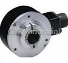
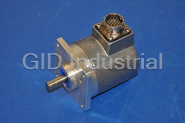
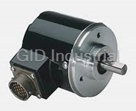


What they say about us
FANTASTIC RESOURCE
One of our top priorities is maintaining our business with precision, and we are constantly looking for affiliates that can help us achieve our goal. With the aid of GID Industrial, our obsolete product management has never been more efficient. They have been a great resource to our company, and have quickly become a go-to supplier on our list!
Bucher Emhart Glass
EXCELLENT SERVICE
With our strict fundamentals and high expectations, we were surprised when we came across GID Industrial and their competitive pricing. When we approached them with our issue, they were incredibly confident in being able to provide us with a seamless solution at the best price for us. GID Industrial quickly understood our needs and provided us with excellent service, as well as fully tested product to ensure what we received would be the right fit for our company.
Fuji
HARD TO FIND A BETTER PROVIDER
Our company provides services to aid in the manufacture of technological products, such as semiconductors and flat panel displays, and often searching for distributors of obsolete product we require can waste time and money. Finding GID Industrial proved to be a great asset to our company, with cost effective solutions and superior knowledge on all of their materials, it’d be hard to find a better provider of obsolete or hard to find products.
Applied Materials
CONSISTENTLY DELIVERS QUALITY SOLUTIONS
Over the years, the equipment used in our company becomes discontinued, but they’re still of great use to us and our customers. Once these products are no longer available through the manufacturer, finding a reliable, quick supplier is a necessity, and luckily for us, GID Industrial has provided the most trustworthy, quality solutions to our obsolete component needs.
Nidec Vamco
TERRIFIC RESOURCE
This company has been a terrific help to us (I work for Trican Well Service) in sourcing the Micron Ram Memory we needed for our Siemens computers. Great service! And great pricing! I know when the product is shipping and when it will arrive, all the way through the ordering process.
Trican Well Service
GO TO SOURCE
When I can't find an obsolete part, I first call GID and they'll come up with my parts every time. Great customer service and follow up as well. Scott emails me from time to time to touch base and see if we're having trouble finding something.....which is often with our 25 yr old equipment.
ConAgra Foods