

 Manufacturers
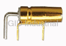
AGILENT / HP N2766A
Description
Horizonal Mini Probe Socket, qty 25
Part Number
N2766A
Price
Request Quote
Manufacturer
AGILENT / HP
Lead Time
Request Quote
Category
PROBES
Datasheet

Extracted Text
Infiniium Series Oscilloscope Probes, Accessories, and Options Selection Guide Data Sheet Table of Contents Probe Compatibility Table ................................................................2 General Purpose Probes Overview ................................................3 1007XC Family Passive Probes ..................................................4 116XA Family Passive Voltage ...................................................6 117XA Family Low Mass, Passive Voltage...............................9 High-Frequency Voltage Probes Overview ................................11 1130A/31A/32A/34A InfiniiMax High-Performance Active Probe System..................................................................12 1168A/69A InfiniiMax II High-Performance Active Probe System..................................................................15 1155A Active Single-Ended Voltage........................................18 1156A/57A/58A High-Bandwidth, Active Voltage ..............20 1163A Resistive Divider...............................................................6 54006A Resistor Divider Probe ................................................23 Differential Voltage Probes Overview.........................................24 1130A/31A/32A/34A InfiniiMax High-Performance Active Probe System..................................................................12 1168A/69A InfiniiMax II High-Performance Active Probe System..................................................................15 1153A Low-Bandwidth Active Differential Voltage ..............25 Current Probes Overview...............................................................28 1146A ac/dc Current .................................................................29 1147A High Bandwidth ac/dc Current ...................................31 High-Voltage Passive Probes Overview .....................................33 10076A (100:1)............................................................................34 N2771A (1000:1).........................................................................35 Mixed-Signal Oscilloscope Logic Probe Kit..............................36 E5396A Half-Size Soft Touch Connectorless Logic Probe.......37 Probing Accessories.......................................................................38 To ensure that you have the tools for dependable Wedge Adapters.........................................................................38 oscilloscope measurements, Agilent Technologies 0.5 mm IC Clips, PC Board Mini-Probe Sockets ....................39 EZ-Probe Positioner ...................................................................40 offers a wide range of oscilloscope probes and accessories. Each is designed for a specific Logic Analyzer/Oscilloscope Time Correlation........................41 measurement need because the physical and VoiceControl .....................................................................................42 electrical quality of the connection can make Input Devices and Storage Devices.............................................43 the difference between a good measurement E2610A Keyboard, E2609B Rackmount Kit, 1184A Testmobile.......................................................................43 and a bad one. Infiniium Advanced Analysis Options .........................................44 Probe Compatibility Table For ordering information when replac- To assist you in selecting the proper Or refer to our probe overview ing your probe or probe accessory: probe for your application: page at the beginning of each section in the table of contents Refer directly to the page number Use our probe compatibility table explaining what the different listed in the table of contents for below to find the probes that are probe types are and the models your probe model. recommended for use with your available for your Infiniium. Infiniium scope. Probe Type Probe Model 54830B/31B/32B/33A/ 54835A/45A/ 54810A/15A/ 54852A/53A/54A/55A 30D/31D/32D/33D 45B/46A/46B 20A/25A and DSO80000 Series and 8000 Series General Purpose Passive 1160A, 10:1 500 MHz Incompatible Incompatible Recommended Incompatible Page 4, 6 1161A, 10:1 500 MHz Compatible Recommended Incompatible Compatible [1] 1162A, 1:1 25 MHz Recommended Recommended Recommended Compatible [1] 1165A, 10:1 600 MHz Recommended Compatible Incompatible Incompatible 10070C, 1:1 20 MHz Recommended Compatible Compatible Compatible [1] 10073C, 10:1 500 MHz Recommended Compatible Incompatible Recommended [1] Low Mass Passive 1171A, 10:1 Recommended Recommended Incompatible Compatible [1] Page 9 Active Single-Ended 1155A, 750 MHz Recommended Compatible Recommended Compatible Page 18, 20 1156A, 1.5 GHz Recommended Recommended Recommended Compatible 1157A, 2.5 GHz Compatible Recommended Compatible Compatible 1158A, 4 GHz Compatible Recommended Compatible Compatible Resistive Divider 1163A, 10:1 Recommended Recommended Recommended Incompatible Page 6, 23 54006A, 10:1 or 20:1 Compatible [2] Recommended [2] Compatible [2] Recommended [2] Active Differential 1153A, 200 MHz Recommended Recommended Recommended Compatible Page 12, 15, 25 1130A, 1.5 GHz [6] Recommended [3] Compatible Incompatible Compatible 1131A, 3.5 GHz [6] Recommended [3] Recommended [4] Incompatible Recommended 1132A, 5 GHz [6] Compatible [3] Compatible [4] Incompatible Recommended 1134A, 7 GHz [6] Compatible [3] Compatible [4] Incompatible Recommended 1168A, 10 GHz [6] Compatible [8] Incompatible Incompatible Recommended [8] 1169A, 12 GHz [6] Compatible [8] Incompatible Incompatible Recommended [8] Current 1146A, 100 kHz Recommended Recommended Recommended Compatible [1] Page 29, 31 1147A, 50 MHz Recommended Recommended Recommended Incompatible [7] High Voltage 10076A, 4 kV Recommended Recommended Recommended Compatible [1] Page 34, 35 N2771A, 15 kV Recommended Recommended Recommended Compatible [1] Mixed-Signal Oscilloscope 54826-68701 Recommended [5] Incompatible Incompatible Incompatible Logic Probe Kit Page 36 Half-Size Soft Touch E5396A Recommended [5] Incompatible Incompatible Incompatible Connectorless Logic Probe Page 37 [1] Requires E2697A 1 MΩ input adapter. The E2697A includes one 10073C [6] Each 113XA and 1168A/9A probe amplifier supports both single-ended and general-purpose 500 MHz, 10:1 passive probe. differential measurements. [2] Requires 54855-67604 SMA-BNC adapter. [7] Order N2774A 50 MHz current probe with N2775A power supply that also requires [3] Requires 54830 Series system software revision A.03.10 or higher. For A.02.xx or the E2697A 1 MΩ input adapter. lower, order N5383A to upgrade system software. [8] Requires 54830 Series, 54850 Series, DSO80000 Series system software revision [4] Requires 54845/46 system software revision A.04.50 or higher. A.03.90 or higher. For A.02.xx or lower, order N5383A to upgrade system software. [5] Recommended for MSO8064A, MSO8104A, and 54830D/31D/32D/33D mixed signal oscilloscopes only. 2 General Purpose Probes Overview Passive voltage probes are used General purpose probes are for general purpose probing and available with attenuation ratios are made with passive compo- of 1:1, 10:1, and 20:1. The 10:1 nents only such as wires, connec- passive voltage probe is the most tors, capacitors and resistors commonly used probe, and is (when attenuation is required). supplied as a standard accessory There are no active components with all Infiniium 8000 Series such as transistors or amplifiers oscilloscopes. in the probe, and therefore pas- sive voltage probes do not need to be powered. Figure 2.3. Agilent 117XA low mass probe Figure 2.1. Agilent 1007XC general Figure 2.2. Agilent 116XA general for fine-pitched ICs, SMDs, and dense purpose passive probe. purpose passive probe. circuit boards. Model Probe Type Applications and Use Page 1007XC Family Passive voltage General purpose 4 116XA Family Passive voltage General purpose, small probe tip 6 (excluding the 1163A) 117XA Family Passive voltage Fine-pitched ICs, surface mount devices, and dense circuit boards 9 Passive Voltage Probe Advantages Limitations 1007XC are very rugged, low cost, 500 MHz maximum bandwidth easy to use, high high dynamic range Higher capacitive loading than active probes and high input resistance 116XA are economical, small in size, 600 MHz maximum bandwidth have high dynamic range and high input resistance Higher capacitive loading than active probes Less rugged compared to 1007XC 117XA feature low mass, low weight, low tip 500 MHz bandwidth capacitance compared to other passive probes 3 General Purpose Probes Overview Agilent 1007XC Family Passive Voltage • Very rugged design Standard accessories included: • Low cost • 1:1 and 10:1 • General-purpose retractable hook tip hooks onto wires and test points for hands-free probing • Ground bayonet provides short, Rugged, high-quality probes at an flexible ground lead for high- affordable price frequency measurements • General-purpose alligator clip Agilent 10070-family passive ground lead for versatile probes are a great choice if you’re grounding looking for high quality at an • Color tags (2 orange, 2 white, 2 affordable price. These general blue and 2 green) to place at purpose probes are the standard both ends of probe cable to passive probes designed for the help you quickly identify Infiniium 8000 Series oscillo- probes scopes. Ruggedized for general- purpose measurements, they fea- Optional accessories available: ture a durable cable and a solid Figure 2.4. Agilent Agilent 1007XC stainless steel probe body Family general purpose probe. 10072A encased with a hard, fracture- Fine-pitch probing kit includes 10 resistant plastic. They’re SMT clips and 2 dual-lead designed and tested to ensure the adapters probes operate in the toughest of 10075A conditions. The 1007XC family 0.5 mm IC probing kit includes probes are compatible with the four 0.5 mm IC clips and 2 dual- AutoProbe interface, which com- lead adapters pletely configures the Infiniium oscilloscopes for the probe. 5081-7705 General purpose probes are avail- Probe-tip-to-BNC (m) adapter able with attenuation ratios of 8710-2063 1:1, and 10:1 The 10:1 passive Dual-lead adapter provides easy voltage probe is the most connection from probe signal and commonly used probe, and is ground to fine-pitch probing supplied as a standard accessory accessories with all Infiniium 8000 Series oscilloscopes. Specifications Model Type of System Division Input R Input C Scope Compensation Length Number Probe Bandwidth Ratio Input R Range (scope+probe) 10070C High 20 MHz 1:1 1 MΩ 70 pF 1 MΩ n/a 1.5 m Impedance Passive 10073C High 500 MHz 10:1 2.2 MΩ 12 pF 1 MΩ 6-15 pF 1.5 m Impedance Passive 4 General Purpose Probes Overview Agilent 1007XC Family Passive Voltage Specifications Probe Parts Supplied Operating Characteristics Approximate propagation delay 7 ns Maximum input voltage 10070C: 400 V (dc + peak ac), CAT I 10073C: 500 V (dc + peak ac), CAT I One retractable hook tip Environmental Characteristics Temperature (operating) –10° C to +55° C Humidity (operating) Up to 90% relative humidity at 40° C Altitude (operating) Up to 4,600 meters (15,000 ft.) One adjustment tool Shock 50 g (400 g tip only) Ordering Information Probes and Accessories One alligator ground lead Part # Description Quantity 10070C 1:1, 1 MΩ, 1.5 m passive probe 1 10073C 10:1, 2.2 MΩ 1.5 m passive probe 1 10072A Fine-pitch probing kit with 2 dual-lead adapters 1 10075A 0.5 mm IC probing kit with 2 dual-lead adapters 1 One ground One IC tip bayonet 5081-7705 Probe-tip-to-BNC (m) adapter 1 8710-2063 Dual-lead adapter 1 Eight identification tags One probe 5 General Purpose Probes Agilent 116XA Family Passive Voltage • Economical, easy to use point that digs into solder and available for connecting to a • Compact design, removable probe avoids the danger of slipping off wide variety of test points. See handle for tight probing areas the test point and shorting to “Ordering Information” for a • Agilent 1163A, 500 Ω resistive adjacent leads. A pogo pin allows complete list. divider, 10:1 attenuation hand movement on the probes without losing contact with the Agilent 1163A Resistive Divider device under test. Agilent 1163A features low capac- The 116XA family probes are itive loading and wide bandwidth, compatible with the AutoProbe resulting in very accurate timing interface, which completely con- measurements. Resistive divider Built for Reliability figures the Infiniium oscilloscope probes are useful for probing low- for the probe. A snap-on BNC voltage signals such as ECL cir- These general purpose replace- connector simplifies attaching cuits, 50 Ω transmission lines, ment devices are built and tested the probe to the scope. Leads are and GaAs circuits. for high reliability. Kevlar strengthener has been added to the probe cable for extra pull strength. Durable probe tips are replaceable. The compact design significantly reduces the problem of probing densely populated integrated cir- cuit components or the character- istically minute conductors on printed circuit boards. These small lightweight probes allow measurements that were previ- ously quite difficult, while reduc- ing the danger of shorting. For tight probing areas, the probe Figure 2.5. Agilent 116XA family general handle can be unscrewed and purpose replacement probes. pulled back along the cable. When probing about the circuit in debug mode, the probes easily slip inside the included browsers. The browsers feature a crown Figure 2.6. No-slip browser crown point. 6 General Purpose Probes Agilent 116XA Family Passive Voltage Specifications System Model Bandwidth Division Scope Compensation Number Type of Probe (scope +probe) Ratio Input R Input C Input R Range Length 1160A High Impedance, 500 MHz 10:1 10 MΩ 9 pF 1 MΩ 6 - 9 pF 1.5 m Passive 1161A High Impedance, 500 MHz 10:1 10 MΩ 10 pF 1 MΩ 12 - 14 pF 1.5 m Passive 1162A High Impedance, 25 MHz 1:1 1 MΩ 50 pF + scope 1 MΩ n/a 1.5 m Passive capacitance 1163A 500 Ω Resistive 1.5 GHz with 10:1 500 Ω 1.5 pF 50 Ω n/a 1.5 m Divider scope model 54845A/B 1165A High Impedance, 600 MHz 10:1 10 MΩ 10 pF 1 MΩ 12 - 14 pF 1.5 m Passive typical with 54830B/31B/32B/33A 54830D/31D/32D/33D Operating Characteristics Approximate propagation delay 6.7 ns for 1160A/61A/62A/63A/65A probes 8.8 ns for 1164A probe Maximum input voltage 300 V (dc + peak ac), CAT II 10 V (dc + peak ac), CAT I for 1163A only Safety Meets IEC1010-2-31 Pulling strength (BNC to barrel) ≤ 12 lb static pull Net weight 2.6 oz Environmental Characteristics Temperature (operating) 0° C to +55° C Humidity (operating) Up to 95% relative humidity at 40° C Altitude (operating) Up to 4,600 meters (15,000 ft.) Shock 50 g (400 g tip only) 7 General Purpose Probes Agilent 116XA Family Passive Voltage Ordering Information Probes and Accessories Probe Parts Supplied Part # Description Quantity One 1160A 10:1, 10 MΩ, 1.5 m, miniature passive probe 1 browser pogo pin 1161A 10:1, 10 MΩ, 1.5 m, miniature passive probe 1 (spare) Two SMD clips 1162A 1:1, 1.5 m, miniature passive probe 1 1163A 10:1, 500 Ω, low C, 1.5 m, miniature passive probe 1 One One 1165A 10:1, 10 MΩ, 1.5 m, miniature passive probe 1 general- browser purpose 5063-2143 Probe tip to BNC (m) 1 retractable One hook tip dual-lead IC clips: See “Probing Accessories” adapter Horizontal and vertical mini-probe sockets: See “Probing Accessories” Wedge Probe Adapters: See “Probing Accessories” Two barrel insulators Replacement Parts Four spring grounds Part # Description Quantity 5063-2135 General purpose retractable hook tip 2 Two 5063-2140 Alligator ground lead 2 probe tips 5063-2120 Socketed ground lead 1 One alligator ground lead 5063-2115 Browser 1 5063-2147 Dual lead adapter 1 5063-2149 SMD clips 5 One socketed ground lead 01160-68701 Accessory kit (includes four spring grounds, 1 four browser pogo pins, four barrel insulators, one screwdriver) 5063-2136 1160A probe tip, red 5 One probe 5063-2137 1161A probe tip, brown 5 5063-2138 1162A probe tip, black 5 One screwdriver 5063-2139 1163A probe tip, grey 5 5063-2151 1164A probe tip, orange 5 Includes user’s guide and three-year warranty. 5063-2137 1165A probe tip, brown 5 8 General Purpose Probes Agilent 117XA Family Low Mass, Passive Voltage • Easy connection to fine-pitch ICs, When probing about the circuit in The 117XA probes are compatible SMDs, and dense circuit boards debug mode, the probe easily slips with the AutoProbe interface, • Light weight (< 1 gram), low inside the included browsers. The which completely configures the mass probe tip browsers feature a crown point Infiniium oscilloscope for the • 10:1 attenuation, capacitance that digs into solder and avoids probe. A snap-on BNC connector < 10 pF (1171A) the danger of slipping off the test simplifies attaching the probe to point and shorting to adjacent the scope. leads. A pogo pin allows hand movement on the probes without Suited for Today’s ICs losing contact with the device under test. An exceptionally small and light probe tip (<1 gram) and an ultra thin cable make the 117XA family ideal for connecting to and prob- ing fine-pitch ICs, surface mount devices, and dense circuit boards. The probe fits directly onto stan- dard board headers and IC clips. A range of accessories are avail- able for you to optimize interfac- ing with surface mount devices. Wedge Probe Adapters make con- venient and reliable connections to TQFP/PQFP package leads. See “Ordering Information” for a com- plete list of accessories. Figure 2.7. Agilent 117XA family probes for fine-pitch ICs, surface mount devices, and dense circuit boards. Specifications System Model Bandwidth Division Scope Compensation Number Type of Probe (scope + probe) Ratio Input R Input C Input R Range Length 1171A High Impedance, 500 MHz 10:1 10 MΩ 10 pF 1 MΩ 12 - 14 pF 1.4 m Passive 9 General Purpose Probes Agilent 117XA Family Low Mass, Passive Voltage Specifications Operating Characteristics Probe Parts Supplied Approximate propagation delay 1171A: 6.5 ns Maximum input voltage 40 V (dc + peak ac), CAT I Safety Meets IEC1010-2-31 Pulling strength (BNC to probe tip) ≤ 12 lb static pull Net weight 2.6 oz Probe tip weight < 1 gram One ground Environmental Characteristics extender Temperature (operating) 0° C to +55° C One probe One walking Humidity (operating) Up to 95% relative humidity at 40° C stick ground Altitude (operating) Up to 4,600 meters (15,000 ft.) Two pogo pins Shock 50 g (400 g tip only) Two probing pins Ordering Information One browser Probes and Accessories Part # Description Quantity 1171A 10:1, 10 MΩ, 1.4 m, low mass passive probe 1 One alligator ground lead IC clips: See “Probing Accessories” Wedge Probe Adapters: See “Probing Accessories” Replacement Parts One socketed ground lead Part # Description Quantity 5063-2122 Browser 1 One screwdriver Includes two IC clips, user’s guide, and one-year warranty. 10 High-Frequency Voltage Probes Overview Active voltage probes contain an Resistive divider probes are active component, usually a field- passive probes. They feature low effect transistor (FET), and there- capacitive loading and accurate fore need to be powered. A FET timing measurements with high- input has the advantage of pro- bandwidth signals at a much viding a very low input capaci- lower cost than active probes. tance, typically from less than 1 pF to a few pF. This low capaci- tance results in a high input impedance on frequencies up to 7 GHz. With such low loading, active probes can be used on high-impedance circuits that would be seriously loaded by passive probes. New InfiniiMax probe family. The innovative InfiniiMax probe system provides either differential- or single-ended probing solutions for the most demanding connec- tion requirements, without sacri- ficing performance. Figure 3.1. Agilent 1130A/31A/32A/34A InfiniiMax high-performance active probe. Figure 3.2. Agilent 1156A/57A/58A active probes for signals up to 4 GHz. Model Probe Type Applications and Use Page 1130A/31A/32A/34A Active Diff/SE Measure both differential and single-ended signals up to 7 GHz 12 1168A/69A Active Diff/SE Measure both differential and single-ended signals up to 13 GHz 15 1155A Active Single-Ended Measure fast transitions on low-voltage signals, 2 channels 18 1156A/57A/58A Active Single-Ended Measure fast transitions on low-voltage signals up to 4 GHz 20 1163A Resistive divider Measure fast transitions on a wide range of signal voltages 6 54006A Resistive divider Low-cost alternative for high-frequency probing 23 High-Frequency Probe Advantages Limitations Timing and voltage measurements more accurate at Active probes are more expensive than general purpose passive probes high bandwidths Resistive divider probes cost less than active probes Relatively heavy resistive loading with resistive divider probes Active probes are least intrusive to circuit under test, Active probes have lower dynamic range, lower maximum voltage and high input resistance are less rugged compared to passive probes 11 High-Frequency Active Differential/Single-Ended Probe System Agilent 1130A/31A/32A/34A InfiniiMax High-Performance Active Probe System • InfiniiMax 7 GHz, 5 GHz, 3.5 GHz, • The Agilent InfiniiMax 1130A • The groundbreaking design of and 1.5 GHz probing system series probe system supports Agilent InfiniiMax 1130A probe • Each InfiniiMax probe amplifier a wide variety of real-world system also enables users to supports both differential and applications with an exten- make either single-ended or single-ended measurements for sive line up of probe heads and differential measurements a more cost-effective solution accessories. The accessories from a single probe amplifier, • Unrivaled InfiniiMax probing can meet the most demanding depending on their choice of accessories support browsing, mechanical access requirements. probe head and accessory. This solder-in, and socket use models Small probe heads can be placed can result in significant savings at the maximum performance between densely packed PC in cost and time. The common available boards. Solder-in sockets are mode rejection of the differen- available for signals that need tial probe head reduces a mea- frequent measurement. A dif- surement’s noise floor. Overall, The Agilent InfiniiMax 1134A, ferential SMA probe head is the Agilent 1130 series probing 1132A, 1131A and 1130A probe available to connect to fixtures system delivers unmatched systems provide 7 GHz, 5 GHz, that have SMA connections. A performance, accuracy 3.5 GHz and 1.5 GHz of band- smart ergonomic design allows and connectivity. width respectively, and offer the users to set the spacing between following benefits: the probe pins (variable span). When not concerned with min- • The new probes have a flat imum probe size, designers can InfiniiMax: The World’s Best frequency response over the use a browsing sleeve to make High-Speed Oscilloscope entire bandwidth specification, holding the probe more com- Probing System eliminating the distortion and fortable. Both probe tips of the EDN Magazine has awarded loading that affect probes with differential probe can “flex” to Agilent’s InfiniiMax active probe in-band resonance. The probing support various probing angles system the 2002 Innovation of system enables engineers to and target system characteristics the Year Award. utilize their oscilloscope’s entire (z-axis compliance). Innovative bandwidth without being limited damped-wire accessories com- to measuring only 50 Ω trans- pensate for the inductance and mission lines or using passive capacitance associated with resistive divider probes that the leads, and prevent distor- produce voltage measurement tion of the measured signal. error and circuit loading. Designers can achieve system measurement bandwidths of 4.5 to 6 GHz even when manu- ally “browsing” with the probe. Solder-in probe heads and solder-in sockets provide even higher bandwidths. Figure 3.3. InfiniiMax offers you the highest performance available for measuring differential and single-ended signals. 12 High-Frequency Active Differential/Single-Ended Probe System Agilent 1130A/31A/32A/34A InfiniiMax High-Performance Active Probe System Specifications Example of characterized performance plots: differential Operating Characteristics solder-in probe head Probe bandwidth* 1134A: > 7 GHz 1132A: > 5 GHz 1131A: > 3.5 GHz 6 1130A: > 1.5 GHz 3 0 dB Rise and fall time (10% to 90%) 1134A: 60 psec -3 1132A: 86 psec -6 1131A: 100 psec -9 1130A: 233 psec -12 8 9 10 10 10 10 Frequency (Hz) System bandwidth (–3 dB) 1134A with 54855A: 6 GHz 1132A with 54854A: 4 GHz Figure 3.4. Swept frequency response. 1131A with 54853A: 2.5 GHz 1131A with 54852A: 2 GHz 1130A with MSO/DSO8104A, 54832B/D, 33A/D: 1 GHz 0 Input capacitance** Cm = 0.1 pF Cm is between tips. -10 Cg = 0.34 pF Cg is to ground for each tip. -20 Cdiff = 0.27pF Differential mode capacitance = Cm + Cg/2 dB -30 Cse = 0.44 pF Singe-ended mode capacitance = Cm + Cg -40 -50 Input resistance* Differential mode resistance = 50 kΩ±1% -60 8 9 10 Single-ended mode resistance = 25 kΩ±1% 10 10 10 Frequency (Hz) Input dynamic range ±2.5 V Figure 3.5. Common mode rejection Input common mode range ±6.75 V dc to 100 Hz; ±1.25 V >100 Hz vs. frequency. Maximum signal slew rate 18 V/ns when probing a single-ended signal 30 V/ns when probing a differential signal DC attenuation 10:1 ± 3% before calibration on oscilloscope 10:1 ± 1% after calibration on oscilloscope Zero offset error referred < 30 mV before calibration on oscilloscope to input < 5 mV after calibration on oscilloscope Offset range* ± 12.0 V when probing single-ended Offset accuracy < 3 % setting before calibration on oscilloscope < 1 % setting after calibration on oscilloscope Noise referred to input 3.0 mVrms Propagation delay ~6 nsec (This delay can be deskewed relative to other signals.) Maximum input voltage* 30 Vpeak, CAT I ESD tolerance > 8 kV from 100 pF, 300 Ω HBM * Denotes warranted specifications, all others are typical. ** Measured using the probe amplifier and solder-in differential probe head with full bandwidth resistors. 13 High-Frequency Active Differential/Single-Ended Probe System Agilent 1130A/31A/32A/34A InfiniiMax High-Performance Active Probe System Ordering Information Probe Amplifier Model Part # Description Quantity 1134A 7 GHz InfiniiMax Probe Amplifier (order one or more probe heads or connectivity kits per amplifier). 1 1132A 5 GHz InfiniiMax Probe Amplifier (order one or more probe heads or connectivity kits per amplifier). 1 1131A 3.5 GHz InfiniiMax Probe Amplifier (order one or more probe heads or connectivity kits per amplifier). 1 1130A* 1.5 GHz InfiniiMax Probe Amplifier (order one or more probe heads or connectivity kits per amplifier). 1 * Note: Requires 54830 Series system software revision A.03.10 or higher. For A.02.xx or lower, order N5383A to upgrade system software. Connectivity Kits Model Part # Description Quantity E2669A InfiniiMax connectivity kit for differential/single-ended measurements. Includes one 1 differential browser, four solder-in differential probe heads and two socketed differential probe heads. Includes all necessary accessories. E2668A InfiniiMax connectivity kit for single-ended measurements. Includes one single-ended browser, 1 one solder-in probe heads and one socketed probe heads. Includes all necessary accessories. Individual Probe Heads Part # Description Quantity E2675A InfiniiMax differential browser probe head and accessories. Includes 20 replaceable tips and 1 ergonomic handle. Order E2658A for replacement accessories. E2676A InfiniiMax single-ended browser probe head and accessories. Includes 2 ground collar 1 assemblies, 10 replaceable tips, a ground lead socket and ergonomic handle. Order E2663A for replacement accessories. E2677A InfiniiMax differential solder-in probe head and accessories. Includes 20 full bandwidth and 1 10 medium bandwidth damping resistors. Order E2670A for replacement accessories. E2678A InfiniiMax single-ended/differential socketed probe head and accessories. Includes 48 full 1 bandwidth damping resistors, 6 damped wire accessories, 4 square pin sockets and socket heatshrink. Order E2671A for replacement accessories. E2679A InfiniiMax single-ended solder-in probe head and accessories. Includes 16 full bandwidth and 1 8 medium bandwidth damping resistors and 24 zero ohm ground resistors. Order E2672A for replacement accessories. E2695A Differential SMA probe head. Includes semi-rigid coax to change span between SMA connectors. 1 Adapters Part # Description Quantity N1022A Adapts 113X/115X active probes to 86100 Infiniium DCA. 1 14 High-Frequency Active Differential/Single-Ended Probe System Agilent 1168A/69A InfiniiMax II High-Performance Active Probe System InfiniiMax II: The World’s Best High-Speed InfiniiMax II probe heads Probing System Just Got Better InfiniiMax offers you the highest performance available for measuring differential and single-ended signals, with flexible connectivity solutions for today’s high-density ICs and circuit boards. InfiniiMax probes have fully characterized performance for all of their various probe heads. This includes: 12 GHz Hi-BW solder-in differential probe • Swept frequency response plot head provides maximum bandwidth and • Common mode rejection vs. frequency plot minimizes capacitive loading to ≤ 210 fF. • Impedance vs. frequency plot Variable spacing from 0.2 to 3.3 mm (8 to • Time-domain probe loading plot 130 mills). • Time-domain probe tracking plot One-year standard warranty on active probes and a variety of Agilent support options to choose from. Controlled impedance transmission lines in every probe head deliver full performance versus the performance limitations produced by traditional wire accessories. 12 GHz Hi-BW differential browser provides Probe interface software allows you to save the maximum bandwidth for hand-held or probe calibration information for up to 10 different probe holder use. Variable spacing from 0.2 to heads per channel and will automatically retrieve 3.3 mm (8 to 130 mills). calibration data for a probe amplifier as it is attached to the scope. 12 GHz Hi-BW High-input impedance active probes minimize differential loading, support differential measurements and DC SMA probe offset, and can compensate for cable loss. head provides maximum Probe calibration software delivers the most bandwidth for accurate probe measurements, linear phase SMA fixtured response and allows various probe combinations differential to be deskewed to the same reference time. pairs. Two new high-bandwidth InfiniiMax II Series probe amplifiers have been added to the InfiniiMax product line. InfiniiMax I probe amplifiers and probe heads can also be used with InfiniiMax II Series probe amplifiers for lower performance applications. 15 High-Frequency Active Differential/Single-Ended Probe System Agilent 1168A/69A InfiniiMax II High-Performance Active Probe System Specifications Operating Characteristics Bandwidth* 1169A: > 12 GHz (13 GHz typical) 1168A: > 10 GHz Rise and fall time Probe only, 1169A: Probe only, 1168A: • Probe only 28 ps (20 - 80%), 40 ps (10 - 90%) 34 ps (20 - 80%), 48 ps (10 - 90%) • When phase compensated by 1169A with DSO81204A: 1168A with DSO81004A: 80000 Series oscilloscope 25 ps (20 - 80%), 36 ps (10 - 90%) 30 ps (20 - 80%), 42 ps (10 - 90%) 1169A with DSO81304A: 23 ps (20 - 80%), 33 ps (10 - 90%) System bandwidth (–3 dB) 1169A with DSO81304A: 13 GHz (typical) 1168A with DSO81004A: 10 GHz 1169A with DSO81204A: 12 GHz 1 Input capacitance Cm = 0.09 pF Cm is between tips Cg = 0.26 pF Cg is to ground for each tip Cdiff = 0.21 pF Differential mode capacitance = Cm + Cg/2 Cse = 0.35 pF Single-ended mode capacitance = Cm + Cg Input resistance* Differential mode resistance = 50 kΩ±2% Single-ended mode resistance = 25 kΩ±2% Input dynamic range 3.3 V peak to peak Input common mode range 6.75 V peak to peak dc to 100 Hz; 1.25 V peak to peak > 100 Hz Maximum signal slew rate 25 V/ns when probing a single-ended signal 40 V/ns when probing a differential signal DC attenuation 3.45:1 Zero offset error referred to input ± 1.5 mV Offset range ± 16.0 V when probing single-ended Offset accuracy < 3% of setting Noise referred to input 2.5 mV rms, probe only Propagation delay ~6 ns (this delay can be deskewed relative to other signals) Maximum input voltage 30 V peak, CAT I ESD tolerance > 8 kV from 100 pF, 300 Ω HBM * Denotes warranted specifications, all others are typical. 1 Measured using the probe amplifier and N5381A solder-in differential probe head. 16 High-Frequency Active Differential/Single-Ended Probe System Agilent 1168A/69A InfiniiMax II High-Performance Active Probe System Ordering Information InfiniiMax II Probe Amplifiers Description 1169A 12 GHz InfiniiMax probe amp – order one or more probe heads. 1168A 10 GHz InfiniiMax probe amp – order one or more probe heads. InfiniiMax II Probe Heads Recommended for use with InfiniiMax II probe amplifiers N5380A InfiniiMax II 12 GHz differential SMA adapter. Includes semi-rigid coax to change span between SMA connectors. N5381A InfiniiMax II 12 GHz differential solder-in probe head and accessories. Includes wire for replacement leads. Order 01169-21306 for 0.005 inch or 01169-81301 for 0.007 inch replacement nickel wire. N5382A InfiniiMax II 12 GHz differential browser. Includes wire for replacement leads. Order 01169-21304 for 0.005 inch replacement steel wire. InfiniiMax I probe heads* Can be used with InfiniiMax II probe amplifiers with limitations E2675A InfiniiMax differential browser probe head and accessories. Includes 20 replaceable tips and ergonomic handle. Order E2658A for replacement accessories. E2676A InfiniiMax single-ended browser probe head and accessories. Includes 2 ground collar assemblies, 10 replaceable tips, a ground lead socket and ergonomic browser handle. Order E2663A for replacement accessories. E2677A InfiniiMax differential solder-in probe head and accessories. Includes 20 full bandwidth and 10 medium bandwidth damping resistors. Order E2670A for replacement accessories. E2678A InfiniiMax single-ended/differential socketed probe head and accessories. Includes 48 full bandwidth damping resistors, 6 damped wire accessories, 4 square pin sockets and socket heatshrink. Order E2671A for replacement accessories. E2679A InfiniiMax single-ended solder-in probe head and accessories. Includes 16 full bandwidth and 8 medium bandwidth damping resistors and 24 zero ohm ground resistors. Order E2672A for replacement accessories. E2695A Differential SMA probe head. Includes semi-rigid coax to change span between SMA connectors. * (See Benefits section of publication number 5989-1487EN/ENUS for specifications and limitations when used with InfiniiMax II Series probe amplifiers.) Adapters Description N1022A Adapts 113x/115x active probes to 86100 Infiniium DCA. 17 High-Frequency Active Single-Ended Voltage Probes Agilent 1155A Active Single-Ended Voltage • Easy connection to fine-pitch ICs, SMDs, and dense circuit boards • Lightweight (< 1 gram), low mass probe tip • Two channels, 750 MHz bandwidth Low Cost, Great Performance Talk about big performance in a small package! The two-channel, low-mass 1155A combines a probe tip that weighs less than 1 gram with the superior per- Figure 3.6. Agilent Wedge Probe Adapter for reliable, hands-free probing of 0.5 mm ICs. formance of an active probe. It’s a powerful combination, ideal for connecting to and testing fine- pitch ICs, surface mount devices, and dense circuit boards. 1M The 1155A probe joins high 100k 1155A bandwidth (750 MHz), low input 10k capacitance (2 pF), and high 1160A resistance (1 MΩ). These features 1k are well suited for measuring fast 100 transition times on low voltage 10k 100k 1M 10M 100M 1G signals that cannot tolerate the Frequency (Hz) circuit loading of passive probes. Figure 3.7. Comparison of input impedance A Wedge Probe Adapter, included versus frequency, showing the higher with the probe, allows for hands- input impedance of the 1155A probe. free probing of 0.5 mm ICs. The Wedge provides accurate, me- chanically non-invasive electrical contact to the IC legs with little chance of shorting. It’s easy to insert and it stays put. For more information on the Wedge, see “Probing Accessories.” Leads are available for connecting to a wide variety of test points. See “Ordering Information” for a complete list. These probes are compatible with the AutoProbe interface, which completely configures the oscillo- scope for use with the probe. Power for the active probe is sup- plied by the oscilloscope. A snap- Figure 3.8. Agilent 1155A for fine-pitch ICs, SMDs, and dense on BNC connector simplifies circuit boards. attaching the probe to the scope. 18 Input Impedance (Ω) High-Frequency Active Single-Ended Voltage Probes Agilent 1155A Active Single-Ended Voltage Specifications Operating Characteristics Accessories Supplied Bandwidth (–3 dB) dc to ≥ 750 MHz Four probing pins System bandwidth 500 MHz with 600 MHz MSO/DSO8064A, 54830B/D, 31B/D scopes 670 MHz with 1 GHz MSO/DSO8104A, 54832B/D, 33B/D scopes Five SMT clips Rise time* ≤ 470 ps Attenuation factor* 10:1 ± 3% dc input resistance* 1 MΩ±2% Two flexible leads Input capacitance 2 pF (typical) Flatness Less than ±10% for first 6 ns, ±4% from 6 ns to 20 µs, ±1.5% thereafter Input dynamic range 0 to 6.0 V Two spacing ground adapters Maximum input voltage ±40 V (dc + peak ac), CAT I Environmental Characteristics Two red, two black SMT leads Temperature (operating) 0° C to +55° C Humidity (operating) Up to 95% relative humidity at 40° C * Denotes specified parameters. All others are characteristics. One BNC-to-probe tip adapter (E9638A) Ordering Information Probe and Accessories Two 0.5 mm Wedge Part # Description Quantity Probe Adapters 1155A Low mass, 2-channel active probe 1 Includes user’s guide and one-year warranty. IC clips: See “Probing Accessories” Wedge Probe Adapters: See “Probing Accessories” Replacement Parts Part # Description Quantity 01145-61602 Probe tip and cable 1 16517-82104 SMT leads 4 red, 4 black 16517-82105 Spacing ground adapter 20 16517-82106 Flexible leads 20 16517-82107 Pin probe kit 4 5090-4833 SMT clip 20 19 High-Frequency Active Single-Ended Voltage Probes Agilent 1156A/57A/58A High-Bandwidth, Active Single-Ended Voltage • Ideal for a range of hi-speed applications • 88 ps rise time (on 4 GHz model) • 100 kΩ, 0.8 pF, non-resonant input impedance • 5 V peak-to-peak dynamic range • ± 15 V offset • Accessories designed for minimal device loading and optimal response • Small size for easier probing As the speeds in your design increase, you may notice more overshoot, ringing, and other per- Figure 3.9. Agilent 1156A/57A/58A active probe for hi-speed signals. turbations when connecting an oscilloscope probe. Probes form a resonant circuit where they con- nect to the device. If this reso- nance is within the bandwidth of onscreen matches the waveform Agilent offers a variety of acces- the oscilloscope probe you are at the probe tip. The 1158A offers sories optimized to give you the using, it will be difficult to deter- a flat response for the entire most accurate reproduction of mine if the measured perturba- bandwidth of a 4 GHz probe! your signal. In addition, the per- tions are due to your circuit or formance of each accessory is the probe. Small Size characterized for you. Now you can make informed decisions and These probes are compatible with Have you experienced problems get the best measurement for the AutoProbe interface, which with large, clunky probes? If so, your environment. Superior per- completely configures the oscillo- you probably found your probe formance combined with the scope for use with the probe. awkward to hold and had diffi- knowledge to use it–that’s how Power for the active probe is sup- culty connecting to your signals. Agilent helps you do your job better. plied by the oscilloscope. With the small size of the 1156A/57A/58A, you can handle Faithful Reproduction of Your Signal the probe expertly and gain access to tight spaces. Plus, the Now you can accurately measure low mass makes the probe more your hi-speed signals without durable. Agilent makes your job introducing errors from a probe easier–giving you performance that has a resonant input imped- that is easy to use. ance or non-flat frequency response. With the 1156A/57A/58A Superior Accessories probes, a damping resistor is placed as close as possible to the Your device under test (DUT) point being probed, which keeps determines the type of probing the input impedance from res- accessories you need. Of course, onating low, and it also allows a there are electrical trade-offs flat frequency response across depending on the type of connec- the entire bandwidth of the probe. tion you use. Longer connections Figure 3.10. Probe with resistive signal pin Finally, there is a high-bandwidth from your DUT produce lower and ground blade. active probe where the waveform performance probing systems. 20 High-Frequency Active Single-Ended Voltage Probes Agilent 1156A/57A/58A High-Bandwidth, Active Single-Ended Voltage Specifications Operating Characteristics Bandwidth (–3 dB) 1156A: > 1.5 GHz; 1157A: > 2.5 GHz; 1158A: > 4 GHz System bandwidth (–3 dB) 1156A with MSO/DSO8104A, 54832B/D, 54833A/D scope: 1 GHz; 1157A with 54852A scope: 2 GHz; 1157A with 54853A scope: 2.5 GHz; 1158A with 54854A scope: 4 GHz Rise and fall time (10% to 90%) 1156A: < 233 ps; 1157A: < 140 ps; 1158A: < 88 ps calculated from t = 0.35/bandwidth Figure 3.11. Notice how closely output r matches input. Graph shows V and V in out Input capacitance 0.8 pF when driven from a 25Ω source. Input resistance [1] 100 kΩ 1% Flatness, swept response 0.2 dB: 100 kHz to 100 MHz; 0.4 dB: 100 MHz to 2.5 GHz; 2.0 dB: 2.5 GHz to 4.0 GHz Flatness, step response 15% overshoot: 35 ps input edge; 10% overshoot: 75 ps input edge; 2%: 1 ns after edge Dynamic range [2] > 5.0 V peak-to-peak dc attenuation [1] 10:1 ± 3% before calibration [4]; 10:1 ± 1% after calibration [4] Zero offset error < 30 mV before calibration [4]; referred to input [1] < 5 mV after calibration [4] Figure 3.12. The flat response means the Offset range [1] ±15.0 V waveform on the scope screen will match the waveform at the probe tip—across Offset accuracy [1] < 3% of setting before calibration [4]; an entire 4 GHz bandwidth. Graph shows 1% of setting after calibration [4] response (V /V ). out in Noise referred to input 3.0 mVrms Propagation delay 5.5 ns Maximum input voltage 40 V peak, CAT I [3] ESD tolerance > 5 kV from 100 pF, 300 Ω HBM Temperature drift Offset: < 1.0 mV/°C; Attenuation (Gain): 0.1 %/°C [1] Denotes warranted specifications, all others are typical. [2] For waveforms with edges > 3 ns, the dynamic range is > 12.0 V peak-to-peak. [3] Installation category (over voltage category) I: Signal level, special equipment, or parts of equipment, telecommuni- cation, electronic, etc., with smaller transient overvoltage than installation category (overvoltage category) II. [4] Probe calibrated to scope channel (under Probes Setup menu). Environmental Characteristics Temperature Operating: 0° C to +55° C; Non-operating: –40° C to +70° C Humidity Operating: Up to 95% relative humidity (non-condensing) at +40° C; Non-operating: Up to 90% relative humidity at +65° C 21 High-Frequency Active Single-Ended Voltage Probes Agilent 1156A/57A/58A High-Bandwidth, Active Single-Ended Voltage Ordering Information Part # Description Quantity Accessories Supplied 1156A 1.5 GHz active probe* 1 1157A 2.5 GHz active probe* 1 Twelve 130 Ω resistive signal 1158A 4 GHz active probe* 1 pins (orange)* Two solderable-tip 5 cm resistive * The Infiniium 54800A Series scope requires version A.04.30 or greater of the application software to work with the signal leads* 1156A/7A/8A probes. An LS-120 drive is required for this upgrade. Accessories Two socket-end 5 cm resistive signal Part # Description Quantity leads* E2637A Precision measurement kit (includes 2 solderable 1 ground sockets with 2 green resistive signal pins) Two socket-end 10 cm resistive E2638A Solderable-tip 5 cm resistive signal leads (10) 1 signal leads* with ground leads (3) E2639A Micro clips 4 E2640A Resistive signal pins, (orange) 8 Twelve ground blade assemblies* E2641A Ground blade assembly 8 Twelve solderable SMT ground pins* Twelve solderable through-hole ground pins* Four micro clips Twelve offset ground pins Two solderable-tip 5 cm ground Two socket-end leads 5 cm ground leads Two socket-end 5 cm 90° pin ground leads Includes user’s guide and one-year warranty. These accessories are properly damped to give you a flat transmitted response and non-resonant input impedance. Use these supplied accessories to get the best performance from your probe. 22 High-Frequency Passive Voltage Probe Agilent 54006A 6 GHz Resistor Divider Probe • Useful in probing high-frequency you to see signals at specific signals with low source impedance points, such as the input to a • Supplied with 10:1, 500 Ω and gate. Agilent 54006A’s input 20:1, 1 kΩ resistor dividers capacitive loading is approxi- • Low capacitive loading to mately 0.25 pF, allowing you to extremely high frequencies get very accurate timing measure- ments for a wide bandwidths of signals. The Agilent 54006A allows you to The 54006A probe is a good, probe signals up to 6 GHz using low-cost alternative for high replaceable tips that provide frequency probing where the either 10:1 division ratio with higher resistive loading is not an 500Ω input resistance, or a Figure 3.14. Agilent 54006A for probing issue and the other features of 20:1 division ratio with 1 kΩ high frequency, up to 100 Ω impedance the InfiniiMax probing system signals. input resistance. This 6 GHz are not needed (such as differen- probe gives access to circuit tial inputs and multiple connec- nodes that are not 50Ω or do not tivity options). have 50Ω connectors allowing Specifications Operating Characteristics Bandwidth (–3 dB) 6 GHz Attenuation ratio 10:1, 20:1 Input resistance 500 Ω, 1 kΩ Input capacitance 0.25 pF Max dc volts 20 V Length in meters (feet) 0.9 m (3 ft) Ordering Information Part # Description Quantity 54006A* 6 GHz Resistor Divider Probe 1 Includes: One 10:1 500 Ω probe body, six 450 Ω resistors, One 20:1, 1 kΩ probe body, six 950 Ω resistors, One 36 in, 50 Ω coaxial cable, SMA (m-m) One blocking cap, 10 GHz-26 GHz APC – 3,5 (m-f) * Requires the 54855-67604 SMA to precision-BNC adapter to connect to BNC scope input. 23 Differential Voltage Probes Overview Differential probes are active to the two inputs, removing the Differential probes are used with probes with two inputs, one posi- dc or common mode signals and RF communication ICs, semicon- tive and one negative, as well as a leaving the signal of interest. The ductor characterization (RAM- separate ground lead. They are common mode rejection ratio BUS, Double Data Rate, DRAM, used to look at signals that are (CMRR) characterizes how effec- AGP), battery-powered communi- referenced to each other instead tively the probe rejects signals cation and computing equipment of earth ground and to look at common to each input. The CMRR (cellular phone, laptop computer, small signals in the presence of for differential signals is much etc.), disk drive read-write chan- large dc offsets or other common higher than using two passive nel signals, power supply design mode signals such as noise. The probes and subtracting the sig- and verification, motor speed differential amplifier in the probe nals with a math function. controls, electronic high-power rejects signals that are common converters, and other applica- tions where signals are “floating” above ground. Figure 4.1. Agilent 1153A for probing low-bandwidth differential signals. Figure 4.2. Agilent 1130A InfiniiMax probe amplifier and E2675 differential browser probe head, ordered separately. Model Probe Type Applications and Use Page 1153A Active Differential Measure low-bandwidth differential signals 25 1130A/31A/32A/34A Active Diff/SE Measure both differential and single-ended signals up to 7 GHz 12 1168A/69A Active Diff/SE Measure both differential and single-ended signals up to 13 GHz 15 Differential Probe Advantages Limitations View small signals in the presence of dc or More expensive than general-purpose probes other common mode signals Less dynamic range than using two passive probes 1153A probes both low- and high-voltage 200 MHz bandwidth differential signals with low thermal drift 1168A/69A and 1130A/31A/32A/34A probes both Lower dynamic range and lower maximum input voltage single-ended and differential signals up to 13 GHz bandwidth 24 Active Differential Voltage Probes Agilent 1153A Low-Bandwidth Active Differential Voltage • View of low-bandwidth differential the input dc voltage level pre- ity to damage from electrostatic signals in the presence of much vents the use of LF reject. LF discharge and other accidental larger common-mode signals reject, like ac coupling, blocks exposure to excessive voltage. • dc to 200 MHz bandwidth the dc component in a signal Special attention is paid to isolat- • Input from ±300 mV (dc + peak ac) without degrading low frequency ing critical parts from shock. to ±30 V with attenuation CMRR, which occurs when you • 3000:1 CMRR at 1 MHz use blocking capacitors to accom- The probe is compatible with the • Input coupling: dc offset, low- plish ac coupling. The probe’s AutoProbe interface, which com- frequency reject, ac coupling dual-path amplifier design pro- pletely configures the Infiniium • Low dc thermal drift vides superior dc stability by scope for the probe. The probe reducing the drift to less than interface recognizes the probe 50 µV dc per degree Celsius. and automatically sets up the proper power, coupling modes, Reliable Probing of The 1153A is designed for relia- 50Ω impedance, and offset Low-Bandwidth Signals bility through use of over-voltage range. A snap-on BNC connector protection circuitry, which simplifies connecting the probe The Agilent 1153A is a 1:1 FET decreases the probe’s susceptibil- to the scope. differential probe with 200 MHz bandwidth and 3000:1 CMRR (Common Mode Rejection Ratio) at 1 MHz. Two attenuators, 10:1 and 100:1, expand the dynamic range of the inputs up to + 30 V. The probe has a high input resist- ance of 1 MΩ and low input capacitance of 7 pF to minimize circuit loading. Input coupling modes include dc, dc with variable offset, and low- frequency (LF) reject. The probe also comes with an ac coupling adapter for those cases where Figure 4.3. Agilent 1153A 1:1 FET differential probe with 200 MHz bandwidth. 25 Active Differential Voltage Probes Agilent 1153A Low-Bandwidth Active Differential Voltage Specifications Operating Characteristics Bandwidth (–3 dB) dc to 200 MHz [1] Rise time 1.75 ns calculated from t = (0.35/bandwidth) r dc gain accuracy* 2% (with 50 ± 0.1 Ω load) dc attenuator accuracy 2% Linear differential input range ±0.3 V (1:1); ±3.0 V (10:1); ±30 V (100:1) dc offset ±18 V (1:1); ±180 V (10:1); ±500 V (100:1) Common mode operating range dc: ±18 V (1:1); ±180 V (10:1); ±500 V (100:1) dc to 30 Hz: linearly decreased to 30 Hz value 30 Hz to 200 MHz: ±0.5 V (1:1); ±5 V (10:1); ±50 V (100:1) (voltages are peak voltage) Maximum allowable input voltage* 200 V (dc + peak ac) CAT I, 1:1; 500 V (dc + peak ac) CAT I, with attenuators common or differential modes Input coupling dc, LF reject, and ac. ac coupling is provided via an adapter that attaches to the probe. LF reject response (–3 dB) is selectable independent of attenuators at 1.7 Hz (LFR1) and 0.14 Hz (LFR2). CMRR* See graph on next page. ac coupling 15 Hz (1:1); 1.5 Hz (10:1). Low-Frequency Response (–3 dB) with ac coupling adapter and input 1.5 Hz (100:1) coupling set to dc. dc thermal drift ≤ 50 µV dc/°C Input RC 1:1 R: 1 MΩ C: 7 pF 10:1 R: 9 MΩ C: 3.5 pF 100:1 R: 10 MΩ C: 2.0 pF Output termination impedance 50 Ω Safety Meets IEC 1010-2-31 Environmental Characteristics Temperature Operating: 0° C to +55° C; Non-operating: –40° C to +70° C Humidity Operating: 95% relative humidity at 40° C; Non-operating: 90% relative humidity at +65° C Altitude Operating: Up to 4,600 m (15,000 ft); Non-operating: Up to 15,300 m (50,000 ft) * Denotes specified parameters. All others are characteristics. [1] For maximum signal fidelity, above 100 MHz, limit probe output into 50Ω to ≤ 300 mV peak-to-peak. 26 Active Differential Voltage Probes Agilent 1153A Low-Bandwidth Active Differential Voltage 10000:1 5000:1 DC/Lf Reject Typical: 2000:1 DC/Lf Reject Minimum: 1000:1 10:1 attenuator 100:1 attenuator 100:1 10:1 3:1 AC Coupler 1:1 10 Hz 100 Hz 1 kHz 10 kHz 100 kHz 1 MHz 10 MHz 100 MHz Figure 4.4. dc component in a signal blocked using low-frequency reject without degrading low-frequency CMRR. Ordering Information Probe and Accessories Part # Description Quantity 1153A 200 MHz differential probe 1 5959-9335 Long (5.5 inch) test lead 5 IC clips: See “Probing Accessories” Probe Parts Supplied One 10:1 One 100:1 One ac attenuator attenuator coupling adapter adapter adapter One two-inch extension lead package (5) One differential probe One One shielded five-inch signal ground lead lead Twenty Includes one test board, flat-blade alignment mini clips tool, strip of 20 circuit connection posts, user’s guide, and one-year warranty 27 Current Probes Overview Current probes sense the current flowing through a conductor and convert it to a voltage that can be viewed and measured on an oscil- loscope. There are two types of current probes for oscilloscopes, ac current probes (usually pas- sive probes) and ac/dc current probes (usually active probes). Both types use the same principle of transformer action for sensing ac current in a conductor. The alternating current flowing through a conductor causes a flux field to build and collapse accord- ing to the amplitude and direc- tion of current flow. The ac cur- rent probe head is actually a coil— when placed in this field the changing flux field induces a volt- age across the coil. The ac/dc cur- Figure 5.1. Agilent 1146A low-cost rent probes also contain a Hall ac/dc current probe. Effect device to sense dc and low frequency ac. Because dc doesn’t cause a changing flux field it can- not be sensed by transformer action. Also, at frequencies very close to dc, the flux field may not change fast enough for measura- ble transformer action. Figure 5.2. Agilent 1147A general- purpose ac/dc current probe. Model Probe Type Applications and Use Page 1146A ac/dc Current Measure dc and ac current simultaneously. Useful for 29 lines type power measurements. 1147A ac/dc Current Measure dc and ac current simultaneously. Useful for 31 pwm/switching power measurements. Current Probe Advantages Limitations 1146A low-cost model measures ac and dc current 100 kHz bandwidth to 100 Arms without breaking into the circuit 1147A measures ac and dc current to 50 MHz 15 A rated current without breaking into the circuit 28 Current Probes Agilent 1146A ac/dc Current • Low-cost solution ure the dc and ac output signals • ac/dc currents measured proportional to the total current. simultaneously A battery level indicator and • Accurate measurements overload indicator help insure of currents: 100 mA to proper readings. 100 Arms, dc to 100 kHz • Load impedance > 1 MΩ/100 pF A narrow, elongated clamping mechanism lets you easily probe in crowded cable bundles and cir- cuit boards. The probe connects Within Budget, Without Compromise directly to an oscilloscope through a 2 meter coaxial cable The low-cost 1146A probe with an insulated BNC. expands oscilloscope applications in industrial, automotive and Probe power is provided by the power environments and is ideal battery, so there is no need for an for analysis and measurement of external amplifier or power supply. distorted current waveforms and harmonics. Accurate display and measurement of currents from 100 mA to 100 Arms, dc to 100 kHz, are made by using Hall Effect technology, eliminating the need for an electrical connection to the circuit. Low phase shift makes this probe ideal for power quality measure- ments, while the high sensitivity makes it a great tool for measur- ing low-voltage signals. For true Figure 5.3. Agilent 1146A 100 mA to 100 Arms, dc to 100 kHz probe. root mean square (RMS) measure- ments, the 1146A lets you meas- 29 Current Probes Agilent 1146A ac/dc Current Specifications Operating Characteristics Current range* 100 mV/A: 100 mA to 10 A peak; 10 mV/A: 1 to 100 A peak Output signal 1000 mV peak max ac current accuracy* Range Accuracy (after calibration and for one year) 100 mVA (50 mA to 10 A peak) 3% of reading ± 50 mA (zero probe before making 10 mVA (500 mA to 40 A peak) 4% of reading ± 50 mA measurement) 10 mVA (40 A to 100 A peak) 15% max at 100 A Phase shift [1] < 1° from dc to 65 Hz on 10 mV/A < 1.5° from dc to 65 Hz on 100 mV/A Frequency range* dc to 100 kHz (–3 dB with current derating) Noise Range 10 mV/A: 480 µV; Range 100 mV/A: 3 mV Slew rate Range 10 mV/A: 20 mV/µs; Range 100 mV/A: 0.3 V/µs Load impedance > 1 MΩ/100 pF Insertion impedance (50/60 Hz) 0.01 Ω Rise or fall time Range 100 mV/A: 3 µs; Range 10 mV/A: 4 µs Working voltage 600 Vrms maximum Common mode voltage 600 Vrms maximum Influence of adjacent conductor < 0.2 mA/A ac Influence of conductor position 0.5% of reading at 1 kHz in jaw Battery 9 V alkaline (NEDA 1604A, IEC 6LR61) Low battery Green LED when ≥ 6.5 V Overload indication Red LED indicates input greater than selected range Typical consumption 8.6 mA Battery life 55 hours typical * Characteristics marked with asterisks are specified performance. Others are typical characteristics. [1] Reference conditions 23° C ± 5° C, 20 to 75% relative humidity, dc to 1 kHz, probe zeroed, one minute warmup, batteries at 9 V + 0.1 V, external magnetic field < 40 A/m, no dc component, no external current carrying conductor, 1 MΩ/100 pF load, conductor centered in jaw. Ordering Information Part # Description Quantity 1146A ac/dc oscilloscope current probe 1 30 Current Probes Agilent 1147A High Bandwidth ac/dc Current • General purpose, high-frequency A Degauss function allows the The 1147A is compatible with the current probing removal of any residual magnet- AutoProbe interface, which com- • ac, dc currents measured ism that has built up in the mag- pletely configures the oscillo- simultaneously netic core due to power on/off scope for the probe. Probe power • dc to 50 MHz bandwidth switching or excessive input. In is provided by the scope, so there • 15 A continuous, 50 A peak dc addition, voltage offset or temper- is no need for an external amplifi- and ac pulse current ature drift on the probe can be er or power supply. A snap-on easily corrected by using the zero BNC connector simplifies con- adjustment dial. necting the probe to the scope. Accurate Current Measurements Without Breaking the Circuit The 1147A is a wide bandwidth, dc to 50 MHz, current probe. The probe offers flat frequency response across the entire dc to 50 MHz bandwidth, low noise (< 2.5 mArms) and low-circuit insertion loss, making it ideal for general-purpose, high-frequency current probing in lab and bench environments. This probe is the best choice for measuring steady state or transient current of motor drives, switching power Figure 5.4. Agilent 1147A 15 A rated current, supplies, inverters, controllers, 50 A peak current. disk drives, LCD displays, and current amplifiers driving induc- tive loads. -10 The probe’s hybrid technology includes a Hall Effect device to -20 sense the dc current and a cur- rent transformer to sense the ac -30 current, making an electrical con- nection to the circuit unneces- -40 sary. Using split core construc- tion, the probe easily clips on and -50 off of a conductor up to 5 mm in -60 diameter. 1 100 10k 1M 100M Frequency (Hz) Figure 5.5. Frequency response chart showing the accuracy of the 1147A for probing wide bandwidth currents. 31 Amplitude (0db =IV) Current Probes Agilent 1147A High Bandwidth ac/dc Current Operating Characteristics Bandwidth (–3 dB) dc to 50 MHz 1 Rise time 7 ns Accuracy* ±1% of reading ±1 mV Maximum continuous current 15 A (acrms + dc) Refer to derating curves above 5 kHz. Maximum peak current 50 A for pulse width ≤10 µs Probe sensitivity 0.1 V/A Noise ≤2.5 mArms with 20 MHz bandwidth limiting Effect of external magnetic fields Equivalent to ≤20 mA (for a 400 A/m magnetic field dc to 60 Hz) Temperature coefficient ±2% or less (0° C to 40° C) Maximum measurable 5 mm (0.2 inch) cable diameter Sensor cable length 1.5 m (59 inch) 1 Rise time is calculated as 0.35/bandwidth. * Denotes warranted specification for the N2774A probe. All others are typical. Valid for 23º C ± 3º C (73º F ± 5º F), at least 30 minutes after power on. Requires 1 MΩ termination. Ordering Information Part # Description Quantity 1147A 50 MHz current probe 1 N2774A 50 MHz current probe. Same as 1147A, only 1 with standard BNC scope connection. Use with 54852A/53A/54A/55A and DSO80000 models along with E2697A high-impedance adapter. N2775A Probe power supply for N2774A 1 32 High-Voltage Passive Probes Overview High-voltage probes are used for voltages higher than can be han- dled safely with general-purpose 10:1 passive probes. For example, the maximum voltage for the 116XA general-purpose passive probes included with most Infiniium models is 300 volts (dc + peak ac). Agilent’s high- voltage probes have maximum ratings as high as 15,000 volts. Figure 6.1. Agilent 10076A, 100:1, high-voltage probe. Figure 6.2. Agilent N2771A, 1000:1, high-voltage probe. Model Probe Type Applications and Use Page 10076A High Voltage Measure voltages above 300 V 34 N2771A High Voltage Measure voltages above 300 V 35 High-Voltage Probe Advantages Limitations Safely measure voltages to 15 kV Limited bandwidth 10076A features a small size, low cost Measure to 4 kV N2771A provides measurements to 15 kV Large size 33 High-Voltage Passive Probes Agilent 10076A (100:1) • Measure voltages up to 4 kV peak • 250 MHz bandwidth 4000 V 1000 V The 10076A provides the 100 V features you need to capture fast, high-voltage signals. Its 10 V compact design makes it easy to probe today’s small, power Figure 6.3. Compact design and long electronics components. Rugged cable of the Agilent 10076A for probing Frequency construction enables it to small, power electronics components. withstand rough handling Figure 6.4. Derating curve showing band- without breaking. width characteristics of the 10076A probe. Specifications Operating Characteristics Bandwidth (–3 dB) 250 MHz Rise time (Calculated) < 1.4 ns Attenuation ratio 100:1 Input resistance 66.7 MΩ (when terminated into 1 MΩ) Input capacitance Approximately 3 pF Maximum input 4000 Vpk Compensation range 6 - 20 pF Probe readout Yes Cable length 1.8 m Ordering Information Probe and Accessories Part # Description Quantity 10076A High-voltage probe includes one retractable 1 hook tip, one ground bayonet, one IC probing tip, one alligator ground lead, and a compensation screwdriver. 34 Volts dc + peak ac 100 kHz 1 MHz 10 MHz 100 MHz 250 MHz High-Voltage Passive Probes Agilent N2771A (1000:1) • Measure voltages up to 30 kV switches, magnetrons, and mod- dc + peak ac, 10 kVrms ern projection systems. The • 50 MHz bandwidth probe’s large size and rugged • Superior protection and safety construction provide superior protection. The ground lead feeds Figure 6.5. Agilent N2771A for through the body of the probe measuring voltages up to and protrudes behind the safety 30 kV dc + peak ac, 10 kVrms. For safe and accurate insight into barrier, keeping the ground very high-voltage designs check connection away from the out our model N2771A probe. high voltage. Typical applications include PMTs, motor drives, high-voltage 100000 V 10000 V 1000 V 100 V Specifications 10 V Operating Characteristics 1 V Bandwidth (–3 dB) 50 MHz Rise time (calculated) < 7 ns Frequency Attenuation ratio 1000:1 Figure 6.6. Derating curve showing band- Input resistance 100 MΩ (when terminated into 1 MΩ) width characteristics of the N2771A probe. Input capacitance 1 pF Compensation range 7 - 25 pF Maximum voltage 15 kV dc, 10 kVrms ac, 30 kV dc + peak ac Dimensions 2 cm (maximum width of probe stem after handle) x 33 cm; 7.5 cm (maximum probe width at probe handle) x 33 cm Ordering Information Probe and Accessories Part # Description Quantity N2771A High-voltage probe includes one alligator ground 1 lead, one sharp probe tip, and one hook probe tip. 35 Volts dc + peak ac 16.614 k 100 kHz 500 kHz 1 MHz 10 MHz 50 MHz Mixed-Signal Oscilloscope Logic Probe Kit • Same cable used for only one connection but may required for signals with fast high-performance Agilent cause poor signal fidelity in transition times (<4-5 ns). This logic analyzers systems with fast transition probe kit is included with the • Flying leads offer flexibility times. The recommended method MSO8104A, MSO8064A, 54830D, and convenience is to individually ground each 54831D, 54832D, and 54833D • IC clips with twin hooks are logic probe lead. This yields Infiniium mixed-signal designed for fine surface optimal signal fidelity and is oscilloscopes. mounted components MSO probes offer great value and performance The mixed-signal oscilloscope SMT IC clip (MSO) logic probe kit for the (part number 5090-4833) Agilent MSO8064A, MSO8104A, and 54830D/31D/32D/33D mixed- External digital cable (part number 54826-61605) signal oscilloscopes (MSO) makes it possible to connect at several different places on your device under test. The entire probe lead set can be grounded through the common ground. This requires Sixteen-channel probe lead set Ground leads contain 5 short ground leads (part number 54838-61608) (part number 5959-9334) Ordering Information Part # Description Quantity 54826-68701 Logic Probe Kit for 54830 Series MSO 1 Kit parts supplied 16-channel probe lead set . . . . . . . . . . x1 Ground leads . . . . . . . . . . . . . . . . . . . . . . x5 SMT IC clips . . . . . . . . . . . . . . . . . . . . . . x20 External digital cable . . . . . . . . . . . . . . . x1 36 Agilent E5396A Half-Size Soft Touch Connectorless Logic Probe • 17 channels, single-ended clock and data • < 0.7 pF equivalent load capacitance • Capable of data rates > 2.5 Gb/s (maximum rate depends on analyzer used) • 500 mV p-p minimum signal amplitude The E5396A half-size soft touch connectorless probe provides convenient, reliable probing for your target system without the need for a connector. The probe has the industry’s smallest foot- print for use in designs that are tight on space. Because this probe uses Agilent’s soft touch connec- torless technology, there is no need for special plating or prepa- ration of the probe site. This robust and reliable technology offers a long life of trouble-free probing. This probe can be used with any Agilent logic analyzer Figure 8.1. E5396A. with a 40-pin cable connector or mixed-signal oscilloscope (MSO), including models MSO8064A, MSO8104A, 54830D, 54831D, Ordering Information 54832D, and 54833D. Part # Description Quantity Agilent MSOs are compatible with E5396A Half-size soft touch connectorless probe 1 any logic analyzer probe with a 40-pin cable connector, besides the E5396A. Therefore, you can choose from the variety of 40-pin logic probing solutions available to meet your design needs. See the Probing Solutions for Logic Analyzers catalog, publication number 5968-4632E for more information. 37 Probing Accessories Wedge Adapters Agilent Wedge Probe Adapters • Secure connection to 0.5 mm and 0.65 mm TQFP and PQFP devices • Won’t fall off, short against adjacent legs, or degrade signal quality • Can be inserted while the board is active • 3, 8, and 16 signal versions Figure 9.1. Agilent Wedge Probe Adapters for The Agilent Wedge Probe Adapter secure connections to TQFP and PQFP devices. provides a highly reliable, mechanically non-invasive con- nection to fine-pitch TQFP and PQFP surface mount ICs. Compressible dual conductors Specifications inserted in the space between Operating Characteristics adjacent IC pins conform to the size and shape of each pin to Operating voltage < 40 V (dc + peak ac) ensure tight contact. The redun- dant physical connection created Operating current 0.5 A maximum by two contact points on each pin Capacitance between contacts 2 pF (typical); 4.3 pF at 1 MHz (Agilent E2643A/44A) of the IC and the short electrical length of the probe adapter dra- Self-inductance 15 nH (typical); 37 nH at 1 MHz (Agilent E2643A/44A) matically increase the reliability of the electrical connection. Contact resistance < 0.1 Ω Because the Wedge does not latch directly onto the IC and does not require expansion beforehand Ordering Information (unlike a clip) it can be inserted Part # Description Quantity while the board is active. E2613A IC pin spacing: 0.5 mm, 3 signal 1 Once the Wedge is inserted you can easily complete the connec- E2613B IC pin spacing: 0.5 mm, 3 signal 2 tion to your scope. The Wedge E2614A IC pin spacing: 0.5 mm, 8 signal 1 connects directly to the Infiniium MSO logic probe flying leads, E2615A IC pin spacing: 0.65 mm, 3 signal 1 116XA passive probe with dual lead adapter, and 1007XC passive E2615B IC pin spacing: 0.65 mm, 3 signal 2 probe with optional 10072A or E2616A IC pin spacing: 0.65 mm, 8 signal 1 10075A that contain the dual lead adapter. E2643A IC pin spacing: 0.5 mm, 16 signal 1 E2644A IC pin spacing: 0.65 mm, 16 signal 1 38 Probing Accessories 0.5 mm IC Clips, PC Board Mini-Probe Sockets 0.5 mm IC Clips adapter, and 1007XC passive probe with optional 10072A or • Extremely small size 10075A that contain the dual lead • Thin body for mounting multiple adapter. Maximum input voltage clips side-by side is +40 V. • Connection to PQFP and SOIC SMT packages from 0.5 to 0.8 mm (0.020 in. to 0.032 in.) lead pitch The 0.5 mm IC clips connect Specifications directly to the Infiniium MSO Operating Characteristics logic probe flying leads, 116XA passive probe with dual lead Length 31.75 mm (1.25 inch) Tip diameter 0.75 mm (0.029 inch) Pin diameter 0.75 mm (0.029 inch) Ordering Information Part # Description Quantity 10467-68701 0.5 mm IC clips 4 Figure 9.2. Extremely small-sized clips for probing PQFP and SOIC SMT packages. PC Board Mini-Probe Sockets • Hands-free probing of through-hole devices • Compatible with 116XA family probes The PC board mini-probe sockets Ordering Information are ideal for a reliable, conven- ient, high bandwidth connection Part # Description Quantity between the 116XA family probe N2766A Horizontal mini-probe socket 25 tip and the circuit under test. N2768A Vertical mini-probe socket 25 Figure 9.3. Horizontal and vertical versions of the PC board mini-probe socket make it easy to fit into your target board. 39 Probing Accessories ® EZ-Probe Positioner EZ-Probe Positioner • Stable X, Y, Z positioning • 3-D joystick, 3:1 motion reduction • Compatible with all Agilent hand-held probes The revolutionary EZ-Probe Positioner provides stable, accu- rate X, Y, and Z positioning in one fluid motion. Its unique 3-D joy- stick, with 3:1 motion reduction and single-clutch, fully articulat- ed arm, allow simple, precise positioning in anything from card cages to MCMs. And, since you can easily attach any of your cur- rent handheld probes, it instantly Figure 9.4. A fully articulated arm allows integrates into your current prob- positioning in a variety of applications. ing environment. Specifications Operating Characteristics Vacuum base area 82.3 x 53.3 mm (3.2 x 2.1 inch) Weight 1.2 kg (2.65 lb.) Joystick X-Y-Z travel 17 x 17 x 13 mm (0.65 x 0.65 x 0.5 inch) Arm adjustment reach 100 - 220 mm (3.9 - 8.7 inch) Arm adjustment height 0 - 300 mm (0 - 11.8 inch) Arm sweep angle +90° Probe rotation range Infinite Note: The EZ-Probe Position’s vacuum base requires up to -15.75 inch Hg vacuum for proper operation. Cascade Microtech offers vacuum pumps as well as many other EZ-Probe accessories. Ordering Information Contact Cascade Microtech at www.cascademicrotech.com to order 40 Logic Analyzer/Oscilloscope Time Correlation • Cross-trigger and time-correlate oscilloscope and logic analyzer measurements • Simultaneously display oscilloscope and logic analyzer waveforms Optional E5850A • No correlation fixture required, fixture. optional for most precise correlation Some of the toughest measure- ment test problems involve link- ing the analog measurements of an oscilloscope and the digital measurements of a logic analyzer. But it’s too time consuming to trigger your oscilloscope from your logic analyzer and try to manually correlate events. The Agilent E5850A can bridge Figure 10.1. Agilent time-correlation brings the best both worlds. The Infiniium Series oscilloscope and logic analyzer together for correlated oscilloscopes’ tracking markers debug. are synchronized with the global markers of an Agilent 16900 Series logic analysis system or 1680/90 benchtop logic analyzer to help you track down and iso- late hard-to-find problems. With the time-correlation feature, you Ordering Information can trigger the Infiniium oscillo- Part # Description Quantity scope from an Agilent logic analyzer (or vice versa), E5850A Time-correlation fixture 1 automatically deskew the wave- forms, and simultaneously view the Infiniium waveforms and the logic analyzer’s timing waveforms on the analyzer screen. With version 3.30 of logic analyz- er the E5850A time correlation fixture is optional. Fast, easy setup is accomplished with just two BNC cables and the logic analyzer and oscilloscope con- nected to a LAN. The optional E5850A fixture can be used for most precise deskew between oscilloscope and logic analyzer signals. 41 VoiceControl • Hands-free scope operation • Speaker and gender independent • Uses simple English commands If you’re making multi-channel measurements on target systems with densely packed ICs, your hands are tied up holding probes, making it difficult to turn knobs and press buttons on the front panel of your oscilloscope. To solve this problem, Infiniium scopes can be controlled with VoiceControl. Using a collar- mounted microphone, which is included, you can control front panel functions with the use of voice controls (English only), allowing hands-free operation of the scope. VoiceControl is both speaker and gender independent and does not require the oscillo- Figure 11.1. VoiceControl allows you to control the scope hands free. scope to be trained. VoiceControl Functions Ordering Information • Run, stop, print, autoscale, Part # Description Quantity default setup, clear screen. N2850A VoiceControl option for Infiniium 54830A/B/D 1 • Vertical controls: volts/divi- Series with software rev. A.02.xx or below sion, offset, coupling, input impedance, channel on/off. E2682A VoiceControl option for Infiniium 8000 Series 1 • Horizontal controls: time/divi- with software rev A.04.90 or higher and sion, delay, delayed sweep. Infiniium 54830A/B/D Series and 54850A Series with software rev. A.03.10 or higher • Trigger controls: mode, source, slope, sweep, coupling, trigger level. • Storage controls: save wave- forms and screen images. • Waveform measurements. • “Undo” and “again” commands to retract or repeat last command. • Help for VoiceControl. 42 Input Devices and Storage Devices 1150-7809 Keyboard, E2609B Rackmount Kit, 1184A Testmobile 1150-7809 Keyboard The 1150-7809 mini-keyboard, included with Agilent Infiniium oscilloscopes, occupies less space on your bench or test cart and fits neatly into the Infiniium Figure 12.1. The small-sized keyboard accessory pouch. occupies minimal space on your bench. Ordering Information Part # Description Quantity 1150-7809 Keyboard 1 E2609B Rackmount Kit Ordering Information Kit and Accessories The rackmount kit provides a support shelf and hardware for Part # Description Quantity mounting Infiniium into EIA standard, 19 inch (487 mm) rack E2609B Rackmount kit (includes a support shelf, 1 2 rackmount rails, 1 Touchpad (E2612A), cabinets. When installed, the 2 brackets, and hardware) instrument occupies five vertical increments, 8.75 inches 222 mm each. Figure 12.2. Infiniium scope ready to fit into EIA standard 19-inch cabinets. 1184A Testmobile Ordering Information Part # Description Quantity The Agilent 1184A testmobile gives you a convenient means of 1184A Testmobile 1 organizing and transporting your Infiniium oscilloscope and acces- sories. The testmobile includes a drawer for accessories (probes, cables, power cords, etc.) and a keyboard tray with adjustable tilt and height. For more information, refer to the “Agilent Test and Measurement Catalog” listed under “Related Literature” at the end of this document. Figure 12.3. Agilent 1184A testmobile. 43 Infiniium Advanced Analysis Options Expand the capability of your sis options can speed the valida- Infiniium oscilloscope with a tion and debug of your digital wide variety of advanced analysis design, reference the correspon- options. For more information ding Data Sheet publication num- about how these advanced analy- ber in the list below. Product Description Application Data Sheet N5397A FPGA Dynamic Probe for Infiniium MSOs FPGA Debug 5989-1848EN N5400A EZJIT Plus Jitter Analysis Software Jitter Analysis 5989-0109EN E2681A EZJIT Jitter Analysis Software Jitter Analysis 5989-0109EN E2690B Oscilloscope tools Software with Advanced Jitter Analysis Jitter Analysis 5989-3525EN E2688A High-speed Serial Data Analysis Software with Clock Recovery for >1 GHz Infiniium Serial Data Analysis 5989-0108EN N5384A High-speed Serial Data Analysis Software with Clock Recovery for ≤1 GHz Infiniium Serial Data Analysis 5989-0108EN 2 N5391A Low Speed Serial Data Analysis Software for I C and SPI Serial Data Analysis 5989-1250EN N5402A CAN Serial Data Analysis Software Serial Data Analysis 5989-3632EN 89601A Infiniium Oscilloscopes and 89601A Vector Signal Analysis Software Vector Signal Analysis 5989-0947EN N5393A PCI Express Electrical Performance Validation and Compliance Software Compliance Testing 5989-1240EN N5392A Ethernet Electrical Performance Validation and Compliance Software Compliance Testing 5989-1527EN N5394A DVI Electrical Performance Validation and Compliance Software Compliance Testing 5989-1526EN N5399A HDMI Electrical Performance Validation and Compliance Software Compliance Testing 5989-3047EN N5413A DDR2 Clock Characterization Tool Compliance Testing 5989-3195EN N5416A USB 2.0 Electrical Performance Validation and Compliance Software Compliance Testing 5989-4044EN E2625A Communications Mask Test Kit Compliance Testing 5989-0372EN E2699A My Infiniium Integration Software Customization Utility 5988-9934EN Related Literature Publication Title Publication Type Publication Number Agilent Technologies Digital and Selection Guide 5988-8460EN/ENUS Mixed Signal Oscilloscopes Infiniium 8000 Series Oscilloscopes Data Sheet 5989-4271EN/ENUS Infiniium 54850 Series Oscilloscopes and Data Sheet 5988-7976EN/ENUS InfiniMax 1130 Series Probes Infiniium 80000 Series Oscilloscopes and Data Sheet 5989-1487EN/ENUS InfiniMax II Series Probes Agilent Mixed Signal Oscilloscopes: Video CD 5988-9288EN 6-minute Video Demonstration ® ® Windows and MSWindows are U.S. registered trademarks of Microsoft Corporation. ® EZ-Probe Positioner is a U.S. registered trademark of Cascade Microtech Inc. 44 www.agilent.com Agilent Technologies’ Test and Measurement Support, Services, and Assistance For more information on Agilent Technologies’ products, applications or services, please Agilent Technologies aims to maximize the value you receive, while minimizing your risk and contact your local Agilent office. The complete problems. We strive to ensure that you get the test and measurement capabilities you paid list is available at: for and obtain the support you need. Our extensive support resources and services can help you choose the right Agilent products for your applications and apply them successfully. www.agilent.com/find/contactus Every instrument and system we sell has a global warranty. Two concepts underlie Agilent’s overall support policy: “Our Promise” and “Your Advantage.” Phone or Fax United States: Our Promise (tel) 800 829 4444 Our Promise means your Agilent test and measurement equipment will meet its advertised (fax) 800 829 4433 performance and functionality. When you are choosing new equipment, we will help you Canada: with product information, including realistic performance specifications and practical (tel) 877 894 4414 recommendations from experienced test engineers. When you receive your new Agilent (fax) 800 746 4866 equipment, we can help verify that it works properly and help with initial product operation. China: Your Advantage (tel) 800 810 0189 Your Advantage means that Agilent offers a wide range of additional expert test and (fax) 800 820 2816 measurement services, which you can purchase according to your unique technical and business needs. Solve problems efficiently and gain a competitive edge by contracting with Europe: us for calibration, extra-cost upgrades, out-of-warranty repairs, and on-site education and (tel) 31 20 547 2111 training, as well as design, system integration, project management, and other professional Japan: engineering services. Experienced Agilent engineers and technicians worldwide can (tel) (81) 426 56 7832 help you maximize your productivity, optimize the return on investment of your Agilent (fax) (81) 426 56 7840 instruments and systems, and obtain dependable measurement accuracy for the life of those products. Korea: (tel) (080) 769 0800 (fax) (080) 769 0900 Agilent Open Latin America: (tel) (305) 269 7500 www.agilent.com/find/open Agilent Open simplifies the process of connecting and programming test systems to Taiwan: help engineers design, validate and manufacture electronic products. Agilent offers open (tel) 0800 047 866 connectivity for a broad range of system-ready instruments, open industry software, (fax) 0800 286 331 PC-standard I/O and global support, which are combined to more easily integrate test system development. Other Asia Pacific Countries: (tel) (65) 6375 8100 (fax) (65) 6755 0042 Email: tm_ap@agilent.com Agilent Email Updates Contacts revised: 05/27/05 www.agilent.com/find/emailupdates Product specifications and descriptions in this Get the latest information on the products and applications you select. document subject to change without notice. © Agilent Technologies, Inc. 2005 Printed in USA, December 1, 2005 Agilent Direct 5968-7141EN www.agilent.com/find/agilentdirect Quickly choose and use your test equipment solutions with confidence.
Frequently asked questions
What makes Elite.Parts unique?

What kind of warranty will the N2766A have?
Which carriers does Elite.Parts work with?
Will Elite.Parts sell to me even though I live outside the USA?
I have a preferred payment method. Will Elite.Parts accept it?


What they say about us
FANTASTIC RESOURCE
One of our top priorities is maintaining our business with precision, and we are constantly looking for affiliates that can help us achieve our goal. With the aid of GID Industrial, our obsolete product management has never been more efficient. They have been a great resource to our company, and have quickly become a go-to supplier on our list!
Bucher Emhart Glass
EXCELLENT SERVICE
With our strict fundamentals and high expectations, we were surprised when we came across GID Industrial and their competitive pricing. When we approached them with our issue, they were incredibly confident in being able to provide us with a seamless solution at the best price for us. GID Industrial quickly understood our needs and provided us with excellent service, as well as fully tested product to ensure what we received would be the right fit for our company.
Fuji
HARD TO FIND A BETTER PROVIDER
Our company provides services to aid in the manufacture of technological products, such as semiconductors and flat panel displays, and often searching for distributors of obsolete product we require can waste time and money. Finding GID Industrial proved to be a great asset to our company, with cost effective solutions and superior knowledge on all of their materials, it’d be hard to find a better provider of obsolete or hard to find products.
Applied Materials
CONSISTENTLY DELIVERS QUALITY SOLUTIONS
Over the years, the equipment used in our company becomes discontinued, but they’re still of great use to us and our customers. Once these products are no longer available through the manufacturer, finding a reliable, quick supplier is a necessity, and luckily for us, GID Industrial has provided the most trustworthy, quality solutions to our obsolete component needs.
Nidec Vamco
TERRIFIC RESOURCE
This company has been a terrific help to us (I work for Trican Well Service) in sourcing the Micron Ram Memory we needed for our Siemens computers. Great service! And great pricing! I know when the product is shipping and when it will arrive, all the way through the ordering process.
Trican Well Service
GO TO SOURCE
When I can't find an obsolete part, I first call GID and they'll come up with my parts every time. Great customer service and follow up as well. Scott emails me from time to time to touch base and see if we're having trouble finding something.....which is often with our 25 yr old equipment.
ConAgra Foods