

 Manufacturers
ADVANTEST U3741
Description
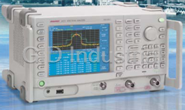
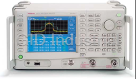
Advantest U3741 Spectrum Analyzer, 9.00 kHz ~ 3.00 GHz frequency with 100 Hz ~ 1 MHz resolution bandwidth
Part Number
U3741
Price
Request Quote
Manufacturer
ADVANTEST
Lead Time
Request Quote
Category
SPECTRUM ANALYZERS
Features
- Average display noise level: -155 dBm/Hz@1 GHz, pre-amp ON
- Better measuring speed due to high-speed processing (twice as fast as its predecessor)
- Built-in 3 GHz/8 GHz pre-amp standard
- Continuous operation of up to 2.5 hours with the battery pack
- Dramatically improved power measurement accuracy for digitally modulated signals
- Lightweight and compact design, with a maximum weight of only 5.6 kg
- Option available for measurement of phase noise characteristics
- Tracking generator covering a frequency range of 100 kHz to 3 GHz/6 GHz
Datasheet

Extracted Text
Spectrum Analyzers U3741/3751 Compact Design with High Performance Pioneering 3 GHz/8 GHz Spectrum Analyzers are Now Available! ● Better measuring speed due to high-speed processing The U3741/3751 portable spectrum analyzer (twice as fast as its predecessor) supports a great range of applications, from ● Dramatically improved power measurement accuracy use on production lines to system installation for digitally modulated signals and maintenance. Its digital IF enables dramatic ● Built-in 3 GHz/8 GHz pre-amp standard ● Average display noise level: improvements in power measurement accuracy -155 dBm/Hz@1 GHz, pre-amp ON for digitally modulated signals. Moreover, the ● Tracking generator covering a frequency range of U3741/3751 provides twice the throughput of its 100 kHz to 3 GHz/6 GHz predecessor. A light and compact 3 GHz/8 GHz ● Option available for measurement of phase noise characteristics spectrum analyzer, the U3741/3751 provides ba- ● Lightweight and compact design, with a maximum sic performance reliably and at a low cost. weight of only 5.6 kg ● Continuous operation of up to 2.5 hours with the battery pack U3741/ 3751 Web Demonstration Please access to the http://www.advantest.co.jp/en-index.shtml and click on the following links. PRODUCTS & SUPPORT Electronic Measuring Instruments Products U3751 2 U3741/3751-4E Jun. ’10 Soft-key block 6.5-inch color liquid Extension-key block crystal display (LCD) Exclusive function keys Front Panel Data Entry Main function keys RF INPUT DC INPUT POWER CAL OUT Control keys Battery mount Operation with an external USB TG OUT Mount for the battery pack DC power supply PHONE Output file data to USB Tracking generator (battery sold separately) +11 VDC to +17 VDC Earphone jack for memory or a USB printer (option) demodulated Image files: PNG, BMP AM/FM audio Setting files: BIN, XML GPIB Rear Panel IF OUT 21.4-MHz IF signal output VIDEO Output to an external VGA EXT TRIG USB monitor EXT REF LAN Standard signal input Control and remote operation, for external reference utilizing an external PC Option Guide Main unit support Product name Model number Overview U3741 U3751 1ch 2ch 1ch 2ch Addition of RF INPUT2 (9 kHz to 3 GHz) 2 Channel input (50 Ω) OPT.10 Individual RF measurement with RF INPUT 1 and RF INPUT 2 Addition of CISPR bandwidth for EMI measurement EMC filter OPT.28 RBW (6 dB Down): 200 Hz, 9 kHz,120 kHz, 1 MHz High-purity spectrum analysis Spectrum analysis with -102 dBc/Hz @ 10 kHz offset (Typical) OPT.70/71 Addition of RBW 30 Hz (1 ch/2 ch) OPT.70 OPT.71 OPT.70 OPT.71 2) Frequency range: 100 kHz to 3 GHz Tracking generator (3 GHz) OPT.76 Output level range: 0 to -60 dBm 2) Frequency range: 100 kHz to 6 GHz Tracking generator (6 GHz) OPT.77 Output level range: 0 to -30 dBm RF INPUT 2 (9 kHz to 2.2 GHz) in addition to OPT.15 2 Channel input (75 Ω) OPT.11 Individual RF measurement with RF INPUT 1 and RF INPUT 2 RF INPUT: 75 Ω (100 kHz to 2.2 GHz) For CATV and TV 1 Channel input (75 Ω) OPT.15 picture signal measurement. Channel table data installed. Frequency range: 100 kHz to 2.2 GHz. Tracking generator (2.2 GHz) OPT.75 Output level range: 107 to 47 dBµV High-stability frequency Reference oscillator with an aging rate of OPT.20 -8 -7 reference source ± 2 x 10 /day, ±1 x 10 /year Analyze the basic parameter of RF signal on a time domain (CBW: 3MHz) Time-domain analysis (1 ch/2 ch) OPT.53/54 (amplitude/phase/frequency/FFT/IQ/IQ output) OPT.53 OPT.54 OPT.53 OPT.54 Wide-band time-domain Analyze the basic parameter of RF signal on a time domain (CBW: 40MHz) OPT.55/56 (amplitude/phase/frequency/FFT/IQ/IQ output) OPT.55 OPT.56 OPT.55 OPT.56 analysis (1 ch/2 ch) Available 1) The options of 50 Ω series and 75 Ω series cannot be installed simultaneously. 2): One must be selected from OPT.76/77. Not available U3741/3751-4E Jun. ’10 3 1) 1) Commons 75 Ω series 50 Ω series Compact Design with High Performance 5-minute warm-up time High throughput With the U3741/3751, warm-up time has been reduced to a scant This spectrum analyzer delivers data transfer speed superior to that 5 minutes (at an ambient temperature of 20 to 30°C). This short- of its predecessor. While the previous model delivered 875 ms, the ened period virtually eliminates pre-warming time as a considera- U3741/3751 boasts a speed of 350 ms: double the system through- *2 *3 tion, and permits quick and accurate measurement. put (using the GPIB interface) . This faster speed contributes to a significant reductions to cost of test on production lines and in similar applications. 5 U3741/3751 min. U3741/3751 Our conventional model Our conventional model Measuring time Time Improvements in overall accuracy Standard USB (1.1) interface Digitized IF sections and innovative circuit technology dramatically Screenshots in BMP or PNG format can easily be sent via USB improve absolute power measurement accuracy. external memory. Users can easily store data, and easily paste mea- surement data into reports. ±0.8 dB (10 MHz to 3 GHz: U3741/3751) ±1.0 dB (3 to 8 GHz: U3751) ADC Digital RBW Digital Det RF Input Digital IF Block *1 Up to 2.5 hours of nonstop battery-driven operation Compact design The spectrum analyzer uses one of three power systems: AC (100 At about half the size of its predecessor, this spectrum analyzer V/200 V), DC (+11 V to +17 V), or the battery pack. This flexi- offers a compact design while maintaining the same level of func- bility enables measurement in a variety of applications, whether in tionality. Its form factor gives it portability, enabling it to be used the factory or in the field. anywhere. *1: Typical value at room temperature, without options Extensive array of measurement functions *2: Twice that of its predecessor Measurement functions include Channel Power, Total Power, *3: Sample case where the frequency and span are specified, and the channel power measurement Avg Power, OBW, ACP, Spurious measurement, Harmonics mea- result is transferred surement, IM measurement, Noise/Hz calculation functions, multi-marker (10 markers), delta marker, peak marker functions, a channel setting function, and a 3-trace simultaneous sampling function. 4 U3741/3751-4E Jun. ’10 Stable measurement Measurement Functions RMS Average, essential for power measurement Pre-Amp covering the 3 GHz/8 GHz bandwidth Power tends to be spread over a wide frequency range, and the peak The U3741/3751 contains as standard a pre-amp that covers all factor tends to be higher in digital modulation, with it’s expanded frequency bands. In the analysis of faint signals, its input sensitiv- communication capacity. The U3741/3751 allows precise power ity can be equivalent to that of high-end models. Also, it effec- measurements by determining the effective values (RMS values) tively compensates for the loss from the antenna when measuring from instantaneous power values obtained in high-speed sampling radio signals in an outdoor environment. and translating them into a power spectrum. This method also enables measurement reproducibility of 0.01 dB in power mea- surement of digitally modulated signals. Example of ISDB-T Example of high- Channel Power sensitivity measurement measurement in high-sensitivity mode Built-in frequency counter with 1-Hz resolution USER keys Frequency can be accurately measured by simply positioning the An arbitrary key can be selected from the hierarchical function cursor on the target spectrum selected from multiple spectral lines. keys and assigned to a USER function. Users can thus configure The U3741/3751 is indispensable for measuring the carrier wave their own, original setup for operations by assigning frequently frequency in a general multi-carrier system. used functions to specific software keys. Example of multi- Example of carrier signal frequency user function measurement assignment Zoom function Spectrum emission mask function The measuring window and F-F mode can facilitate analysis of a Using tools such as a spectrum mask and limit line to judge specific signal in broadband measurement. Also, RBW can be PASS/FAIL is effective at improving production line throughput changed independently, enabling high-speed measurement of the for digital appliances. Using the spectrum emission mask (SEM) target signal in both broadband and narrowband. A variety of function can facilitate measurement for standards such as wireless other signal analysis functions are also available, including those in LAN. F-T mode or T-T mode. Example of two-screen sample from measurement in Example of S.E.M. broadband and measurement for narrowband wireless LAN U3741/3751-4E Jun. ’10 5 User-friendly and Convenient Functions Gated Sweep function Gated Sweep OFF A radar or TDMA communication system controls its output transmission by turning the power on/off intermittently. To mon- itor the power spectrum during transmission, the Gated Sweep function is effective at analyzing the spectrum only when the signal is present and over only the area chosen. This function also includes an IF trigger that does not require synchronized signals. Gated Sweep ON EXT TRIG Synchronized signals RF INPUT Burst Signal Ideal for remote operation/monitoring via a LAN This spectrum analyzer is equipped with a 10/100BASE-T LAN port as standard, so it can be operated remotely from an external PC. It can be installed in an unattended radio transmission station, and remotely operated and monitored from another station. LAN PC Screen of remote operation/monitoring from an external PC via LAN PC Server Searching for the location of a fault in a coaxial cable When used with its tracking generator option and the sample soft- ware for an external PC, the U3741/3751 can measure the dis- tance to the failure point (open/short) in a coaxial cable. This application permits this distance to be measured from one end of the coaxial cable. GPIB TG OUT RF INPUT Screen for measuring the distance to a cable failure point PC with sample software Cable Power splitter 6 U3741/3751-4E Jun. ’10 Extensive Array of Options 2 Channel Input OPT.10 (50 Ω)/11 (75 Ω) Two-channel input option (OPT.10/OPT.11) offers two inde- pendent lines of RF input. Various measurement conditions including measuring frequency and spans can be set indepen- dently for each RF input. High-speed process by the parallel processing • Simultaneous measurement of standard items (Channel power and OBW, etc.) • Reduction in time by two-piece simultaneous measurement • Simultaneous measurement of the different system, etc. Simultaneous measurement of Channnel Power and OBW • Simultaneous measurement of different frequency (1 GHz or less and micro-wave) etc. at EMC measurement Applications only possible for a two-channel spectrum analyzer • Timing measurement between two channels by the synchronized sweep and synchronized trigger • Simultaneous spectrum observation of the different frequency by the synchronized sweep when sweeping time is the same • Simultaneous observation of the whole/part by the synchronized trigger • Simultaneous monitoring of input/output devices Simultaneous measurement of the broadband/narrowband by the synchronized sweep Allocating Connectors on Front Panel (for U3741) TG OUTPUT (OPT.76) RF INPUT 1 (standard equipment) RF INPUT 2 (OPT.10) Simultaneous measurement of input/output for feed-forward amp FSK signal measurement (required with OPT.54) Timing measurement of TPMS by the synchronized trigger U3741/3751-4E Jun. ’10 7 Extensive Array of Options Time-Domain Analysis OPT.53 (1 ch)/54 (2 ch) Wide-Band Time-Domain Analysis OPT.55 (1 ch)/56 (2 ch) By installing this option in addition to the function of the conven- tional sweeping-type spectrum analyzer, a the time-domain analysis basic functions is added at low-cost. Signal observation based on a domain different from sweeping-type spectrum analyzer • Change in frequency over time by Freq. vs. Time analysis (ex. analysis of FSK signals, such as keyless entry and TPMS) • Change in phase over time by Phase vs. Time analysis • Change in power over time by Power vs. Time analysis High sensitivity measurement by FFT (RBW 1Hz, -160dBm/Hz (typ)) • High resolution (equivalent of 1 Hz RBW) high sensitivity measurement by FFT Time-domain analysis for two singnals (OPT.54/56) The time-domain basic analysis function in the range of 9 kHz to 8 GHz (on main body) can be installed simultaneously for 2 chan- nels. Unique analysis functions, such as Freq. vs Time during input and output are realized. Wide-band time-domain analysis (OPT.55/56) In the frequency ranges of 9 kHz to 8 GHz (on main body), time- domain analysis for up to the maximum measurement bandwidth 40 MHz is possible. Measurement using the time-domain basic analysis function FREQ. vs. Time measurement of the 4 value FSK FFT Spectrum Freq. vs. Time Radar wave measurement (OPT.55 for Wide-band time-domain analysis) Power vs. Time Phase vs. Time Spectrum Analyzer U3700 Series MIX. BPF ADC RBW Power DET. RF Input I/Q FFT Display LO Detector Spectrum Power Vs. Time Switching Sample Rate Waveform Control Memory Display Download I/Q data Freq. Vs. to external PC Time OPT.53 Phase Vs. Time-Domain Time Analysis Option IQ Waveform GPIB/LAN 8 U3741/3751-4E Jun. ’10 Extensive Array of Options High-Purity Spectrum Analysis OPT.70 (1 ch)/71 (2 ch) -70 Phase noise measurement is indispensable to evaluation of the -80 @ 2 GHz characteristics of high-frequency oscillation circuits or modules. @ 5 GHz -90 The high-purity spectrum analysis option offered with the U3741/3751 can improve the phase noise measurement perfor- -100 mance of the spectrum analyzer. Because the performance can be -110 selected, selecting the most suitable spectrum analyzer for the device under test (DUT) is simple. At the same time, the added -120 resolution bandwidth of 30 Hz enables reduction of the display -130 average noise level and analysis in a high dynamic range. -140 2 channel-inputs option (OPT.10/11) is required for OPT.71 installation. 110 100 1,000 10,000 Carrier Offset Frequency [kHz] Phase noise characteristic graph (representative values) Tracking Generator OPT.75/76/77 OPT.76 Output impedance: 50 Ω Generates synchronized signals for frequency sweeps by the spec- trum analyzer. Output frequency range: 100 kHz to 3 GHz OPT.77 Output impedance: 50 Ω OPT.75 Output impedance: 75 Ω Output frequency range: 100 kHz to 6 GHz Output frequency range: 100 kHz to 2.2 GHz Functions for evaluating frequency characteristics The normalize function enables direct measurement of cable loss and filter characteristics. The frequency offset function of the tracking generator enables measurement of frequency characteris- tics and conversion loss characteristics of mixers and other fre- quency conversion devices. Characteristics of a mixer + filter Characteristics of a filter RF INPUT TG OUT Frequency conversion device Measurement of mixer frequency conversion loss characteristics Fin Fout Lo Function for return loss measurement The SWR bridge can be used to measure reflection characteristics of an antenna or filter. It can determine the return loss and evaluate the VSWR. RF INPUT TG OUT SWR bridge Filter return loss measurement Antenna, filter, etc. U3741/3751-4E Jun. ’10 9 Phase Noise [dBc/Hz] Extensive Array of Options and Accessories High-Stability Frequency Reference Source OPT.20 Frequency of the high frequency signal was conventionally In a spectrum analyzer, just by pointing the marker at the spec- counted with a frequency counter. However, multi-carrier method trum separated as a sine wave of CW, not only the frequency is often employed for the recent communication system which counting but also faint signal level counting is possible. OPT.20 uses high frequency signals which contains multiple frequency improves the aging stability of the standard oscillator which deter- components, a frequency counter cannot count the frequency cor- mines the frequency counter accuracy of a spectrum analyzer. rectly. Therefore, the frequency counter of the spectrum analyzer attracts attention as an essential function. Aging rate -6 Standard ±2 x 10 /year -8 -7 OPT.20 ±2 x 10 /day, ±1 x 10 /year EMC Filter OPT.28 Option 28 adds 6 dB RBW CISPR bandwidths for EMI measure- ment of 200 Hz, 9 kHz, 120 kHz, and 1 MHz. A broadband sweep by the spectrum analyzer is very effective at measuring noise emitted from electrical devices. Installing OPT.28 allows measure- ment in CISPR-specified bandwidths. It enables simple, fast mea- surement using the Positive peak detector and Max Hold, which makes it effective at compensating for emitted noise. It guarantees an impulse bandwidth accuracy of 1 MHz. This capability con- forms to the standard for noise measurement of 1 GHz or above. Measurement using EMI sample software Accessories Transit case Many accessories are available, including an easy-to-carry transit case and a battery pack, useful for field work. Carrying bag DC power cable Charger 50Ω–75Ω Battery pack impedance converter 10 U3741/3751-4E Jun. ’10 Specifications Amplitude range Measurement range: Displayed average noise level to +30 dBm Frequency Displayed average noise level to 134 dBµV Frequency range (with the OPT.15 installed) U3741: 9 kHz to 3 GHz, Maximum safe input level: Attenuator ≥ 10 dB 9 kHz to 2.2 GHz (with the OPT.15 installed) Pre-Amp OFF: +30 dBm, 134 dBµV (with the OPT.15 installed) Pre-Amp: 10 MHz to 3 GHz, Pre-Amp ON: +13 dBm, 120 dBµV (with the OPT.15 installed) 10 MHz to 2.2 GHz (with the OPT.15 installed) U3741: ±50 VDC max. Synchronizable U3751: ±15 VDC max. frequency range: 9 kHz to 3 GHz U3751: 9 kHz to 8 GHz Input attenuator range: 0 to 50 dB (10 dB steps) Frequency band: 9 kHz to 3.1 GHz (band 0), Display range: 100/50/20/10/5 dB, linear 3 GHz to 8 GHz (band 1) Pre-Amp: 10 MHz to 8 GHz Scale unit: dBm, dBmV, dBµV, dBµVemf, dBpW, W, V Frequency reading Reference level accuracy: ± (marker read value x frequency reference setting range: -140 to +40 dBm accuracy + span x span accuracy + residual FM) -31.2 to 148.8 dBµV (with the OPT.15 installed) Frequency reference stability Detection mode: Normal, Positive peak, Negative peak, -6 Aging rate: ±2 x 10 /year Sample, RMS, and Average -6 Temperature stability: ±2.5 x 10 (0 to 50°C) Frequency counter: Resolution bandwidth ≤100 kHz, Amplitude accuracy span ≤100 MHz, signal level: S/N >50 dB Calibration signal Resolution: 1 Hz to 1 kHz Frequency: 20 MHz Accuracy: ± (counter read value x frequency reference Level: -20 dBm (75 Ω, with the OPT.15 installed) accuracy + residual FM + 1 LSB) Accuracy: ±0.3 dB, ±0.4 dB (with the OPT.15 installed) Frequency stability Scale display accuracy Residual FM (zero/span): < 60 Hzp-p/100 ms (internal frequency reference) Log: ±0.5 dB/10 dB, ±0.5 dB/80 dB, ±0.2 dB/1 dB Frequency span Overall amplitude Range: 5 kHz to Full, zero span accuracy: After calibration, with the pre-amp OFF, 1 kHz to Full, zero span and at a temperature ranging from 20 to 30°C (with the OPT.70 installed) Input attenuator 10 dB Accuracy: < ±1% U3741: Reference level 0 dBm, Spectrum purity: -85 dBc/Hz (offset 10 kHz, span < 200 kHz) input signal level -10 to -50 dBm ±1.0 dB (9 kHz to 3 GHz) Resolution bandwidth ±0.8 dB (10 MHz to 3 GHz) Range: With the OPT.15 installed: Reference level 108.8 dBµV U3741: 100 Hz to 1 MHz (1 to 3 steps) Input signal level 98.8 to 58.8 dBµV 30 Hz to 1 MHz (with the OPT.70/71 installed) ±2.1 dB (9 kHz to 2.2 GHz) U3751: 100 Hz to 3 MHz (1 to 3 steps) ±0.9 dB (10 MHz to 2.2 GHz) 30 Hz to 3 MHz (with the OPT.70/71 installed) U3751: Reference level 0 dBm, Accuracy: < ±12% input signal level -10 to -50 dBm Video bandwidth range: 10 Hz to 3 MHz (1 to 3 steps) Image suppression OFF ±1.5 dB (9 kHz to 10 MHz) ±0.8 dB (10 MHz to 3.1 GHz) Sweep ±1.0 dB (3.1 GHz to 8 GHz) Sweep time Setting range: 20 ms to 1000 s (spectrum mode) 50 µs to 1000 s (zero span) Accuracy: < ±2% (zero span) Sweep mode: Continuous, single, gated Trigger function Trigger source: Free run, video, external, IF U3741/3751-4E Jun. ’10 11 Dynamic range Inputs/outputs Displayed average RF input noise level: Reference level < -45 dBm (63.8 dBµV, Connector: N-type female with the OPT.15 installed) Impedance: 50 Ω (nominal) Resolution bandwidth 100 Hz 75 Ω (nominal, with the OPT.15 installed) U3741: Frequency 10 MHz to 3 GHz VSWR: Input attenuator ≥ 10 dB Pre-Amp OFF: -123 dBm + 2f (GHz) dB (f < 2.5 GHz) U3741: < 1.5 : 1 -123 dBm + 2.5f (GHz) dB (f ≥ 2.5 GHz) < 1.6 : 1 (with the OPT.15 installed) -12 dBµV + 2f (GHz) dB (f ≤ 2.2 GHz, U3751: < 1.7 : 1 (10 MHz ≤ Frequency ≤ 3.0 GHz) with the OPT.15 installed) < 2.0 : 1 (Frequency > 3.0 GHz) Pre-Amp ON: -138 dBm + 3f (GHz) dB Calibration signal output -27 dBµV + 3f (GHz) dB Connector: BNC female (with the OPT.15 installed) Impedance: 50 Ω (nominal) U3751: Frequency 10 MHz to 8 GHz 75 Ω (nominal, with the OPT.15 installed) Pre-Amp OFF: -123 dBm + 2f (GHz) dB (f ≤ 3.1 GHz, band 0) Frequency: 20 MHz -122 dBm + 1f (GHz) dB (f ≥ 3 GHz, band 1) Level: -20 dBm Pre-Amp ON: -138 dBm + 3f (GHz) dB (f ≤ 3.1 GHz, band 0) -139 dBm + 1.3f (GHz) dB (f ≥ 3 GHz, band 1) Frequency reference input Connector: BNC female 1 dB gain compression Impedance: 50 Ω (nominal) U3741: Frequency > 20 MHz Frequency (MHz): 1, 1.544, 2.048, 5, 10, 12.8, 13, 13.824, 14.4, Pre-Amp OFF: > -5 dBm 15.36, 15.4, 16.8, 19.2, 19.44, 19.6608, > 102 dBµV (with the OPT.15 installed) 19.68, 19.8, 20, 26 Pre-Amp ON: > -25 dBm Level: 0 to +16 dBm > 82 dBµV (with the OPT.15 installed) U3751: Frequency > 20 MHz External trigger input Pre-Amp OFF: > -8 dBm Connector: BNC female Pre-Amp ON: > -25 dBm Impedance: 10 kΩ (nominal), DC coupling Level: 0 to +5 V Second harmonic distortion U3741: <-70 dBc (Pre-Amp OFF, Frequency > 20 MHz, 21.4-MHz IF output Mixer input level -30 dBm (77 dBµV, with Connector: BNC female the OPT.15 installed)) Impedance: 50 Ω (nominal) U3751: <-70 dBc (Pre-Amp OFF, Frequency > 200 MHz, Level: Approx. mixer input level + 10 dB Mixer input level -40 dBm) (at a frequency of 20 MHz) <-75 dBc (typ., Pre-Amp OFF, Frequency Battery mount > 300 MHz, Mixer input level -30 dBm) Connector: AntonBauer QR mount Third order intermodulation distortion External DC power input U3741: < -60dBc (Pre-Amp OFF, Mixer input level Connector: XLR-4 -20 dBm (88.8 dBµV, with the OPT.15 Voltage range: +11 to +17 V installed), Frequency > 10 MHz, 2 signal separation > 200 kHz) GPIB: IEEE-488 bus connector U3751: < -50 dBc (Pre-Amp OFF, Mixer input level USB: USB 1.1 -20 dBm, Frequency 10 MHz to 8 GHz, Video output connector: D-sub15 pin female 2 signal separation > 200 kHz) LAN connector: RJ45 type, 10/100 base-T Audio output: Small monophonic jack Image/multiple/out of band response U3741: < -60 dBc (Mixer input level -20 dBm (88.8 dBµV, with General specifications the OPT.15 installed)) Operating environment range: Ambient temperature: 0 to + 50°C U3751: < -60 dBc Humidity: RH 85% or less (no condensation) (Mixer input level -30 dBm, Storage environment range: -20 to +60°C, RH 85% or less Image suppression ON) AC power input: Automatic switching to 100 VAC or 200 VAC Residual response 100 V: 100 to 120 V, 50/60 Hz U3741: < -90 dBm (Frequency > 1 MHz , Pre-Amp OFF) 200 V: 220 to 240 V, 50/60 Hz < 21 dBµV (with the OPT.15 installed) DC power input: DC + 11 V to +17 V U3751: < -80 dBm Power consumption: 100 VA or less (AC operation) (Frequency 10 MHz to 8 GHz, Pre-Amp OFF) 70 W or less (DC operation) Mass U3741: 5 kg or less (without option) U3751: 5.6 kg or less (without option) External dimensions (W x H x D): Approx. 308 x 175 x 209 mm (not including protruding parts) Approx. 337 x 190 x 307 mm (including the handle and feet) 12 U3741/3751-4E Jun. ’10 OPT.10 2 Channel input (50 Ω, 3 GHz) OPT.55/56 Wide-band time-domain analysis (1 ch/2 ch) Cross talk between input RF range: Follows the U3741/3751. ✽1) channels (between RF input RF amplitude range: Noise level to +30 dBm 1 and RF input 2 ): <-90 dBc (Input level -10 dBm, Input Wave recording method: I/Q vector time waveform attenuator 0 dB, Preamplifier off) Measuring bandwidth (CBW):100 Hz to 30 MHz (1 to 3 steps), 40 MHz RF input 2 IQ sampling rate: 500 Hz (BW 100 Hz) to 65 MHz (BW 40 MHz) Connector: N type female IQ waveform recording time: 120 msec (BW 40 MHz) to 1000 sec (BW 100 Hz) Impedance: 50 Ω (nominal) Number of IQ waveform VSWR: <1.5 : 1 (Input attenuator > 10 dB) recording samples: 8 M samples (I/Q) External trigger input: An external trigger input can be selected as ✻1) The noise level follows the dynamic range of the U3741/3751. a trigger input of RF input 2 when installing the OPT.10. The input connector is only 1 OPT.70/71 High-purity spectrum analysis (1 ch/2 ch) system. 21.4 MHz IF output: Only IF output which supports RF input 1, Frequency span when installing the OPT.10. Range: 1 kHz to Full, zero span Accuracy: < ±1% Except for all items mentioned above, the frequency, sweep, amplitude range, amplitude accuracy, dynamic range, input/output, and performance of specifications Resolution bandwidth follow the standard specifications of the RF input 1 option of the U3741 spectrum Range: U3741: 30 Hz to 1 MHz (1 to 3 steps) analyzer. U3751: 30 Hz to 3 MHz (1 to 3 steps) Accuracy: < ±12% OPT.11 2 Channel input (75 Ω, 2.2 GHz) Spectrum purity: ≤ -98 dBc/Hz (offset 10 kHz, span ≤ 1 MHz) -102 dBc/Hz (Typical) Cross talk between input channels (between RF input Displayed average 1 and RF input 2 ): <-90 dBc (Input level 98.8 dBµV, Input noise level: Reference level < -45 dBm, attenuator 0 dB, Preamplifier off) Resolution bandwidth 30 Hz RF input 2 U3741: Frequency 10 MHz to 3 GHz Connector: N type female Pre-Amp OFF: -126 dBm + 2f (GHz) dB (f < 2.5 GHz) Impedance: 75 Ω (nominal) -126 dBm + 2.5f (GHz) dB (f ≥ 2.5 GHz) VSWR: <1.5 : 1 (Input attenuator > 10 dB) Pre-Amp ON: -141 dBm + 3f (GHz) dB External trigger input: An external trigger input can be selected as U3751: Frequency 10 MHz to 8 GHz a trigger input of RF input 2 when installing Pre-Amp OFF: -126 dBm + 2f (GHz) dB (f ≤ 3.1 GHz, band 0) the OPT.11. The input connector is only 1 -125 dBm + 1f (GHz) dB (f ≥ 3 GHz, band 1) system. Pre-Amp ON: -141 dBm + 3f (GHz) dB (f ≤ 3.1 GHz, band 0) 21.4 MHz IF output: Only IF output which supports RF input 1, -142 dBm + 1.3f (GHz) dB (f ≥ 3 GHz, band 1) when installing the OPT.11. Except for all items mentioned above, the frequency, sweep, amplitude range, OPT.75 Tracking generator (75 Ω, 2.2 GHz) amplitude accuracy, dynamic range, input/output, and performance of specifications Frequency range: 100 kHz to 2.2 GHz follow the standard specifications of the RF input 1 option of the U3741 + OPT.15 spectrum analyzer. Frequency offset Range: 0 Hz to 1 GHz Accuracy: ±300 Hz OPT.20 High-stability frequency reference source Resolution: 1 kHz Frequency reference stability -8 Output level range: 107 to 47 dBµV (0.5 dB steps) Aging rate: ±2 x 10 /day -7 ±1 x 10 /year Output level accuracy: ±0.5 dB (20 MHz, 97 dBµV, +20 to +30°C) -8 Warm-up drift: ±5 x 10 (+25°C, 10 minutes after power-on) -8 Output level flatness: Using 20 MHz and 97 dBµV as a reference Temperature stability: ±5 x 10 ( 0 to +40°C, with reference to 25°C) ±1.0 dB (1 MHz to 1 GHz) ±1.5 dB (100 kHz to 2.2 GHz) OPT.28 EMC filter Output level switch error: Using 20 MHz and 97 dBµV as a reference 6 dB bandwidth: 200 Hz, 9 kHz, 120 kHz, 1 MHz ±1.0 dB (1 MHz to 1 GHz, 107 to 47 dBµV) Bandwidth accuracy: < ±10% ±2.0 dB (1 MHz to 2.2 GHz, 107 to 47 dBµV) Frequency offset OFF: ±3.0 dB (100 kHz to 2.2 GHz, 107 to 77 dBµV) ±4.0 dB (100 kHz to 2.2 GHz, 76.5 to 47 dBµV) OPT.53/54 Time-domain analysis (1 ch/2 ch) Frequency offset ON: ±5.0 dB (100 kHz to 2.2 GHz) RF range: Follows the U3741/3751. Output spurious: Output level 97 dBµV✽1) RF amplitude range: Noise level to +30 dBm Harmonic: < -15 dBc (100 kHz to 1 MHz) Wave recording method: I/Q vector time waveform < -20 dBc (1 MHz to 2.2 GHz) Measuring bandwidth (CBW):100 Hz to 3 MHz (1 to 3 steps) Non-harmonic: < -20 dBc (Frequency offset OFF) IQ sampling rate: 713 Hz (BW 100 Hz) to 21.4 MHz (BW 3 MHz) IQ waveform recording time: 49 msec (BW 3 MHz) to 1000 sec (BW 100 Hz) TG leakage: < 31 dBµV (Input attenuator 0 dB) Number of IQ waveform Output impedance: 75 Ω (nominal) recording samples: 1 M samples (I/Q) VSWR: ≤ 2.0 : 1 (Output level ≤ 97 dBµV) ✻1) The noise level follows the dynamic range of the U3741/3751. Maximum allowable level: 117 dBµV, ±10 VDC U3741/3751-4E Jun. ’10 13 OPT.76 Tracking generator (50 Ω, 3 GHz) Ordering information Frequency range: 100 kHz to 3 GHz Main unit Spectrum analyzer: U3741 Frequency offset U3751 Range: 0 Hz to 1 GHz Accuracy: ±300 Hz Accessories Resolution: 1 kHz Operating manual (CD): BU3700S Power cable: A01412 Output level range: 0 to -60 dBm (0.5 dB steps) Input cable: A01037-0300 Output level accuracy: ±0.5 dB (20 MHz, -10 dBm, +20 to +30°C) With the OPT.15 installed: A01045 N-BNC adapter: JUG-201A/U Output level flatness: Using 20 MHz and -10 dBm as a reference With the OPT.15 installed: BA-A165 ±1.0 dB (1 MHz to 1 GHz) NC-F adapter (with the OPT.15 installed): NCP-NFJ ±1.5 dB (100 kHz to 3 GHz) Ferrite core: ESD-SR-120, E04SR150718 Output level switch error: Using 20 MHz and -10 dBm as a reference ±1.0 dB (1 MHz to 1 GHz, 0 to -60 dBm) Options ±2.0 dB (1 MHz to 2.6 GHz, 0 to -60 dBm) 2 Channel input (50 Ω, 3 GHz): OPT.10 Frequency offset OFF: ±3.0 dB (100 kHz to 3 GHz, 0 to -30 dBm) 2 Channel input (75 Ω, 2.2 GHz): OPT.11 ±4.0 dB (100 kHz to 3 GHz, -30.5 to -60 dBm) 1 Channel input (75 Ω): OPT.15 Frequency offset ON: ±5.0 dB (100 kHz to 3 GHz) High-stability frequency reference source: OPT.20 EMC filter: OPT.28 Output spurious: Output level -10 dBm Time-domain analysis (1 ch): OPT.53 Harmonic: < -15 dBc (100 kHz to 1 MHz) Time-domain analysis (2 ch): OPT.54 < -20 dBc (1 MHz to 3 GHz) Wide-band time-domain analysis (1 ch): OPT.55 Non-harmonic: < -20 dBc (Frequency offset OFF) Wide-band time-domain analysis (2 ch): OPT.56 TG leakage: < -80 dBm (Input attenuator 0 dB) High-purity spectrum analyzsis (1 ch): OPT.70 High-purity spectrum analyzsis (2 ch): OPT.71 Output impedance: 50 Ω (nominal) Tracking generator (75 Ω, 2.2 GHz): OPT.75 VSWR: ≤ 2.0 : 1 (Output level ≤ -10 dBm) Tracking generator (50 Ω, 3 GHz): OPT.76 Maximum allowable level: +10 dBm, ±10 VDC Tracking generator (50 Ω, 6 GHz): OPT.77 Accessories ✽2) OPT.77 Tracking generator (50 Ω, 6 GHz) Japanese operating manual (printed manual): JU3700S English operating manual (printed manual): EU3700S Frequency range: 100 kHz to 6 GHz Battery pack: A870008 Output level range: 0 to -30 dBm (0.5 dB step) Charger: A870009 Output level accuracy: ≤ ±0.5 dB (20 MHz, -10 dBm, +20 to +30°C) 75 Ω input impedance converter: ZT-130NC Output level flatness: 20 MHz on -10 dBm criterion, at +20 to +30°C DC power cable: A114020 ≤ ±1 dB (1 MHz to 1 GHz) Carrying bag: A129001 ≤ ±1.5 dB (100 kHz to 3.1 GHz) Transit case: A129002 ≤ ±2.0 dB (100 kHz to 6 GHz) Rack mount kit (JIS): A122003 TG leakage: ≤ -80 dBm (input attenuator: 0 dB) Rack mount kit (EIA): A124004 Output impedance: 50 Ω (nominal) 6 GHz VSWR bridge: A199001 VSWR: ≤ 2.0 : 1 (Output level ≤ -10 dBm) Maximum allowable level: +10 dBm, ±10 VDC Note on accessories: The operating manual on the CD is supplied as standard. ✻2) The OPT.77 is not allowed to be installed on the U3741. The printed version of the operating manual is offered as an accessory. A199001 6 GHz VSWR bridge Frequency range: 100 MHz to 6 GHz Directivity: ≥34 dB (100 MHz to 1 GHz) ≥29 dB (1 to 3.8GHz) ≥25 dB (3.8 to 6GHz) Maximum input power: +15 dBm (Input Port) DC voltage: ±30 VDC ( Test Port) Connector: SMA (female) External dimensions (W x H x D): Approx. 103 x 35 x 20 mm Mass: 100 g or less 14 U3741/3751-4E Jun. ’10 Sample software to be downloaded free from homepage ADVANTEST provides various kinds of sample software shown below : • Useful sample software for EMI measurement and Radio waves monitor, etc. • Module software with source code to control a Spectrum analyzer for developers. http://www.advantest.co.jp/en-index.shtml PRODUCTS & SUPPORT Electronic Measuring Instruments Products U3741 or U3751 Sample Software EMI measurement software (2 ch) Radio waves monitor (1 ch/2ch) Please refer to product manual for complete system specifications. Specifications may change without notification. U3741/3751-4E Jun. ’10 15 http://www.advantest.co.jp ADVANTEST CORPORATION Shin-Marunouchi Center Building, 1-6-2 Marunouchi, Chiyoda-ku, Tokyo 100-0005, Japan Phone: +81-3-3214-7500 ©2007 ADVANTEST CORPORATION Printed in Japan Bulletin No.U3741/3751-SI4E-234 Jun. ’10 S
Frequently asked questions
What makes Elite.Parts unique?

What kind of warranty will the U3741 have?
Which carriers does Elite.Parts work with?
Will Elite.Parts sell to me even though I live outside the USA?
I have a preferred payment method. Will Elite.Parts accept it?


What they say about us
FANTASTIC RESOURCE
One of our top priorities is maintaining our business with precision, and we are constantly looking for affiliates that can help us achieve our goal. With the aid of GID Industrial, our obsolete product management has never been more efficient. They have been a great resource to our company, and have quickly become a go-to supplier on our list!
Bucher Emhart Glass
EXCELLENT SERVICE
With our strict fundamentals and high expectations, we were surprised when we came across GID Industrial and their competitive pricing. When we approached them with our issue, they were incredibly confident in being able to provide us with a seamless solution at the best price for us. GID Industrial quickly understood our needs and provided us with excellent service, as well as fully tested product to ensure what we received would be the right fit for our company.
Fuji
HARD TO FIND A BETTER PROVIDER
Our company provides services to aid in the manufacture of technological products, such as semiconductors and flat panel displays, and often searching for distributors of obsolete product we require can waste time and money. Finding GID Industrial proved to be a great asset to our company, with cost effective solutions and superior knowledge on all of their materials, it’d be hard to find a better provider of obsolete or hard to find products.
Applied Materials
CONSISTENTLY DELIVERS QUALITY SOLUTIONS
Over the years, the equipment used in our company becomes discontinued, but they’re still of great use to us and our customers. Once these products are no longer available through the manufacturer, finding a reliable, quick supplier is a necessity, and luckily for us, GID Industrial has provided the most trustworthy, quality solutions to our obsolete component needs.
Nidec Vamco
TERRIFIC RESOURCE
This company has been a terrific help to us (I work for Trican Well Service) in sourcing the Micron Ram Memory we needed for our Siemens computers. Great service! And great pricing! I know when the product is shipping and when it will arrive, all the way through the ordering process.
Trican Well Service
GO TO SOURCE
When I can't find an obsolete part, I first call GID and they'll come up with my parts every time. Great customer service and follow up as well. Scott emails me from time to time to touch base and see if we're having trouble finding something.....which is often with our 25 yr old equipment.
ConAgra Foods