

 Manufacturers
ADVANTEST R5372
Description
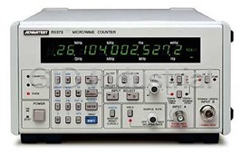
Advantest R5372 Electronic Counter 10 mHz to 18 GHz
Part Number
R5372
Price
Request Quote
Manufacturer
ADVANTEST
Lead Time
Request Quote
Category
PRODUCTS - R
Features
- Digital Comparator Function and Wide Range of Built-In Calculation Functions
- Digital TRAHET Technique
- Wide FM Allowable Range
- Wide Selection
Datasheet

Extracted Text
Electronic Counters 10 mHz to 18 GHz/27 GHz R5372/5373 Wide Selection Digital TRAHET Technique Wide FM Allowable Range Digital Comparator Function and Wide Range of Built-In Calculation Functions (Photo is R5373) R5372/5373 Microwave Frequency Counters Recent research in communications and broadcast systemsMeasurements up to the Microwave and Millimeter- using microwaves in applications such as broadcast satellites, wave Bands telephone circuits and the new field of submillimeter micro- Measurement ranges extend from 10 mHz to 18 GHz for the wave and millimeter-wave communications systems have re- R5372 and 10 mHz to 27 GHz for the R5373. It enables a single sulted in dramatic development in components and practical counter to be used for broadcast satellite, satellite communica- product designs. This research and development work re- tions, pilot-signal measurements for radio equipment and quires highly accurate frequency measurements. Previous many more diverse applications. approaches to measure frequencies in these bands involved the Reciprocal Counting Technique for High-Resolution use of frequency converters or converting oscillators. These Measurements methods, however, were difficult to use as it required trouble- some tuning and calculations to determine the actual fre- The 10 mHz to 10 MHz mode for the A input uses a reciprocal quency. technique that calculates the frequency from the period of the To solve these problems, ADVANTEST has employed a digital input signal, thereby achieving high resolution in a short TRAHET technique to achieve 1 Hz resolution with a gate time counting time. This enables high-resolution measurements of of just one second. It enables not only frequency measurement the pulse width of pulse-modulated signals and of pulse but the application of offset to frequency results and calcula- repetition frequencies. Making a measurement is as simple as tion of standard deviation, ppm, maximum values, minimum setting the required measurement resolution; the rest is auto- values and other useful parameters. In addition, a digital matic with extremely easy selection of number of displayed comparator has been provided and totalizing and measure- digits, counting time and frequency. ments of the carrier frequency of pulse-modulated signals are also possible. Selection Guide 10mHz 1Hz 1MHz 1GHz 10GHz 100GHz 10 mHz to 18 GHz R5372 10 mHz to 27 GHz R5373 Measurement method Reciprocal Direct Counting Digital TRAHET Major applications 174 FM broadcasts and VHF/UHF broadcasts Microwave circuits SHF Broadcasts Broadcast satellite (BS) Submillimeter- wave circuits Communications satellites (CS) 50 GHz commercial radio services Electronic Counters Ideal For Frequency Measurements Over a Wide Band Range R5372/5373 Digital TRAHET Technique for Microwave FrequencyRadio Equipment Frequency Measurements Using an Measurements IF Offset Display The digital TRAHET technique combines the advantages of The R5372/5373 have an IF offset display function which can be the transfer technique which provides relatively high-sensi- used to directly display the received frequency of a radio re- tivity measurements and the heterodyne technique which ceiver. Simply input the IF frequency of the heterodyne receiver provides high resolution. Implementing these under micro- as an offset frequency from the keyboard and measure the local processor control, a dramatic improvement in cost perfor- oscillator frequency to directly display the received frequency. mance can be achieved. The frequency ranges covered are 500 The offset value can be set at any digit down to 0.1 Hz resolution MHz to 18 GHz (R5372), 500 MHz to 27 GHz (R5373). After when setting in MHz units. For local oscillator frequencies heterodyning using the digital TRAHET technique, direct higher than the received frequency, the offset is simply input as counting is used to provide 1 Hz resolu-tion in just 1 second. a negative value. Wide Allowable FM Range Almost all microwave carrier signals are FM modulated by noise and parasitic FM, demanding from a counter the FX R5372/5373 ability to tolerate a wide range of FM. In manual measure- IF;30MHz ments, for a signal of 1.4 GHz or greater, these counters can tolerate ±125 MHz or more. In the range 500 MHz to 1.4 RECEIVER GHz, they can tolerate up to ±25 MHz. For automatic measurements, the tolerance for FM is 10 MHz FL FX=FL+IF p-p in the worst case. Calculation Functions and Digital Comparator Provided as Standard High-Accuracy Frequency Measurements on Radio The R5372/5373 feature a built-in microprocessor which is Receivers used not only to control the measurement system but to simplify operations and perform calculations on measure- ment results as well. FX Using these calculation functions, a moving difference dis- R5372/5373 play, scaling, 8–by–8 digit arithmetic operations and displays of calculated measured values of A/B inputs and B/C inputs RECEIVER are possible. These features greatly enhance versatility. Key setting Description FL IF FX=FL+IF MAX Maximum-value hold Local Frequency MIN Minimum-value hold Δ F Deviation (Defined as the difference between maximum and minimum values) COMP Digital Comparator (GO/NO-GO test)Measurement of Oscillating Frequencies In 1 4 AVG Averaging (10 to 10 samples) Magnetrons For Microwave Ovens δ Standard deviation Since magnetrons in microwave ovens usually employ intermit- ACQ Acquisition mode tent oscillations synched to the power frequency, measurement TR TR4110 Series marker frequency measurement with conventional frequency counters has been extremely diffi- MANL Manual acquisition mode cult. The R5372/5373 have a power sync mode to provide PPM Parts per million accurate synchronization without external apparatus for mea- TOT A A input totalize suring oscillating frequencies. By adjusting the delay knob, the CLR-KB Clear keyboard profile of the oscillating frequencies can also be measured. x, ÷, OFS Arithmetic operation display FM Deviation Measurements Are Simple FPU and STL testing of TV relay equipment require measure- ments of transmitting output and frequencies as well as FM deviation measurements. The ΔF mode can be used to perform Magnetron easy deviation measurements of FM modulated frequencies. Oscillating output Measurement by means of an external trigger signal is also LINE sync signal possible. (Internal) Td Relay Station (STL or FPU) FM Deviation Measurements GATE OUT The R5372/5373 have a wide range of calculation functions Td which greatly simplify FM deviation measurements. By using an external signal to open a gate in sync, the ΔF mode is selected. TG After this, the delay knob can be turned to perform automatic Td : Delay internal calculation of the maximum and minimum values after TG : Gate time measurements are started. By using an external start signal (1 μs min.) synced to an arbitrary amplitude point on a modulated Measurement of oscillating frequencies in magnetrons signal, it is possible to determine the frequency variation with respect to amplitude of an FM-modulated (or other) signal. 175 Electronic Counters 10 mHz to 18 GHz/27 GHz R5372/5373 (Continued From Previous Page) Specifications Input Input A Input B Frequency measurement 10 mHz to 10 MHz (DC coupling), 10 MHz to 550 MHz 500 MHz to 18 GHz (R5372) range 10 Hz to 10 MHz (AC coupling), 500 MHz to 27 GHz (R5373) Input impedance Approx. 1 MΩ/60 pF max. Approx. 50 Ω Approx. 50 Ω +10 dBm/ATT. AUTO Input sensitivity 25 mVrms 25 mVrms +20 dBm/ATT.20 dB Input attenuator 0 dB, 20 dB ANS AUTO, 20 dB Maximum measurement 500 mVrms/ATT.0 dB 500 mVrms/ANS OFF 0 dBm/ATT.AUTO input 5 Vrms/ATT.20 dB 5 Vrms/ANS ON +10 dBm/ATT. 20 dB 6 Vrms (1 MHz to 10 MHz) +10 dBm/ATT.AUTO Damage level input 10 Vrms (400 Hz to 1 MHz) 6 Vrms +20 dBm/ATT.20 dB 100 Vrms (DC to 400 Hz) Coupling DC and AC AC AC Approx. –1 V to 1V continuously variable Trigger level –– (–10 V to +10 V with ATT at 20 dB) Resolution / counting time See Fig. 10 MHz/0.1 μs to 0.1 Hz/10 s switched in decade steps ±(Trigger error*1/measurement period)±1 count ± time ±1 count ± time base accuracy ± residual stability Measurement accuracy ±1 count ± time base accuracy base accuracy (See Fig. for measurement period) (Residual stability: 1/10 x Measurement frequency (GHz) counts rms) Heterodyne conversion followed by direct counting using a digital Measurement methodReciprocal method Direct counting method TRAHET technique N-type (R5372) Input connector BNC SMA-type (with N type adaptor) (R5373) *1 Trigger error: ±0.3% with respect to sinewave input of 40 dB or higher S/N Pulse Modulated Carrier Frequency Measurement Time Base (in manual mode) Time Base Stability: Frequency range: Standard Option 21 Option 22 Option 23 100 MHz to 550 MHz (INPUT A) -8 -9 -9 -10 2 × 10 /day 5 × 10 /day 2 × 10 /day 5 × 10 /day 500 MHz to 18 GHz (INPUT B, R5372) Aging rate -8 -8 -8 -8 8 × 10 /mo 5 × 10 /mo 2 × 10 /mo 1 × 10 /mo 500 MHz to 27 GHz (INPUT B, R5373) -7 -7 -8 -8 Long-term stability 1 × 10 /yr 8 × 10 /yr 5 × 10 /yr 2 × 10 /yr Pulse width: Minimum 0.5 μs -8 -8 -8 -9 Temperature stability (+25°C ± 25°C) ± 5 × 10 ± 5 × 10 ± 1 × 10 ± 5 × 10 Pulse repetition frequency (f ): 10 Hz to 5 MHz R Resolution: Set in decades from 0.1 Hz to 10 MHz (1/gate time). Note however that the setting for resolution (gate time) must Time base output: Frequency 10 MHz, voltage 1 Vp-p (min.) output exceed the width of the pulse modulated wave being measured by impedance approx. 50 Ω, BNC connector at least 0.4 μs. External Frequency Standard Input: 1 MHz, 2 MHz, 2.5 MHz, 5 Accuracy: ±1 count ± time base accuracy MHz and 10 MHz Units: Hz, kHz, MHz, GHz Voltage 1 to 10 Vp-p Totalize: (Input A: 10 mHz to 10 MHz band) Input impedance Approx. 500 Ω, BNC connector Counting range: DC to 10 MHz Counting capacity: 0 to 9,999,999,999 Calculation Functions •Digital comparator (with respect to keyed-in upper and lower 0 1 2 3 4 5 6 7 8 10 10 10 10 10 10 10 10 10 limits) (Resolution) 100 (0.1mHz) (1mHz) (10mHz) •Maximum value hold, minimum value hold 33 (0.1Hz) •Deviation measurement (maximum – minimum) 10 •Standard deviation 3.3 •Averaging (1Hz) 1 •PPM 0.33 •Offset display, drift display (10Hz) 0.1 •Scaling display 0.033 •Sum and difference display by automatic measurement of inputs (100Hz) 0.01 A and B 10m 0.1 1 10 100 1k 10k 100k 1M 10M 30 300 3k 30k 300k 3M •Harmonic frequency display Input frequency (Hz) •Arithmetic operations Maximum resolution: MSD 1 to 2: 9-digit display MSD 3 to 9: 8-digit display (resolution up to 0.1 mHz) Fig. 1 Measurement Time, Resolution and Number of Periods With Respect To Input Frequency 176 Measurement time (s) Electronic Counters Microwave Counters With Built–In Calculation Functions R5372/5373 General Specifications Input/Output Functions Measurement modes (Inputs B and C): R5372 R5373 AUTO 300 ms (Input B) and 1 s max. (Input C) Capture time (from GPIB interface Option 01 Option 01 reset to beginning of counting) BCD data output Option 02 Option 02 Allowable FM index 10 MHzp-p min. *Either Option 01 or option 02 can be selected (not both). MANUAL Fixed frequency base set by keyed input, no required *These options may be added after delivery of the unit by factory retrofitting. capture time. Bandwidth (allowable FM) at 0.5 GHz to 1.4 GHz and ±25 MHz GPIB interface: min. Standard 488-1978 Synchronous trigger modes: Function Output of displayed data and remote control of all front INT Internal triggering with the gate opening and closing in sync panel functions. with the pulse modulated input signal. AUX INPUT/OUTPUT: EXT. START An externally applied start signal is used to open the Gate signal output, detector output, external reset signal input, gate. (The gate can only be opened when the internal detector measurement complete signal output. output is on.) The start input signal is a 1.5 V ± (2 to 10) Vp-p Input/output level TTL pulse with 1 μs min. (sinewave also usable). Connector 14-pin (Amphenol type 57-40140 equiv.) EXT. GATE An external applied start signal is used to open and D-A converted analog output (from AUX INPUT/OUTPUT close the gate. connector): LINE The gate is opened in sync with the power line frequency. No. of converted digits: Any 3 display digits (The gate can only be opened when the internal detector Output voltage: –4.995 V to +4.995 V ± 20 mV/+23°C ± 5°C output is on.) Output impedance: 100 Ω max. Sampling rate: 50 ms to 5 s continuously variable and HOLD Digital comparator output (from AUX INPUT/OUTPUT connector): Delay time: 25 μs to 30 ms, continuously variable and OFF (delay Level TTL negative logic, open collector output from INT./EXT./LINE trigger until the start of counting). Memory backup: Panel setting conditions are held as long as the Standard Accessories AC line is feeding power. Contents of this memory are held for Item Model Product code Remarks approximately 2 weeks by an internal Ni-Cd battery even without Power cable A01402 Angle type connecting the power cable. Full charging of this battery requires Input cable A01036-1500 BNC-BNC 2 to 3 days. Input cable MI-04 N-N Display: 7-segment green LEDs, 12-digit memory display with fixed Input cable A01002 SMA-SMA decimal point, character height approx. 11 mm Operating environment: Accessories (Sold separately) Temperature 0 to +40°C For R5372/5373 Humidity 85% RH max. R16058 Transit Case Storage temperature: –20 to +60°C A02448 Rack Mount Set (EIA) Option No. Standard Opt. 32 Opt. 42 Opt. 44 A02248 Rack Mount Set (JIS) Line voltage 90 V to 110 V 103 V to 132 C 198 V to 242 V 207 V to 250 V 48 Hz to 66 Hz Power requirements: Specified at time of ordering Power consumption: 90 VA max. (R5372/5373) Outer dimensions: Approx. 255 (W) × 132 (H) × 420 (D) mm (R5372/5373) Mass: 10 kg max. 177
Frequently asked questions
What makes Elite.Parts unique?

What kind of warranty will the R5372 have?
Which carriers does Elite.Parts work with?
Will Elite.Parts sell to me even though I live outside the USA?
I have a preferred payment method. Will Elite.Parts accept it?


What they say about us
FANTASTIC RESOURCE
One of our top priorities is maintaining our business with precision, and we are constantly looking for affiliates that can help us achieve our goal. With the aid of GID Industrial, our obsolete product management has never been more efficient. They have been a great resource to our company, and have quickly become a go-to supplier on our list!
Bucher Emhart Glass
EXCELLENT SERVICE
With our strict fundamentals and high expectations, we were surprised when we came across GID Industrial and their competitive pricing. When we approached them with our issue, they were incredibly confident in being able to provide us with a seamless solution at the best price for us. GID Industrial quickly understood our needs and provided us with excellent service, as well as fully tested product to ensure what we received would be the right fit for our company.
Fuji
HARD TO FIND A BETTER PROVIDER
Our company provides services to aid in the manufacture of technological products, such as semiconductors and flat panel displays, and often searching for distributors of obsolete product we require can waste time and money. Finding GID Industrial proved to be a great asset to our company, with cost effective solutions and superior knowledge on all of their materials, it’d be hard to find a better provider of obsolete or hard to find products.
Applied Materials
CONSISTENTLY DELIVERS QUALITY SOLUTIONS
Over the years, the equipment used in our company becomes discontinued, but they’re still of great use to us and our customers. Once these products are no longer available through the manufacturer, finding a reliable, quick supplier is a necessity, and luckily for us, GID Industrial has provided the most trustworthy, quality solutions to our obsolete component needs.
Nidec Vamco
TERRIFIC RESOURCE
This company has been a terrific help to us (I work for Trican Well Service) in sourcing the Micron Ram Memory we needed for our Siemens computers. Great service! And great pricing! I know when the product is shipping and when it will arrive, all the way through the ordering process.
Trican Well Service
GO TO SOURCE
When I can't find an obsolete part, I first call GID and they'll come up with my parts every time. Great customer service and follow up as well. Scott emails me from time to time to touch base and see if we're having trouble finding something.....which is often with our 25 yr old equipment.
ConAgra Foods