

 Manufacturers
ADVANTECH PCA-6653

Description
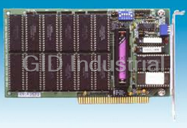
Advantech PCA-6653 Video / LCD Display Card - 16-bit ISA-bus, half-size, CHIPS 65545
Part Number
PCA-6653
Price
Request Quote
Manufacturer
ADVANTECH
Lead Time
Request Quote
Category
EMBEDDED COMPUTING » EMBEDDED COMPUTING PERIPHERALS
Specifications
BIOS
27C010, supports 4 banks, 32KB for each bank
Chipset
CHIPS 65545, integrated flat panel / CRT VGA controller
Connector
DB-44 for Flat panel Display. DB-15 for CRT. Built-in 44-pin for general purpose connector (Pin Header.) Built-in 5-pin for keyboard connection (Housing)
Display support
CRT - 1024x768 Non-interlaced analog or multisynch monitors with 256 colors. 640x480 CRT and Panel display with 64K colors. Flat panel - TFT LCD (Max resolution is 1024x768.) DSTN /STN LCD (Max resolution is 800x600.) B/W LCD. PLASMA LCD. EL
Memory
1MB DRAM on board 256Kx16 DRAM socket for frame buffer (Optional)
Power
On-board DC-DC converter supplies LCD bias voltage (VEE)
Simultaneous CRT/LCD display
Available with TFT, STN, B/W, EL, CRT
Slot
High performance 16-bit ISA-bus add-on card
Wait State
32-bit Memory read/write operation Zero wait state (when CPU write to 66545)
Windows GUI (Graphic User Interface) Accelerator
32-bit BitBLT Engine. Hardware Cursor
Features
- 132 column text mode
- 640x480 resolution in graphics modes with 32K, 64K, and 16M colors
- Resolutions up to 1024x768 in graphics modes with 256 colors
Datasheet

Extracted Text
PCA-6653
Video Display Card for
Flat Panel and CRT
Copyright Notice
This document is copyrighted by Advantech Co., Ltd. All rights
are reserved. Advantech Co., Ltd., reserves the right to make
improvements to the products described in this manual at any time
without notice.
No part of this manual may be reproduced, copied, translated, or
transmitted in any form or by any means without the prior written
permission of Advantech Co., Ltd. Information provided in this
manual is intended to be accurate and reliable. However, Advan-
tech Co., Ltd., assumes no responsibility for its use, nor for any
infringements upon the rights of third parties which may result
from its use.
All brand and product names mentioned herein are trademarks or
registered trademarks of their respective holders.
Part No. 2002665300, 1st Edition
Printed in Taiwan, September 1995
ii
Contents
Chapter 1 Introduction..................................1
Description .............................................................................. 2
Specifications .......................................................................... 3
Display Support...................................................................... 4
Video BIOS ............................................................................. 4
Simultaneous Display Mode.................................................. 5
Chapter 2 Hardware Setup ...........................7
Hardware Configuration ....................................................... 8
Connectors ............................................................................ 10
Jumper Setting ..................................................................... 11
Pin Assignments ................................................................... 12
Power Management ............................................................. 13
Chapter 3 Software Drivers and Utilities...15
Simultaneous Display Mode................................................ 16
Sleep Mode............................................................................ 16
Software Support ................................................................. 17
Driver Installation................................................................ 18
Windows Setup ............................................................................... 19
AutoCAD R12 ................................................................................. 22
Lotus 1-2-3 and Lotus Symphony ................................................. 24
VESA ............................................................................................... 26
Word ................................................................................................ 27
WordPerfect .................................................................................... 28
iii
iv
1
Introduction
Chapter 1 Introduction 1
CHAPTER
Description
The PCA-6653 is based on the CHIPS VGA flat panel/CRT controller
and is fully IBM VGA compatible. This controller offers a large set of
extended functions and higher resolutions, and it supports simulta-
neous functioning. Since the PCA-6653 VGA adapter is fully compat-
ible, you do not require any special drivers to operate in standard
modes. The enclosed software drivers allow you to take advantage of
the extended features of the PCA-6653:
High performance in Microsoft Windows
Resolutions up to 1024x768 in graphics modes with 256 colors
640x480 resolution in graphics modes with 32K, 64K, and 16M
colors
132 column text mode
Warning! Be sure to turn off the power and unplug all compo-
nents before attempting to install or adjust the PCA-
6653. Make sure the jumpers are set correctly before
connecting the PCA-6653 to your flat panel display.
Incorrect jumper settings could damage your display.
2 PCA-6653 User's Manual
Specifications
Chipset: CHIPS 65545, integrated flat panel / CRT VGA controller
Slot: High performance 16-bit ISA-bus add-on card
BIOS: 27C010, supports 4 banks, 32KB for each bank
Memory: 1MB DRAM on board
256Kx16 DRAM socket for frame buffer (Optional)
Windows GUI (Graphic User Interface) Accelerator:
32-bit BitBLT Engine
Hardware Cursor
Wait State: 32-bit Memory read/write operation
Zero wait state (when CPU write to 66545)
Simultaneous CRT/LCD display: Available with TFT, STN, B/W, EL,
CRT
Display support: CRT - 1024x768 Non-interlaced analog or multi-
synch monitors with 256 colors
640x480 CRT and Panel display with 64K colors
Flat panel - TFT LCD (Max resolution is 1024x768)
DSTN /STN LCD (Max resolution is 800x600)
B/W LCD
PLASMA LCD
EL
Connector: DB-44 for Flat panel Display
DB-15 for CRT
Built-in 44-pin for general purpose connector (Pin Header)
Built-in 5-pin for keyboard connection (Housing)
Power: On-board DC-DC converter supplies LCD bias voltage (VEE)
Power Management: Chips 65545 power saving stand-by mode
Chapter 1 Introduction 3
Driver Support
The software driver provides:
Microsoft Windows 3.XX
MS DOS
AutoCAD Release 12
Lotus 1-2-3
Lotus Symphony
VESA
Microsoft Word
WordPerfect
132 Column Text Mode (only usable in WordPerfect and Wordstar)
The PCA-6653 provides 16.7M colors with a CRT output frequency
of 65 MHz.
Video BIOS
The standard BIOS chip supports four kinds of flat panel displays:
TFT LCD: Toshiba LTM09C016
DSTN LCD: Sharp LM64183P
MONO LCD: Sharp LM64C142
EL: Planar EL640.480AD4
4 PCA-6653 User's Manual
Simultaneous Display Mode
The PCA-6653 supports simultaneous display to a CRT monitor and a
flat panel display. The flat panel may be TFT, mono, DSTN, or EL.
If you use a DSTN LCD in this mode, the display must be under 16/
256 colors or the CRT and flat panel screens will tremble. You must
add a frame buffer with 512K RAM and update the BIOS setup. Call
us for assistance.
Chapter 1 Introduction 5
6 PCA-6653 User's Manual
2
Hardware Setup
Chapter 2 Hardware Setup 7
CHAPTER
Hardware Configuration
The PCA-6653 is based on chipset 65545 and has high performance, a
simple configuration, and fully supported LCD/EL/CRT.
PCA-6653 System block diagram
Address
BIOS
Data
RGB
24
To CRT Display
H/V Sync
Address
16 24
Panel Data
Data 65540/45
To Flat Panel Display
Panel Control
+VEE
Power-on
Control
/ENVEE
Sequencing
-VEE
32
16 +V -V
512KB DC-DC
1MB Video
16-bit
Converter
Frame Buffer
Memory
ISA BUS
Figure 2-1 Block Diagram
8 PCA-6653 User's Manual
Figure 2-2 Component / Jumper Placement
Chapter 2 Hardware Setup 9
Connectors
CN1 DB-15 Female for CRT monitor
CN2 DB-44 Female for flat panel display
CN3 pin-header 44-pin for flat panel display (pin to pin
compatible with CN2)
CN4 housing 5-pin for keyboard connection
10 PCA-6653 User's Manual
Jumper Setting
Be sure the jumper setting is correct before you install the card to the
chassis. Refer to figure 2-2 for pin assignments.
JP1 2 PIN 1: standby mode to save power , 0: normal mode
JP4 2 PIN External Contrast Adjustment VR connector
JP5 3 PIN VEE for LCDs power source selection
1-2 : +VEE (output is positive)
2-3 : -VEE (output is negative)
JP6 3 PIN Panel Colock polarity select (SHFCLK)
1-2 : +SHFCLK (for LCDs)
2-3 : -SHFCLK (for EL)
JP2,JP3 2 PIN ROM BIOS Bank select
BANK JP2 JP3 LCD Model
Bank 0 1 1 LTM09C016
Bank 1 0 1 LM64C142
Bank 2 1 0 LM64183P
Bank 3 0 0 EL640.480AD4
VR1: VEE adjustment for LCD/EL
Step 1 - Short the JP4.
Step 2 - Adjust the voltage for each LCD VEE. Voltage
ranges from +12V to +40V
Note: The two jumper settings are 0 (open) and 1 (closed).
Warning! Turn off the system power, and disconnect the
cables prior to adjusting the voltage!
Adjusting the VR1 may damage the LCD/EL
display module. Call if you need assistance.
Chapter 2 Hardware Setup 11
Pin Assignments
CN1:
Pin No. Descriptions Pin No. Descriptions
1 R 9 (Not used)
2 G 10 Ground
3 B 11 (Not used)
4 (Not used) 12 (Not used)
5 Ground 13 Horizontal sync
6 Ground 14 Vertical sync
7 Ground 15 (Not used)
8 Ground
CN2 and CN3:
Pin No. Descriptions Pin No. Descriptions
1 +12V 23 P14
2 +12V 24 P15
3 Ground 25 P16
4 Ground 26 P17
5 +5V 27 P18
6 +5V 28 P19
7 VEESAFE 29 P20
8 Ground 30 P21
9 P0 31 P22
10 P1 32 P23
11 P2 33 Ground
12 P3 34 Ground
13 P4 35 ASHFCLK
14 P5 36 FLM
15 P6 37 M
16 P7 38 LP
17 P8 39 Ground
18 P9 40 ENABKL
19 P10 41 KB_DATA
20 P11 42 KB_CLK
21 P12 43 C_VR1
22 P13 44 C_VR2
12 PCA-6653 User's Manual
CN4:
Pin No. Descriptions
1 Clock
2 Data
3 (Not used)
4 Ground
5 +5V
Power Management
To save power, you can disable the Chips 65545 by setting the JP1
jumper to 1 (closed). This clears the memory and interrupts input and
output. You can use the included software if you only want to stop
output. To disable the flat panel's backlight, set CN2-pin40 (EN-
ABKL) to 0 (open).
Chapter 2 Hardware Setup 13
14 PCA-6653 User's Manual
3
Software Drivers and
Utilities
Chapter 3 Software Drivers and Utilities 15
CHAPTER
This chapter describes the installation and operation of the software
drivers on the included Display Driver diskette.
Simultaneous Display Mode
The 65545 VGA BIOS supports monochrome LCD, EL, color TFT
and STN LCD flat panel displays. It also supports interlaced and non-
interlaced analog monitors (VGA color and VGA monochrome) in
high-resolution modes while maintaining complete IBM VGA
compatibility. Digital monitors (i.e. MDA, CGA, and EGA) are NOT
supported. Multiple frequency (multisync) monitors are supported as
analog monitors.
Both CRT and panel displays can be used simultaneously. The PCA-
6653 can be set in one of three configurations: on a CRT, on a flat
panel display, or on both simultaneously. The system is initially set to
simultaneous display mode. In the utility diskette, there are three
.COM files which can be used to select the display. Simply type the
filename at the DOS prompt:
CT.COM Enables CRT display only
FP.COM Enables panel display only
SM.COM Enables both displays at the same time.
Sleep Mode
The Display Driver diskette contains two files that support sleep
mode. Simply type the filename at the DOS prompt:
ON.COM switches to normal display mode.
OFF.COM switches to sleep mode.
16 PCA-6653 User's Manual
Software Support
The drivers support the following applications using the filenames and
resolutions listed:
Application Filename Resolution Colors
Windows 3.1 LINEAR4.DRV 640x480 16
800x600 16
1024x768 16
LINEAR8.DRV 640x480 256
800x600 256
1024x768 256
LINEAR15.DRV 640x480 32K
LINEAR16.DRV 640x480 64K
LINEAR24.DRV 640x480 16M
AutoCAD R12 RCTURBOC.EXP 640x480 16
800x600 16
1024x768 16
640x480 256
800x600 256
1024x768 256
640x480 32K
640x480 64K
640x480 16M
Lotus 1-2-3 2.0 and Lotus Symphony 1.0,1.1
V132X25.DRV 132x25 (Text) 16
V132X50.DRV 132x50 (Text) 16
VESA 1.2 VESA.COM 800x600 16
1024x768 16
640x400 256
640x480 256
800x600 256
1024x768 256
640x480 32K
640x480 64K
Word 5.0 VGA600.VID 800x600 16
VGA768.VID 1024x768 16
Word 5.5 VGA55600.VID 800x600 16
VGA55768.VID 1024x768 16
Chapter 3 Software Drivers and Utilities 17
WordPerfect 5.0 CHIPS600.WPD 800x600 16
CHIPS768.WPD 1024x768 16
WordPerfect 5.1 VGA600.VRS 800x600 16
VGA768.VRS 1024x768 16
Driver Installation
Necessary prerequisites
The instructions in this manual assume that you understand elementa-
ry concepts of MS-DOS and the IBM Personal Computer. Before you
attempt to install any driver or utility you should: know how to copy
files from a floppy disk to a directory on the hard disk, understand the
MS-DOS directory structure, and know how to format a floppy disk.
If you are uncertain about any of these concepts, please refer to the
DOS or Windows user reference guides for more information before
you proceed with the installation.
Before you begin
Before you begin installing software drivers, you should make a
backup copy of the Display Driver diskette, and store the original in a
safe place. The Display Driver diskette contains drivers for several
versions of certain applications. You must install the correct version
in order for the driver to work properly so make sure you know which
version of the application you have.
18 PCA-6653 User's Manual
Windows Setup
These drivers are designed to work with Microsoft Windows 3.1. You
may install these drivers through Windows or in DOS.
Step 1: Install Windows as you normally would for a VGA display.
Run Windows to make sure that it is working correctly.
Step 2: Place the Display Driver diskette in drive A. In Windows
Program Manager, choose File from the Options Menu. Then from
the pull-down menu, choose Run . . . . At the command line prompt,
type A:\WINSETUP. Press the
Frequently asked questions
What makes Elite.Parts unique?

What kind of warranty will the PCA-6653 have?
Which carriers does Elite.Parts work with?
Will Elite.Parts sell to me even though I live outside the USA?
I have a preferred payment method. Will Elite.Parts accept it?
Why buy from GID?

Quality
We are industry veterans who take pride in our work

Protection
Avoid the dangers of risky trading in the gray market

Access
Our network of suppliers is ready and at your disposal

Savings
Maintain legacy systems to prevent costly downtime

Speed
Time is of the essence, and we are respectful of yours
Related Products

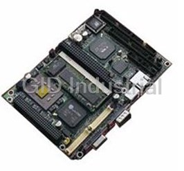
PC/104 to ISA Bus Adapter for PCM-4862
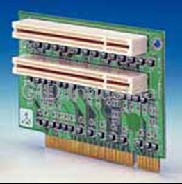
Riser card 2 x PCI for PCM-9570/9574/9576F/5864
Advantech PCM-231AV-00A1 Audio/TV-out Module | with Line-in, Line-out, Mic, Composite-video and S-Vi...
Request a Quote

The quote request has been received
Close

Facing challenges or have inquiries? Feel free to contact us!
Call Us +1-469-283-2440
What they say about us
FANTASTIC RESOURCE
One of our top priorities is maintaining our business with precision, and we are constantly looking for affiliates that can help us achieve our goal. With the aid of GID Industrial, our obsolete product management has never been more efficient. They have been a great resource to our company, and have quickly become a go-to supplier on our list!
Bucher Emhart Glass
EXCELLENT SERVICE
With our strict fundamentals and high expectations, we were surprised when we came across GID Industrial and their competitive pricing. When we approached them with our issue, they were incredibly confident in being able to provide us with a seamless solution at the best price for us. GID Industrial quickly understood our needs and provided us with excellent service, as well as fully tested product to ensure what we received would be the right fit for our company.
Fuji
HARD TO FIND A BETTER PROVIDER
Our company provides services to aid in the manufacture of technological products, such as semiconductors and flat panel displays, and often searching for distributors of obsolete product we require can waste time and money. Finding GID Industrial proved to be a great asset to our company, with cost effective solutions and superior knowledge on all of their materials, it’d be hard to find a better provider of obsolete or hard to find products.
Applied Materials
CONSISTENTLY DELIVERS QUALITY SOLUTIONS
Over the years, the equipment used in our company becomes discontinued, but they’re still of great use to us and our customers. Once these products are no longer available through the manufacturer, finding a reliable, quick supplier is a necessity, and luckily for us, GID Industrial has provided the most trustworthy, quality solutions to our obsolete component needs.
Nidec Vamco
TERRIFIC RESOURCE
This company has been a terrific help to us (I work for Trican Well Service) in sourcing the Micron Ram Memory we needed for our Siemens computers. Great service! And great pricing! I know when the product is shipping and when it will arrive, all the way through the ordering process.
Trican Well Service
GO TO SOURCE
When I can't find an obsolete part, I first call GID and they'll come up with my parts every time. Great customer service and follow up as well. Scott emails me from time to time to touch base and see if we're having trouble finding something.....which is often with our 25 yr old equipment.
ConAgra Foods