

 Manufacturers
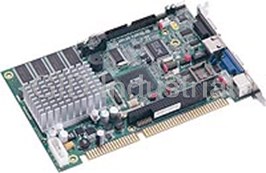
ACROSSER AR-B1675
Description
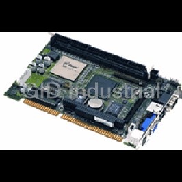
Acrosser AR-B1675 Fanless ISA-Bus Single Board Computer with VIA Mark 800MHz CPU, LCD, LAN, On-board 128MB SDRAM
Part Number
AR-B1675
Price
Request Quote
Manufacturer
ACROSSER
Lead Time
Request Quote
Category
FULL/HALF SIZE PC
Specifications
Audio
Realtek ALC655 AC'97 Stereo (MIC-In/Line-In/Line-Out)
Chipset
VT82C686B
Connector
1 x RJ45
Controller
Realtek RTL8100C (10/100Mbps)
CPU
VIA Mark 800MHz
Dimension
185mm x 122mm
Expansion
1 x PC/104 slot
GPIO
8-bit Digital I/O
Keyboard/Mouse
PS/2 Keyboard and mouse connector
Operating Temp
0~60 C (32~140 F)
Parallel Port
1 x LPT port
Power Requirement
+5V@2.5A typical, +12V@1.0A typical supports AT/ATX power function
Processor
VIA Mark
Relative Humidity
0 to 90% @ 40¢XC, non-condensing
Serial Port
2 x RS-232 (1 x DB9, 1 x onboard pin header )
Storage Temp.
-20~80 C (-4~176 C F)
USB Port
4 x USB1.1 (4 x onboard pin header)
Features
- 2x COM, 4 x USB1.1, VGA, 18-bit LVDS, 1 x 10/100 LAN
- Fanless design
- Onboard 128MB SDRAM
- Onboard VIA mark 800MHz
- PC/104 interface
Datasheet

Extracted Text
AR-B1675 User’s Guide
AR-B1675
VIA Mark CoreFusion 800MHz, Half Size ,On Board
SDRAM,VGA,LVDS with One SDRAM SO-DIMM, built in
LAN,CF Type-II
Edition: 2.0
Book Number: AR-B1675-06.11.17
AR-B1675
1
AR-B1675 User’s Guide
@Copyright 2005
All Rights Reserved.
Manual first edition Apr 11, 2006
The information in this document is subject to change without prior
notice in order to improve reliability, design and function and does not
represent a commitment on the part of the manufacturer.
In no event will the manufacturer be liable for direct, indirect, special,
incidental, or consequential damages arising out of the use or inability to
use the product or documentation, even if advised of the possibility of
such damages.
This document contains proprietary information protected by copyright.
All rights are reserved. No part of this manual may be reproduced by
any mechanical, electronic, or other means in any form without prior
written permission of the manufacturer.
Trademarks
AR-B1675 is registered trademarks X-Fire Acrosser, IBM PC is a
registered trademark of International Business Machines Corporation.
Pentium is a registered trademark of Intel Technologies, Inc. Award is
registered trademarks of Award Software International, Inc. Other
product names mentioned herein are used for identification purposes
only and may be trademarks and/or registered trademarks of their
respective companies.
AR-B1675
2
AR-B1675 User’s Guide
Contents
Contents ................................................................ 3
Introduction............................................................. 5
1.1 Specifications:........................................................................... 5
1.2 What You Have......................................................................... 6
Installation .............................................................. 7
2.1 AR-B1675’s Layout................................................................... 7
2.2 Power Button Setting ................................................................ 9
2.3 CMOS Reset........................................................................... 10
2.4 Jumper description ................................................................. 10
Connection............................................................ 12
3.1 Ultra ATA33 IDE Disk Drive Connector(IDE2)........................ 12
3.2 Serial Ports(COM2) ................................................................ 13
3.3 Keyboard / Mouse Connector(MS_KB1,2) ............................. 13
3.4 USB Port Connector(USB1~4) ............................................... 14
3.5 Fan Connector (FAN1) ........................................................... 14
3.6 LAN RJ45 Connector (J4)....................................................... 15
3.7 Compact Flash Storage Card Socket(CF1)............................ 15
3.8 VGA Connector(VGA1)........................................................... 16
AR-B1675
3
AR-B1675 User’s Guide
3.9 AUDIO Connector(AUDIO1)................................................... 17
3.10 SDRAM SODIMM Socket (DIMM1)...................................... 17
3.11 8-BIT GPIO Connector(CN1)................................................ 17
3.12 Parallel port(LPT1)................................................................ 18
3.13 LVDS Connector(LVDS1)..................................................... 18
Award BIOS Setup................................................ 20
4.1 Introduction ............................................................................. 20
4.2 Starting Setup ......................................................................... 20
4.3 Using Setup ............................................................................ 21
4.4 Main Menu .............................................................................. 22
4.5 Advanced BIOS Features ....................................................... 25
4.6 PnP/PCI Configuration Setup ................................................. 27
4.7 Peripheral................................................................................ 28
4.8 H/W Monitor............................................................................ 29
4.9 Boot……………...…………………………………………………30
4.10 Exit Selecting…………………………………………………….31
AR-B1675
4
AR-B1675 User’s Guide
1
Introduction
1.1 Specifications:
CPU : Onboard VIA Mark CoreFusion 800MHz CPU.
Chipset : VIA VT82C686B South Bridge
RAM memory : Onboard 128M SDRAM and One SDRAM SO-DIMM Socket
support to 1 GB/133MHz.
Display Controller: MARK integrated ProSavage 4 3D/2D Graphic Controller.
Ultra DMA 133 IDE Interface : One PCI Enhance IDE channel.
TM TM
CompactFlash interface : Supports CompactFlash Type II socket for
Compact Flash Disk or IBM Micro Drive.
Series ports : Two high-speed 16C550 compatible UARTs ports.COM2 can
also support RS-422/485.
Parallel Port: IEEE-1284 compliant. Supports SPP/EPP/ECP mode.
USB port : Support Four USB 2.0 compatible ports.
Audio Connector: supports Line-in, Line-out, MIC-in.
Digital IO: Supports four digital-in, and four digital-out TTL-level I/O ports.
PS/2 Mouse/Keyboard Connector
Watchdog timer : Time setting form 1 to 4096 second / minute System Reset
generate when CPU did not periodically trigger the timer.
Intel LAN Controller: 1 ports IEEE 802.3u Auto-Negotiation support for
Realtek RTL8100C 10/100BASE-TX Connected to your LAN through RJ45
connector.
Power Consumption : 5V / 2.75A
AR-B1675
5
AR-B1675 User’s Guide
Operating Temperature : 0 ~ 60 C
° °
Dimension: 122mm(W) X 185mm(L)
1.2 What You Have
In addition to this User's Manual, the AR-B1675 package includes the
following items:
AR-B1675 board
Setting Manual
Software utility CD
Serial port wired cable
Audio wired cable
PS/2 Mouse& Keyboard interface Y-cable
Hard disk drive adapter cable
USB port on one bracket cable
Parallel port cable
AR-B1675
6
AR-B1675 User’s Guide
2
Installation
This chapter describes how to install the AR-B1675. At first, the
layout of AR-B1675 is shown, and the unpacking information that you
should be careful is described. The jumpers and switches setting for
the AR-B1675’s configuration
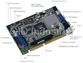
2.1 AR-B1675’s Layout
Top Placement
AR-B1675
7
AR-B1675 User’s Guide
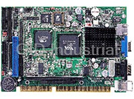
Bottom Placement
AR-B1675
8
AR-B1675 User’s Guide
2.2 Power Button Setting
CN3 : Power Connector
•
PIN DESCRIPTION
1 12V
2 GND
3 GND
4 5V
PWRON1 : Power Button Connector
•
Pin DESCRIPTION
Open Showdown
Short Power ON
HDLED1 : HardDisk LED Connector
•
Pin DESCRIPTION
1 +5V
2 HD_LED
RST1 : Reset Button Connector
•
Pin DESCRIPTION
Open Normal
Short Reset System
CN2 : Power ON Pin Header
•
Pin DESCRIPTION
1 5VSB
2 GND
3 PS_ON
AR-B1675
9
AR-B1675 User’s Guide
2.3 CMOS Reset
CMOS1 : CMOS pin header
•
CMOS1 DESCRIPTION
1-2 Normal Operation
2-3 Reset CMOS
2.4 Jumper description
JP2 : Select CF Master or Slave mode
•
JP2 DESCRIPTION
Short Master
Open Slave
• JP3 : COM1/2 Select RI is 12V/5V or signal
PIN DESCRIPTION PIN DESCRIPTION
1 12V 2 12V
3 COM_RI1 4 COM_RI2
5 5V 6 5V
7 COM_RI1 8 COM_RI2
9 NRI1 10 NRI2
J2 : Select COM2 is RS232 or RS422/485
•
J2 DESCRIPTION
1-2 RS232
3-4 RS422
5-6 RS485
AR-B1675
10
AR-B1675 User’s Guide
JP1: Select LCD Voltage
•
JP1 DESCRIPTION
1-2 +3.3V
2-3 +5V
J1 : Inverter Power Connector
•
PIN NO. DESCRIPTION
1 +12V
2 +12V
3 GND
4 BKLTEN
5 GND
6 BKLTCTL
Kb_key1: Keyboard Lock Connector
•
JP1 DESCRIPTION
Short Normal
Open Lock
Ms_key1: Mouse Lock Connector
•
JP1 DESCRIPTION
Short Normal
Open Lock
AR-B1675
11
AR-B1675 User’s Guide
3
Connection
This chapter describes how to connect peripherals, switches and
indicators to the AR-B1675 board.
3.1 Ultra ATA33 IDE Disk Drive Connector(IDE2)
You can attach two IDE( Integrated Device Electronics) hard disk drives
to the AR-B1675 IDE controller.
IDE 2 : Secondary IDE Connector (44 Pins)
PIN DESCRIPTION PIN DESCRIPTION
1 RESET# 2 GROUND
3 DATA 7 4 DATA 8
5 DATA 6 6 DATA 9
7 DATA 5 8 DATA 10
9 DATA 4 10 DATA 11
11 DATA 3 12 DATA 12
13 DATA 2 14 DATA 13
15 DATA 1 16 DATA 14
17 DATA 0 18 DATA 15
19 GROUND 20 N/C
21 N/C 22 GROUND
23 IOW# 24 GROUND
25 IOR# 26 GROUND
27 N/C 28 BALE
29 N/C 30 GROUND
31 INTERRUPT 32 IOCS16#
33 SA1 34 N/C
35 SA0 36 SA2
37 HDC CS0# 38 HDC CS1#
39 HDD ACTIVE# 40 GROUND
41 +5V LOGIC 42 +5V MOTOR
43 GROUND 44 TYPE
AR-B1675
12
AR-B1675 User’s Guide
3.2 Serial Ports(COM2)
The AR-B1675 offers two high speeds NS16C550 compatible UARTs
with Read/Receive 16 byte FIFO serial ports.
• COM1 : RS-232 Serial port
PIN DESCRIPTION PIN DESCRIPTION
1 NDCD 2 NRX
3 NTX 4 NDTR
5 GND 6 NDSR
7 NRTS 8 NCTS
9 NRIA_12V 10 NC
COM2: RS-232 with RS-422/485 Serial port(Pin Header)
•
PIN DESCRIPTION PIN DESCRIPTION
1 NDCD 2 NDSR
3 NSIN 4 NRTS
5 NRIB 6 NCTS
7 NSOUT 8 NRI
9 GND 10 GND
11 TX+ 12 TX-
13 RX+ 14 RX-
3.3 Keyboard / Mouse Connector(MS_KB1,KB_MS2)
A PS/2 type connector(MS_KB1)is for easy connection to a keyboard
and PS/2 mouse. The board comes with a Y split PS/2 cable for
keyboard and mouse connection.
MS_KB1 : Keyboard Mouse PS2 Port
•
PIN DESCRIPTION PIN DESCRIPTION
1 KB_DAT 2 MS_DAT
3 GND 4 +5V
5 KB_CLK 6 MS_CLK
7 GND 8 GND
AR-B1675
13
AR-B1675 User’s Guide
KB_MS1 : Keyboard Mouse JST Port
•
PIN NO. DESCRIPTION
1 +12V
2 +12V
3 GND
4 BKLTEN
5 GND
6 BKLTCTL
3.4 USB Port Connector(USB1~4)
The AR-B1675 provides four USB port, four pin header .
• USB1/2/3/4: USB Connector(Pin header)
PIN DESCRIPTION PIN DESCRIPTION
1 2
VCC GND
3 4
USB- USB+
5 6
USB+ USB-
7 8
GND VCC
3.5 Fan Connector (FAN1)
The AR-B1675 provides one connectors for CPU cooling fan.
FAN1: Fan Connector for CPU
•
PIN NO. DESCRIPTION
1 FANSP1
2 +5V
3 GNDl
AR-B1675
14
AR-B1675 User’s Guide
3.6 LAN RJ45 Connector (J4)
AR-B1675 is equipped with built-in 10/100Mbps Ethernet Controller. You
can connect it to your LAN through RJ45 LAN connector. The pin
assignments are as following:
• LAN1 : LAN RJ45 Connector
PIN NO. DESCRIPTION PIN NO. DESCRIPTION
1 TX+ 5. N/C
2 TX- 6. RX-
3. RX+ 7. N/C
4. N/C 8. N/C
81
3.7 Compact Flash Storage Card Socket(CF1)
The AR-B1675 configures Compact Flash Storage Card in IDE Mode.
This type II Socket is compatible with IBM Micro Drive.
CF1 : Compact Flash Storage Card Socket pin assignment
•
PIN DESCRIPTION PIN DESCRIPTION
1 GROUND 26 CARD DETECT1
2 D3 27 D11
3 D4 28 D12
4 D5 29 D13
5 D6 30 D14
6 D7 31 D15
7 CS1# 32 CS3#
AR-B1675
15
AR-B1675 User’s Guide
8 N/C 33 N/C
9 GROUND 34 IOR#
10 N/C 35 IOW#
11 N/C 36 PULL HIGH
12 N/C 37 IRQ15
13 VCC 38 VCC
14 N/C 39 MASTER/SLAVE
15 N/C 40 N/C
16 N/C 41 RESET#
17 N/C 42 IORDY
18 A2 43 N/C
19 A1 44 PULL HIGH
20 A0 45 ACTIVE#
21 D0 46 PDIAG#
22 D1 47 D8
23 D2 48 D9
24 N/C 49 D10
25 CARD DETECT2 50 GROUND
Note: If IDE2 & CFD1 both in used, CFD1 must be as “Master” & IDE2 is as “Slave”.
3.8 VGA Connector(VGA1)
The AR-B1675 has a built-in 15-pin VGA connector accepting the CRT
monitor
VGA1 : 15-pin D-Sub Connector
•
PIN DESCRIPTION PIN DESCRIPTION
1 L_RED 2 L_GREEN
3 L_BLUE 4 MON2PU
5 GND 6 GND
7 GND 8 GND
9 +5V 10 GND
11 MONOPU 12 5VDDCDA
13 HSYNC 14 VSYNC
15 5VDDCCL
AR-B1675
16
AR-B1675 User’s Guide
3.9 AUDIO Connector(AUDIO1)
AUDIO1 : Audio Pin Header
•
PIN DESCRIPTION PIN DESCRIPTION
1 LINE OUT R 2 LINE OUT L
3 GND 4 GND
5 LINE IN R 6 LINE IN L
7 MIC IN 8 GND
9 GND 10 GND
3.10 SDRAM SODIMM Socket (DIMM1)
There are one 144-pin SDRAM DIMM slots to accept 3.3V. The max Memory
size is 1GB.
• DIMM1
3.11 8-BIT GPIO Connector(CN1)
• CN1: 4 BIT Input/Output GPIO Connector
PIN DESCRIPTION PIN DESCRIPTION
1 GND 2 +5V
3 DIOI0 4 DIOO0
5 DIOI1 6 DIOO1
7 DIOI2 8 DIOO2
9 DIOI3 10 DIOO3
AR-B1675
17
AR-B1675 User’s Guide
3.12 Parallel port(LPT1)
This port is usually connected to a printer. The AR-B1675 cludes an on-board
parallel port.
• LPT1: Parallel Port Connector
PIN DESCRIPTION PIN DESCRIPTION
1 STB- 14 AFD-
2 PD0 15 ERR-
3 PD1 16 INIT-
4 PD2 17 SLIN-
5 PD3 18 GND
6 PD4 19 GND
7 PD5 20 GND
8 PD6 21 GND
9 PD7 22 GND
10 ACK- 23 GND
11 BUSY 24 GND
12 PE 25 GND
13 SLCT 26 X
3.13 LVDS Connector(LVDS1)
• LVDS1 : LVDS Interface Connector
AR-B1675
18
AR-B1675 User’s Guide
PIN DESCRIPTION PIN DESCRIPTION
1 LCDVDD 2 GND
3 TRXEC- 4 TRXEC+
5 GND 6 TRXE2-
7 TRXE2+ 8 GND
9 TRXE1- 10 TRXE1+
11 NC 12 NC
13 TRXE0+ 14 TRXE0-
15 GND 16 TRXOC+
17 TRXOC- 18 GND
19 TRXO2+ 20 TRXO2-
21 NC 22 TRXO1+
23 TRXO1- 24 NC
25 TRXO0+ 26 TRXO0-
27 NC 28 NC
29 LCDVDD 30 LCDVDD
AR-B1675
19
AR-B1675 User’s Guide
4
Award BIOS Setup
4.1 Introduction
This chapter discusses the Setup program built into the BIOS. The
Setup program allows users to configure the system. This configuration
is then stored in battery-backed CMOS RAM so that it retains the Setup
information while the power is off.
4.2 Starting Setup
The BIOS is immediately active when you turn on the computer. While
the BIOS is in control, the Setup program can be activated in one of two
ways:
1. By pressing immediately after switching the system on, or
2. By pressing the key when the following message appears
briefly at the bottom of the screen during the POST (Power On Self-
Test).
Press DEL to enter SETUP.
If the message disappears before you respond and you still wish to enter
Setup, restart the system to try again by turning it OFF then ON or
pressing the "RESET" button on the system case. You may also restart
by simultaneously pressing
Frequently asked questions
What makes Elite.Parts unique?

What kind of warranty will the AR-B1675 have?
Which carriers does Elite.Parts work with?
Will Elite.Parts sell to me even though I live outside the USA?
I have a preferred payment method. Will Elite.Parts accept it?
Why buy from GID?

Quality
We are industry veterans who take pride in our work

Protection
Avoid the dangers of risky trading in the gray market

Access
Our network of suppliers is ready and at your disposal

Savings
Maintain legacy systems to prevent costly downtime

Speed
Time is of the essence, and we are respectful of yours
Related Products
Request a Quote

The quote request has been received
Close

Facing challenges or have inquiries? Feel free to contact us!
Call Us +1-469-283-2440
What they say about us
FANTASTIC RESOURCE
One of our top priorities is maintaining our business with precision, and we are constantly looking for affiliates that can help us achieve our goal. With the aid of GID Industrial, our obsolete product management has never been more efficient. They have been a great resource to our company, and have quickly become a go-to supplier on our list!
Bucher Emhart Glass
EXCELLENT SERVICE
With our strict fundamentals and high expectations, we were surprised when we came across GID Industrial and their competitive pricing. When we approached them with our issue, they were incredibly confident in being able to provide us with a seamless solution at the best price for us. GID Industrial quickly understood our needs and provided us with excellent service, as well as fully tested product to ensure what we received would be the right fit for our company.
Fuji
HARD TO FIND A BETTER PROVIDER
Our company provides services to aid in the manufacture of technological products, such as semiconductors and flat panel displays, and often searching for distributors of obsolete product we require can waste time and money. Finding GID Industrial proved to be a great asset to our company, with cost effective solutions and superior knowledge on all of their materials, it’d be hard to find a better provider of obsolete or hard to find products.
Applied Materials
CONSISTENTLY DELIVERS QUALITY SOLUTIONS
Over the years, the equipment used in our company becomes discontinued, but they’re still of great use to us and our customers. Once these products are no longer available through the manufacturer, finding a reliable, quick supplier is a necessity, and luckily for us, GID Industrial has provided the most trustworthy, quality solutions to our obsolete component needs.
Nidec Vamco
TERRIFIC RESOURCE
This company has been a terrific help to us (I work for Trican Well Service) in sourcing the Micron Ram Memory we needed for our Siemens computers. Great service! And great pricing! I know when the product is shipping and when it will arrive, all the way through the ordering process.
Trican Well Service
GO TO SOURCE
When I can't find an obsolete part, I first call GID and they'll come up with my parts every time. Great customer service and follow up as well. Scott emails me from time to time to touch base and see if we're having trouble finding something.....which is often with our 25 yr old equipment.
ConAgra Foods