ACROMAG 800C-SIP
Datasheet
Extracted Text
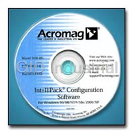
® IntelliPack 800 Series ■Special Features Transmitters .................(Page 50) Signal Conditioning IntelliPack transmitter units convert sensor inputs ■Universal I/O ranges cover a wide range of to isolated process current or voltage output sig- applications to reduce stock inventories. nals. Each unit accepts a variety of input and ■Windows 95/98/NT software configuration output ranges to support a broad range of appli- simplifies IntelliPack module setup. cations. An optional relay output enables local alarms. Plus, the internal microcontroller can ■Push button field calibration makes perform many signal processing and transfer routine maintenance easy without a PC. functions. ■Internal microcontroller provides intelligent signal processing capabilities. Input ■Thermocouple/RTD/ohms/DC millivolts ■Quick-disconnect terminals facilitate installa- ■DC voltage/current tion and removal of I/O modules. ■Frequency/pulse counter ■Field diagnostics enhanced with software■AC current ® IntelliPack minimize downtime. Output Intelligent ■Universal DC voltage/current IntelliPack Transmitter Transmitters,■SPDT relay Alarms, and Programmable Programmable Functions Input Output Math Modules All functions are standard ■Signal linearizer Programmable Relay The IntelliPack series is a high-performance line Function Output■Square root computation of multi-function I/O modules. IntelliPack units ■Signal average computation feature universal input/output ranges and an Software DC■Pulse counting Configuration Power intelligent microcontroller to provide extreme Port■Limit alarm flexibility and powerful signal conditioning capabilities. Alarms . . . . . . . . . . . . . . . . . .(Page 64) Since each IntelliPack module supports many I/O IntelliPack IntelliPack alarm units monitor sensor inputs and Alarm configurations, you can handle a broad range of provide relay actuation if conditions exceed user- applications with only a few models. Now you defined limits. An internal microcontroller pro- Programmable Relay can reduce your spare inventory stock and still Inputs Outputs vides signal processing and logic functions, nor- remain covered in an emergency. mally found only in expensive controllers, for a ® ® Programmable variety of intelligent alarm functions. Dual relay Windows 95/98/NT software helps you quickly Alarm Functions units support two different alarm functions at the configure IntelliPacks for your application. With same time. just a few mouse clicks, you can select your Software DC Configuration Power desired input/output ranges and other operating Port Inputs parameters from a list of available options. And ■Thermocouple/RTD/ohms/DC millivolts if your operating requirements change, a simple ■DC voltage/current reconfiguration lets you adapt in a hurry with IntelliPack■AC current minimal downtime. Math/Computation Module Once configured, IntelliPacks are very easy to Outputs Programmable Programmable adjust in the field with standard calibrators (no■One DPDT relay or two SPDT relays Inputs Outputs PC required). Front panel push buttons simplify Functions changes to setpoints, deadbands, and zero/full- Programmable Relay Math/Computation Output All functions are standard on every alarm unit. scale values. LEDs clearly indicate the status and ■Limit and window (band-pass) alarm mode of operation. Software DC■Deviation alarm Configuration Power ■Rate-of-change alarm Port ■On/off controller ■Peak/valley signal detection Tel: 248-624-1541 Fax: 248-624-9234 e-mail: sales@acromag.com www.acromag.com 46 ® IntelliPack ® IntelliPack Signal Conditioners Input and Output Ranges Math Modules .........(Page 76)■Fast Installation ■Universal DC voltage/current IntelliPack math modules perform a variety of Step 1 Run configuration software offline to ■Frequency, pulse, PWM outputs complex mathematical computations on up to select desired operating parameters. four input signals and provide a DC or frequency Functions Step 2 Print configuration or save to disk. output signal that represents the calculated result. ■Add, subtract, multiply, divide Typical applications include calculating sums, Step 3 Connect PC to IntelliPack and ■Square root, exponential, logarithmic deltas, averages, flow rates, volumes, and tracking download configuration data. ■Absolute value, minimum/maximum minimum/maximum values. Equations are entered ■High/low selector, track and hold Step 4 Disconnect PC and install using a freeform format, the same as in most ■Trigonometric (sine, cosine, tangent) IntelliPack module in the field. popular spreadsheet programs. ■Conditional arguments (if, then, and, or) Step 5 Optional. Calibrate in field using push- buttons on front panel. Configuration Diagram ■Easy Software + PC running POWER Acromag 10 TO 36VDC Configuration Win 95-XP/NT/2000 Configuration Software Model 5030-881 Acromag’s configuration software is the key to IntelliPack Module the IntelliPack’s easy-to-use operation. The soft- RUN ST ware employs the friendly Windows 95/98/NT RLY 1 2 interface with pull-down selection menus and MODE RJ11 Jack SET (6 Conductor) fill-in-the-blank fields to speed you through a RST 1 RJ11 Plug RJ11 Plug few brief configuration screens. No programming (6 Conductor) RST 2 Configuration Port: (6 Conductor) 6 Foot Cable Allows full is required. configuration of Model 5030-902 IntelliPack module Interface Cable Model 5030-913 An adapter plugs into the serial port of your (adapter to IntelliPack) Serial Port Adapter computer. It serves as an isolated interface After the initial software configuration, a PC is no longer required. Field calibration is easily handled with the between the IntelliPack and the PC. A cable IntelliPack’s push-buttons, status LEDs and a standard field calibrator. with RJ11 phone-style plugs at each end links the adapter to the IntelliPack’s serial port. The software, adapter, and cable are sold as a kit (Model 800C-SIP) for easy ordering. Once connected, the software reads the IntelliPack’s non-volatile memory to determine the unit type and loads the appropriate configu- ration form with several property pages. As you select the input range and alarm function on the general property page, the other pages are dynamically customized to speed you through the procedure. After you select the operating parameters, the configuration is downloaded and stored in the IntelliPack’s memory. The con- figuration is also saved to a file for subsequent downloading to other modules or for quick modifications. This capability saves you valuable downtime and archives your settings. After you complete the configuration, the soft- ware provides a detailed printout to document your application. Typical software configuration screen. Data is uploaded from the IntelliPack module. Tel: 248-624-1541 Fax: 248-624-9234 e-mail: sales@acromag.com www.acromag.com 47 ® IntelliPack 800 Series ■Software Diagnostics The configuration software also shows you the current status of your IntelliPack module. A test screen (shown at right) indicates the current input signal value and the averaged value. The status of the relay and output signal are also dis- played. You can override the output for 10 seconds to verify the system is responding properly. The screen’s IntelliPack diagram has representative LEDs to help you detect any bulb failures and verify proper operation. On alarm modules, you can reset latched relays in software by clicking the screen’s reset button with your mouse. Quickly test or monitor your IntelliPack module with a software screen that displays all current values. ■Software Calibration The IntelliPack’s configuration software makes calibrating your transmitters and alarms very easy. You can upload your IntelliPack’s current calibration and quickly verify the settings or make changes on the input, output and thermo- couple reference junction calibration property sheets. The output calibration window has a slider con- trol that you can drag with your mouse. This slid- er allows you to adjust the output current or voltage signal independent of the input signal. If a unit is miscalibrated or you make a mistake, you can instantly restore the factory calibration settings. The original values are displayed on the screen. Easily set calibration values by simply typing in the values or restore original factory settings instantly. Tel: 248-624-1541 Fax: 248-624-9234 e-mail: sales@acromag.com www.acromag.com 48 ® IntelliPack ® IntelliPack Signal Conditioners The following tables describe push-button and■Simple Push-Button LED functions for alarm and transmitter module Field Configuration types. After the initial software configuration, key functions may be reprogrammed in the field Push-Buttons (Alarms) Mode: Push to enter field configuration mode. without a PC. Push-buttons let you adjust the Acromag Acromag RUN RUN Set: Accepts input data during field calibration. IntelliPack’s setpoint, deadband, zero, and full ST ST scale signal values with conventional field RST 1: Resets a latched alarm for relay 1. calibrators. LEDs indicate the mode and guide RLY RST 2: Resets a latched alarm for relay 2. Z/FS 12 you through a few short steps. Latched relays Push-Buttons (Transmitters) RELAY may also be reset in the field. Mode: Push to enter field configuration mode. MODE MODE Set: Accepts input data during field calibration. With IntelliPacks, zero and span adjust- ▲: Calibrates (increases) the output signal. ments are one-step operations. Unlike SET many potentiometer-based instruments,▼: Calibrates (decreases) the output signal. IntelliPack zero/span adjustments are independ- LED Indicators (Alarms) RST 1 ent and non-interactive. The internal micro- Run (Green) - Indicates power applied. processor holds the zero setting constant while Flashes when performing diagnostics. the span is adjusted for precise calibration in a RST 2 ST (Yellow) - Status LED flashes to indicate input is out SET of range or a sensor break has been detected. single iteration. Relay 1 Alarm (Yellow) - Constant ON indicates alarm condition for relay 1. Relay 2 Alarm (Yellow) - Constant ON indicates alarm condition for relay 2. R R LED Indicators (Transmitters) Run (Green) - Indicates power applied. Flashes when performing diagnostics. ST (Yellow) - Status LED flashes to indicate input is out of range or a sensor break has been detected. Z/FS (Yellow) - Lights or flashes to indicate the input zero or full-scale value is being calibrated. Transmitter Alarm RLY (Yellow) - Lights to indicate alarm condition or relay setpoint adjustments are being made. Flashes for deadband adjustments. Tel: 248-624-1541 Fax: 248-624-9234 e-mail: sales@acromag.com www.acromag.com 49
Frequently asked questions
What makes Elite.Parts unique?

What kind of warranty will the 800C-SIP have?

Which carriers does Elite.Parts work with?

Will Elite.Parts sell to me even though I live outside the USA?

I have a preferred payment method. Will Elite.Parts accept it?


 Manufacturers


What they say about us
FANTASTIC RESOURCE
One of our top priorities is maintaining our business with precision, and we are constantly looking for affiliates that can help us achieve our goal. With the aid of GID Industrial, our obsolete product management has never been more efficient. They have been a great resource to our company, and have quickly become a go-to supplier on our list!
Bucher Emhart Glass
EXCELLENT SERVICE
With our strict fundamentals and high expectations, we were surprised when we came across GID Industrial and their competitive pricing. When we approached them with our issue, they were incredibly confident in being able to provide us with a seamless solution at the best price for us. GID Industrial quickly understood our needs and provided us with excellent service, as well as fully tested product to ensure what we received would be the right fit for our company.
Fuji
HARD TO FIND A BETTER PROVIDER
Our company provides services to aid in the manufacture of technological products, such as semiconductors and flat panel displays, and often searching for distributors of obsolete product we require can waste time and money. Finding GID Industrial proved to be a great asset to our company, with cost effective solutions and superior knowledge on all of their materials, it’d be hard to find a better provider of obsolete or hard to find products.
Applied Materials
CONSISTENTLY DELIVERS QUALITY SOLUTIONS
Over the years, the equipment used in our company becomes discontinued, but they’re still of great use to us and our customers. Once these products are no longer available through the manufacturer, finding a reliable, quick supplier is a necessity, and luckily for us, GID Industrial has provided the most trustworthy, quality solutions to our obsolete component needs.
Nidec Vamco
TERRIFIC RESOURCE
This company has been a terrific help to us (I work for Trican Well Service) in sourcing the Micron Ram Memory we needed for our Siemens computers. Great service! And great pricing! I know when the product is shipping and when it will arrive, all the way through the ordering process.
Trican Well Service
GO TO SOURCE
When I can't find an obsolete part, I first call GID and they'll come up with my parts every time. Great customer service and follow up as well. Scott emails me from time to time to touch base and see if we're having trouble finding something.....which is often with our 25 yr old equipment.
ConAgra Foods