

 Manufacturers
ACROMAG 150T-RBC-P002-X-20
Description
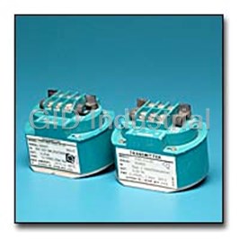
Acromag 150T-RBC-P002-X-20 Transmitter. 1500 Series | 150T Series
Part Number
150T-RBC-P002-X-20
Price
Request Quote
Manufacturer
ACROMAG
Lead Time
Request Quote
Category
PROCESS INSTRUMENT
Datasheet

Extracted Text
1500 Series 150T Loop-Powered Transmitter Transmitters 150T PLC / DCS + + 4-20mA Sensor IN OUT – – 24V DC Rs ■Description■Special Features These loop-powered transmitters convert low■Excellent accuracy and stability ensure reliable level sensor inputs to proportional process cur- measurements in harsh industrial environments. rent output signals. The output and power share ■RFI and EMI resistance minimize the effects the same pair of wires. 150T Series of noise. Units are not isolated. Input sensor must be isolat- ■Wide range zero and span adjustment enable ed from ground if the output circuit is grounded. precise calibration. RTD Input These two-wire transmitters deliver outstanding ■RTD signal linearization improves accuracy and performance and a broad range of flexibility for Input Ranges reduces drift. remote or control room mounting. They feature ■100 ohm Platinum (385/392) RTD rugged construction and remain stable even in■RTD break detection indicates open RTD fail- (2, 3, or 4-wire connection) harsh industrial environments. ures with field-selectable upscale/downscale ■10 ohm Copper RTD (2 or 3-wire) operation (downscale only for differential RTD input). ■Differential RTD (two 100 ohm Pt-385/392 RTDs, 4-wire) ■RTD lead wire compensation eliminates the effect of the wire’s resistance. Output Range 4 to 20mA DC Power requirement 150T Dimensions 12 to 50V DC, loop-powered Approvals CSA and FM Intrinsically Safe Class I; Division 1; Groups A, B, C, D Hazardous Location Class I; Division 2; Groups A, B, C, D Dimensions are in inches (millimeters). Tel: 248-624-1541 Fax: 248-624-9234 e-mail: sales@acromag.com www.acromag.com 154 1500 Series 1500 Series Isolated Transmitters ■Output■Environmental Single RTD Input Output Range Ambient Temperature Range Models 4-20mA DC output. -15 to 185°F (-25 to 85°C) The following specifications are for single RTD input Output Limits (approximate) Ambient Temperature Effect (Combined models. Specifications for differential input models 3.8mA DC to 30mA DC effects of zero and span over temperature) are listed on the next page. -RBP: Less than ±0.01% of output span per °F Output Ripple (±0.018% per °C) over ambient temperature range for Less than ±0.05% of maximum output span. reference test conditions.■Performance Current Drive Capability -RBC: Less than ±0.025% of output span per °F Reference Test Conditions RLOAD (max.) = (VSUPPLY -12V)/20mA. (±0.045% per °C) over ambient temperature range for -RBP: At VSUPPLY = 24V, RLOAD = 0 to 600 ohms reference test conditions. Input: 100 ohm, 3-wire Platinum, 0-100°C, (Alpha = 0.00385); Load Resistance Effect Isolation Output: 4-20mA into 500 ohm load; +25nA, typical. Less than ±0.005% of output span No input circuit isolation, input sensor must be isolat- for 100 ohm change. ed from ground if the output circuit is grounded. -RBC: Input: 10 ohm, 3-wire Copper (9.035 ohms at 0°C), Accuracy EMI Resistance 0 to 100°C; Includes combined effects of transmitter repeatability, Less than ±0.25% of output span effect with switch- Output: 4-20mA into 500 ohm load hysteresis, terminal point linearity and adjustment res- ing solenoids or commutator motors. Ambient temperature: 77°F (25°C) olution. Does not include sensor error. Noise Rejection: Power supply: 24V DC supply. -RBP: ±0.1% of calibrated span or ±0.1°C whichever Common Mode: Not applicable; non-isolated. is greater for spans up to 720°F (400°C); ±0.25% of Normal Mode: 26dB at 60 Hz, 100 ohm source; 20dB ■Input calibrated span for spans greater than 720°F (400°C). at 60 Hz, 10 ohm source. Input range -RBC: ±0.25% of calibrated span or ±0.25°C RFI Resistance -RBP: 100 ohm Platinum Resistance Temperature whichever is greater. Less than ±0.5% of output span with RFI field Sensor (RTD), 2, 3, or 4 wire connection. Standard Response Time strengths up to 10V/meter at frequencies of 27, 151 calibration is based on the international R vs. T curve For a step input the output reaches 98% of output and 467 MHz. having an alpha of 0.00385 ohms/ohm/°C (Pt-385). span in 350ms, typical. Unit can also be calibrated for sensors having an alpha Surge Withstand Capability (SWC) of 0.003925 ohms/ohm/°C (Pt-392). Excitation current Bandwidth Input/Output terminations rated per ANSI/IEEE C37.90- is 1.0mA DC. The span and zero adjustment is a func- -3dB at 3 Hz, typical 1978. Unit is tested to a standardized test waveform tion of the RTD range code. Note: Linearization is that is representative of surges (high frequency transient maintained for any calibration within defined range.■Power electrical interference), observed in actual installations. -RBC: 10 ohm Copper Resistance Temperature Sensor Power Supply Approvals (CSA, FM) (RTD), 2 or 3 wire connection. Standard calibration is External loop power supply required, minimum 12V Intrinsically Safe based on a Copper RTD, 9.035 ohms at 0°C. DC, maximum 50V DC. Unit has reverse polarity Class I; Division 1; Groups A, B, C, D. Maximum excitation is 2.0mA DC. The span and zero protection. adjustment range is a function of the RTD range code. Hazardous Location Power Supply Effect Note: Copper sensor is linear between -50°C and Class I; Division 2; Groups A, B, C, D. DC Volts: ±0.001% of output span per volt DC. 150°C per manufacturers tables. 60/120 Hz ripple: ±0.01% of span per volt peak to■Physical Linearization peak of power supply ripple. Case The unit linearizes the RTD signal to provide an output Self-extinguishing polypropylene UL94 V-O, recognized signal that represents the percent of span value of the by CSA, color blue. measured temperature. Printed Circuit Boards RTD Break Detection Military grade FR-4 epoxy glass circuit board. Standard units shipped with upscale detection; jumper J1 out. If unit is ordered with downscale detection, J1 Connections will be installed. Barrier-type terminal strip using No. 6 screw & clamp plates. Wire range 12-26 AWG. Lead Wire Compensation -RBP: Zero shift is less than 0.01% per ohm of lead Environmental Protection resistance, for up to 10 ohms per leg, with a total Water resistant enclosures, PC Boards are coated with maximum shift of 0.1%. fungus resistant acrylic conformal coating. Gasket -RBC: Zero shift is less than 0.05% per ohm of lead material: silicon rubber. resistance, for up to 10 ohms per leg, with a total Mounting Position Effect maximum shift of 0.5%. Position insensitive. Shipping Weight One (1) pound (0.45 kg.) packed. Tel: 248-624-1541 Fax: 248-624-9234 e-mail: sales@acromag.com www.acromag.com 155 1500 Series ■Output■Environmental Differential RTD Output Ambient Temperature Range Input Models 4 to 20 mA DC output -15 to 185°F (-25 to 85°C). The following specifications are for differential RTD Output Limits (approximate) Ambient Temperature Effect input models. Specifications for single input models 3.8 mA DC to 30 mA DC. Performance includes combined effect of zero and are listed on the previous page. span over ambient temperature range and reference Output Ripple test conditions. Less than ±0.05% of maximum output span. ■Performance -TRB: Less than ±0.02% of output span per °F Current Drive Capability (±0.036%/°C). Reference Test Conditions RLOAD (max.) = (VSUPPLY -12V)/20mA. -TRA,-TR1,-TR2: Less than ±0.01% of output span per Input: RTD Hot (RTD-1), maximum differential temper- At VSUPPLY = 24V, RLOAD = 0 to 600 ohms °F (±0.018%/°C). ature span per range code, RTD Cold (RTD-2) 0°C, 2-wire Platinum Resistance Bulbs (Alpha = 0.00385), Load Resistance Effect Isolation equal lead lengths; Less than +0.005% of output span for 100 ohm No input circuit isolation, input sensor must be isolat- Output: 4 to 20 mA into 500 ohm load. change. ed from ground if the output circuit is grounded. Ambient temperature: 77°F (25°C) Accuracy RFI Resistance Power supply: 24V DC. For a specific temperature span calibration and for Less than ±0.5% of output span with RFI field measured temperatures above (-)100°C, see range strengths up to10V/meter at frequencies of 27, 151■Input codes below. and 467 MHz. Input Ranges -TRB: = ±0.18°F (±0.10°C) Two RTDs; for best accuracy, use matched RTDs. EMI Resistance -TRA: = ±0.18°F (±0.10°C) Less than ±0.25% of output span effect with switch- -DRP: 100 ohm Platinum Resistance Temperature -TR1: = ±0.45°F (±0.25°C) ing solenoids or commutator motors. Sensor (RTD), 2, or 4 wire (Compensating Loop), stan- -TR2: = ±0.90°F (±0.50°C) dard calibration is based on the international R vs. T Noise Rejection A. Accuracy includes combined effects of transmitter curve having an alpha of 0.00385 ohms/ohm/°C (Pt- Common Mode: Not applicable; non-isolated. repeatability, hysteresis, terminal point linearity and 385). Unit can also be calibrated for sensors having Normal Mode: 26 dB at 60 Hz, 100 ohm source. adjustment resolution. Does not include sensor error. an alpha of 0.003925 ohms/ohm/°C (Pt-392). The span and zero adjustment is a function of the RTD B. Due to non-linearity of the RTD temperature vs Surge Withstand Capability (SWC) range code. resistance curve, a constant temperature span results Input/Output terminations rated per ANSI/IEEE C37.90- in different resistance spans over the temp. range of 1978. Unit is tested to a standardized test waveform Range Code the RTD. The unit should be calibrated in the area of that is representative of surges (high frequency transient Differential Input Span, field adjustable. Cold sensor interest. electrical interference), observed in actual installations. range -100 to 400°C. (-150 to 750°F). Response Time Approvals (CSA, FM) -TRB: Span 10 to 25°C (20 to 50°F) For a step input the output reaches 98% of output Intrinsically Safe -TRA: Span 25 to 50°C (50 to 100°F) span in 350 ms, typical. Class I; Division 1; Groups A, B, C, D. -TR1: Span 50 to 100°C (100 to 200°F) -TR2: Span 100 to 200°C (200 to 400°F) Hazardous Location Bandwidth Class I; Division 2; Groups A, B, C, D. NOTE: Zero adjustment: 0 to 50% of span, allows -3 dB at 3 Hz, typical. output to be set anywhere from 4 mA to 12 mA when ■Physical ■Power RTD 1 equals RTD 2. Case Power Linearization Self-extinguishing polypropylene UL94 V-O, recognized External loop power supply required, minimum 12V The unit linearizes the differential RTD signal to pro- by CSA, color blue. DC, maximum 50V DC. Unit has reverse polarity vide an output signal that represents the percent of protection. span value of the measured differential temperature. Printed Circuit Boards Military grade FR-4 epoxy glass circuit board. Power Supply Effect Lead Wire Compensation DC Volts: ±0.001% of output span per volt DC. A. Two Wire RTDs: No lead compensation, equal lead Connections 60/120 Hz ripple: ±0.01% of span per volt peak to lengths to both RTDs recommended. Barrier-type terminal strip using No. 6 screw & clamp peak of power supply ripple. plates. Wire range 12-26 AWG. B. Four Wire RTD (compensating loop type): Zero shift less than 0.01% per ohm lead resistance each Environmental Protection leg, per RTD sensor. Lead resistance, 10 ohms maxi- Water resistant enclosures, PC Boards are coated with mum per leg, with a total maximum shift of ±0.1%. fungus resistant acrylic conformal coating. Gasket material: silicon rubber. RTD Break Detection RTD-1: Inherent upscale break detection. Mounting Position Effect RTD-2: Inherent downscale break detection. Position insensitive. Shipping Weight One (1) pound (0.45 kg.) packed. Tel: 248-624-1541 Fax: 248-624-9234 e-mail: sales@acromag.com www.acromag.com 156 1500 Series 1500 Series ZERO ADJUST Isolated Transmitters ■Ordering Range Code Chart #1 (-RBP/RBC) Information 0C 25C 50C 100C 200C 400C 800C Transmitter Models (0F) (45F) (90F) (180F) (360F) (720F) (1440F) NOTE 1: To add factory calibration, append “-C” to end of model number. Specify ranges on order SPAN ADJUST (Model Suffixes) Ordering example: 150T-RBP-M15A-X-20-C. -200C (-328F) NOTE 2: For agency approvals, add “CSA-” or “FM-” *M220 M201 M202 M204 M208 -150C (-238F) prefix to model number. M15A M151 M152 M154 M158 -100C (-148F) Ordering example: FM-150T-RBP-M15A-X-20. M10A M101 M102 M104 M108 -50C (-58F) 150T-RBP-(code 1)-X-20 M05A M051 M052 M054 M058 Transmitter, 100 ohm Pt RTD input, 0C (32F) select range code from Chart #1 [replace ‘(code 1)’ P00A P001 P002 P004 P008 +50C (+122F) with desired range code number] P05A P051 P052 P054 P058 +100C (+212F) 150T-RBC-(code 1)-X-20 P10A P101 P102 P104 P108 Transmitter, 10 ohm Cu RTD input, +150C (+302F) select range code from shaded region of Chart #1 P15A P151 P152 P154 P158 +200C (+392F) [replace ‘(code 1)’ with desired range code number] P20A P201 P202 P204 P208 +250C (+482F) 150T-DRP-(code 2)-X-20 P25A P251 P252 P254 Transmitter, Differential input,(two 100 ohm Pt RTDs) +300C (+572F) select range code from Chart #2 [replace ‘(code 2)’ P30A P301 P302 P304 +350C (+662F) with desired range code number] P35A P351 P352 P354 150T-RBC range codes are +400C (+752F) limited to shaded regions . Accessories P40A P401 P402 P404 +450C (+842F) All ranges above are supported Power supplies P45A P451 P452 +500C (+932F) on 150T-RBP models. See Power Supplies on page 183. P50A P501 P502 +550C (+1022F) 150T-N4 P55A P551 NEMA 4 enclosure, water-tight. +600C (+1112F) 150T-N12 NEMA 12 enclosure, oil-tight. RTD Range Code 150T-XJSM-WM 150T-XJSM-PM Chart #2 (-DRP) Explosion-proof enclosure (-WM for wall-mount or Range code: Differential input span, field-adjustable. -PM w/pipe-mount hardware). Cold sensor range -150 to 750°F (-100 to 400°C) 150T-SM-3.5 150T-SM-24 Code Description Mounting rail, 3.5" (holds one 150T) or 24" long. -TRB Span: 20 to 50°F (10 to 25°C) 150T-MSM -TRA Span: 50 to 100°F (25 to 50°C) Metal surface mounting bracket. -TR1 Span: 100 to 200°F (50 to 100°C) 150T-DRA -TR2 Span: 200 to 400°F (100 to 200°C) DIN rail adapter. Zero adjustment: 0 to 50% of span, allows output to be set anywhere from 4mA to 12mA when RTD 1 =RTD . 2 Tel: 248-624-1541 Fax: 248-624-9234 e-mail: sales@acromag.com www.acromag.com 157 1500 Series 100T, 150T, 150I Dimensions 100T/150T/150I Housing 150T-SM-24 Mounting Rail 150T-DRA Adapter 150T-MSM Bracket 150T-N4, NEMA4 150T-N12, NEMA12 NO BRACKET ON NEMA 12 Tel: 248-624-1541 Fax: 248-624-9234 e-mail: sales@acromag.com www.acromag.com 164 1500 Series
Frequently asked questions
What makes Elite.Parts unique?

What kind of warranty will the 150T-RBC-P002-X-20 have?
Which carriers does Elite.Parts work with?
Will Elite.Parts sell to me even though I live outside the USA?
I have a preferred payment method. Will Elite.Parts accept it?


What they say about us
FANTASTIC RESOURCE
One of our top priorities is maintaining our business with precision, and we are constantly looking for affiliates that can help us achieve our goal. With the aid of GID Industrial, our obsolete product management has never been more efficient. They have been a great resource to our company, and have quickly become a go-to supplier on our list!
Bucher Emhart Glass
EXCELLENT SERVICE
With our strict fundamentals and high expectations, we were surprised when we came across GID Industrial and their competitive pricing. When we approached them with our issue, they were incredibly confident in being able to provide us with a seamless solution at the best price for us. GID Industrial quickly understood our needs and provided us with excellent service, as well as fully tested product to ensure what we received would be the right fit for our company.
Fuji
HARD TO FIND A BETTER PROVIDER
Our company provides services to aid in the manufacture of technological products, such as semiconductors and flat panel displays, and often searching for distributors of obsolete product we require can waste time and money. Finding GID Industrial proved to be a great asset to our company, with cost effective solutions and superior knowledge on all of their materials, it’d be hard to find a better provider of obsolete or hard to find products.
Applied Materials
CONSISTENTLY DELIVERS QUALITY SOLUTIONS
Over the years, the equipment used in our company becomes discontinued, but they’re still of great use to us and our customers. Once these products are no longer available through the manufacturer, finding a reliable, quick supplier is a necessity, and luckily for us, GID Industrial has provided the most trustworthy, quality solutions to our obsolete component needs.
Nidec Vamco
TERRIFIC RESOURCE
This company has been a terrific help to us (I work for Trican Well Service) in sourcing the Micron Ram Memory we needed for our Siemens computers. Great service! And great pricing! I know when the product is shipping and when it will arrive, all the way through the ordering process.
Trican Well Service
GO TO SOURCE
When I can't find an obsolete part, I first call GID and they'll come up with my parts every time. Great customer service and follow up as well. Scott emails me from time to time to touch base and see if we're having trouble finding something.....which is often with our 25 yr old equipment.
ConAgra Foods