

 Manufacturers
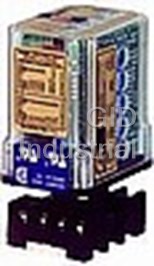
ABSOLUTE PROCESS INSTRUMENTS API7580G
Description
Absolute Process Instruments API7580G Transition Modules-FREQUENCY TRANSMITTER
Part Number
API7580G
Price
Request Quote
Manufacturer
ABSOLUTE PROCESS INSTRUMENTS
Lead Time
Request Quote
Category
PRODUCTS - A
Specifications
A230 option
230 VAC ±10%, 50/60 Hz, 2.5 W max.
Bipolar Voltage
±1 VDC ±10 VDC
Current (20 V compliance)
0-2 mADC 0-20 mADC
D option
9-30 VDC, 2.5 W typical
High range
min 0-2 kHz max 0-30 kHz Increments 2 kHz
Input Amplitude Range
100 mV to 150 VRMS System voltages must not exceed socket voltage rating
Input Impedance
10 kO nominal (maximum sensitivity)100 kO nominal (minimum sensitivity)
Input Loop Power Supply
18 VDC nominal, unregulated, 25 mADC, max. ripple, less than 1.5 Vp-p
Low range
min. 0-100 Hz max.0-1500 Hz Increments 100 Hz
Maximum sensitivity
±25 mV typical
Minimum sensitivity
±2.5 V typical
P option
80-265 VAC or 48-300 VDC, 50/60 Hz, 2.5 W typical
Response Time
Low ranges: 600 milliseconds. typical;High ranges: 110 milliseconds. typical
Standard
115 VAC ±10%, 50/60 Hz, 2.5 W max.
Voltage
0-1 VDC 0-10 VDC
Features
- 2000 V Full Isolation Input/Output/Power
- 30 Selectable Inputs & 16 Selectable Outputs
- Adjustable Input Sensitivity (Hysteresis)
- Functional Test Pushbutton
- Input and Output Looptracker LEDs
- Setup via Rotary Switches & Easy-to-Use Tables
Datasheet

Extracted Text
Frequency Frequency to DC Transmitter, Isolated API 7580 G Input: 0-100 Hz to 0-30 kHz Wide Ranging I/O Output: 0-1 V to ±10 VDC, 0-2 mA to 4-20 mADC One Minute Setup! ● ● 30 Selectable Inputs & 16 Selectable Outputs ● ● Setup via Rotary Switches & Easy-to-Use Tables ● ● 2000 V Full Isolation Input/Output/Power Variable ● ● Brightness Adjustable Input Sensitivity (Hysteresis) 2.75" Input LED ® ● ● Input and Output Looptracker LEDs Output Test Button ● ● Functional Test Pushbutton 2.38" Output Test Applications Adjust ■■ Monitor and Control Motor or Line Speed Output Calibration ■■ Convert a Square Wave Output to 4-20 mA Variable Brightness Specifications Output LED Input Ranges Socket Sold Minimum Maximum Range Increments Separately Low range: 0-100 Hz 0-1500 Hz 100 Hz High range: 0-2 kHz 0-30 kHz 2 kHz Input Impedance 10 kΩ nominal (maximum sensitivity) 100 kΩ nominal (minimum sensitivity) Free Factory Free Factory Input & Output Input & Output Input Sensitivity/Hysteresis Calibration! Calibration! Single turn potentiometer for sensitivity adjustment Maximum sensitivity: ±25 mV typical Minimum sensitivity: ±2.5 V typical Description and Features Input Amplitude Range 100 mV to 150 V System voltages must not exceed socket voltage rating RMS The API 7580 G accepts a frequency Input and provides an optically isolated DC voltage or current analog output that is linearly proportional to the input. Input Waveform Common applications include frequency to DC conversions from frequency out- Sine wave Sawtooth Square wave put type devices such as rotary encoders, magnetic pick-ups, variable speed Most other waveforms with greater than 100 mV amplitude change drives and flow meters. For PLCs that do not have analog outputs, often the Input Loop Power Supply pulse rate of a discreet output can be programmed to vary. By connecting the 18 VDC nominal, unregulated, 25 mADC, max. ripple, less than 1.5 V p-p API 7580 G to this output, a proportional analog signal can be generated. LoopTracker The full 3-way (input, output, power) isolation makes this module useful for Variable brightness LEDs indicate input/output loop level and status ground loop elimination, common mode signal rejection or noise pickup reduc- tion. Output Ranges Minimum Maximum Load Factor The API 7580 G input and output can be field-configured via external rotary and Voltage: 0-1 VDC 0-10 VDC slide switches. The more common ranges (30 input & 16 output) can be select- Bipolar Voltage: ±1 VDC ±10 VDC ed from the table on the module. Many additional combinations are possible. Current (20 V compliance): 0-2 mADC 0-20 mADC 1000 Ω at 20 mA Consult the factory for assistance with special ranges. Consult factory for other ranges API exclusive features include two LoopTracker LEDs and a Functional Test Output Zero and Span Pushbutton. The LoopTracker LEDs (Green for input, Red for output) vary in Multiturn potentiometers to compensate for load and lead variations intensity with changes in the process input and output signals. Monitoring the Zero: ±15% of span adjustment range typical state of these LEDs can provide a quick visual picture of your process loop at Span: ±10% of span adjustment range typical all times. The functional test pushbutton provides a fixed output (independent of the input) when held depressed. The test output level can be field-adjusted via Functional Test Button a multiturn potentiometer. Sets output to test level when pressed. Adjustable 0-100% of span. Potentiometer factory set to approx. 50% of span Both the LoopTracker LEDs and functional test pushbutton greatly aid in saving time during initial startup and/or troubleshooting. The built-in 18 VDC unregulat- Response Time ed loop excitation power supply can be used to power passive input devices. Low ranges: 600 milliseconds. typical High ranges: 110 milliseconds. typical Accuracy Models & Options Better than ±0.2% of span including hysteresis, linearity and adjustment reso- API 7580 G Field rangeable frequency to DC transmitter, lution. Better than ±0.8% repeatability isolated, with loop power supply, 115 VAC Isolation Options—Add to end of model number 2000 V min. Full isolation: power to input, power to output, input to output RMS P Powered by 80-265 VAC or 48-300 VDC, 50/60 Hz A230 Powered by 230 VAC, 50/60 Hz Ambient Temperature Range and Stability D Powered by 9-30 VDC –10°C to +60°C operating ambient U Conformal coating for moisture resistance Better than ±0.02% of span per °C stability Accessories—Order as separate line item Power API 008 8-pin socket Standard: 115 VAC ±10%, 50/60 Hz, 2.5 W max. API 008 FS 8-pin finger-safe socket P option: 80-265 VAC or 48-300 VDC, 50/60 Hz, 2.5 W typical API TK36 DIN rail, 35 mm W x 39" L, aluminum A230 option: 230 VAC ±10%, 50/60 Hz, 2.5 W max. D option: 9-30 VDC, 2.5 W typical 1220 American Way Libertyville, IL 60048 © 09-09 Phone: 800-942-0315 Fax: 800-949-7502 api-usa.com BSOLUTE ROCESS NSTRUMENTS, Inc. 157 2 3 3 2 2 1 1 1 0 0 0 F F 9 E E D D 8 API 7580 G Installation and Setup ELECTRICAL CONNECTIONS CALIBRATION WARNING! All wiring must be performed by qualified personnel only. Input & Output Ranges – Range are pre-set at the factory as specified on your This module requires an industry-standard 8-pin socket. Order API 008 or fin- order. Top-mounted, Zero and Span potentiometers can be used should fine- ger-safe API 008 FS socket separately. tuning be necessary. Custom ranges may require factory modification. Power Input Terminals – The white label on the side of the API module will 1. Apply power to the module and allow a minimum 20 minute warm up time. indicate the power requirements. AC power is connected to terminals 1 and 3. 2. Using an accurate frequency calibration source, provide an input to the mod- For DC powered modules, polarity MUST be observed. Positive (+) is wired to ule equal to the minimum input required for the application. terminal 1 and negative (–) is wired to terminal 3. 3. Using an accurate measurement device for the output, adjust the Zero Powered Signal Input – Observe polarity when connecting the signal input. potentiometer for the exact minimum output desired. The Zero control The positive signal (+) is wired to terminal 5 and negative (–) to terminal 6. should only be adjusted when the input signal is at its minimum. This will pro- AC or DC (–) duce the corresponding minimum output signal of 0 Hz. 4. Set the input at maximum, and then adjust the Span pot for the exact maxi- Module Power 3 2 No mum output desired. The Span control should only be adjusted when the connection input signal is at its maximum. This will produce the corresponding maximum AC or DC (+) 4 1 output signal. (+) Powered 5 8 PLC, Display, 5. Repeat adjustments for maximum accuracy. 2 Wire (–) (–) Recorder, Etc. Input Sensitivity Adjust – This single turn potentiometer located on the side of the 6 7 (+) Device (+) module provides an adjustable threshold level that the incoming signal must (–) Socket top view overcome before an output can be produced. This is used to limit noise and min- imize false input signals that may cause erroneous readings. API 7580 G typical wiring with powered input and standard output When fully clockwise (maximum sensitivity), the input threshold is typically ±25 Passive Signal Input Using the 18 V Supply – Polarity must be observed mV. In the fully counterclockwise position (minimum sensitivity), the input when connecting the signal input. A passive input device can be powered by the threshold is typically ±2.5 Volts. 18 volt DC power supply at terminal 4 (+) and terminal 5 (–). This may save the Test Range Adjust – Turn the multi-turn Test Range potentiometer while hold- expense of purchasing a separate power supply for the input device. A typical ing the Test button depressed until the desired output test level is reached. It example is shown, however consult the manufacturer of your specific sensor to can be adjusted to vary the output signal from 0 to 100% of the output range. determine its compatibility and proper wiring. Signal Output Terminals – Polarity must be observed when connecting the OPERATION signal output to the load. The positive connection (+) is connected to terminal 7 The frequency input to the API 7580 G is capacitively coupled (to remove any and the negative (–) is connected to terminal 8. The API 7580 G provides a DC component at the input) to a comparator whose threshold is determined by powered output to drive the output loop. the setting of the sensitivity control. The output from the comparator passes through an opto-coupler to the output stage. AC or DC (–) Test Button – Drives a device on the output side of the loop (a panel meter, Module Power chart recorder, etc.) with a known good signal that can be used as a system 3 2 Passive diagnostic aid during initial start-up or during troubleshooting. When released, (+) (+) 4 1 AC or DC (+) 2 Wire the output will return to normal. ® Input GREEN LoopTracker Input LED – Provides a visual indication that a signal is 5 8 PLC, Display, Device (–) (–) (–) (–) being sensed by the input circuitry of the module. The LED illuminates when the Recorder, Etc. 6 7 input is sufficiently large to trigger the input comparator depending on the input (+) (+) sensitivity adjustment. It also indicates the input signal range by changing in No connection Socket top view intensity as the frequency changes from minimum to maximum. If the LED fails Using the built-in 18 VDC loop supply to power a passive input device to illuminate, or change in intensity as the frequency changes, it may indicate a problem with module power, or signal input wiring. RANGE SELECTION RED LoopTracker Output LED – Provides a visual indication that the output Three rotary switches and two slide switches located on the side of the module signal is functioning. It becomes brighter as the input and the corresponding are used to select input and output ranges. Most popular ranges are listed on output change from minimum to maximum. For current outputs, the RED LED the module labels and the table at right. See www.api-usa.com or contact fac- will only light if the output loop current path is complete. For either current or tory for special ranges. Sensitivity Adjustment voltage outputs, failure to illuminate or a failure to change in intensity as the 1. Set the Output Select 2 slide process changes may indicate a problem with the module power or signal out- switch “A” to current (I) or voltage 7580G put wiring. (V) depending on output type. Output Input Frequency Inputs VOLTAGE Outputs CURRENT Outputs Select 2 Output Range 1 Input 2. Set the Input Range 1 slide I V Range 2 Select 1 Offset L H 50 VDC or 150 VAC Maximum Switch A To “V” Switch A To “I” switch “E” to either L or H AB C DE Range B E Range B E Range C D Range C D depending on input frequency C C 0-100 Hz 1 LO 0-2 kHz 1 HI 0-1 V 0 8 0-2 mA 0 8 range. 0-200 Hz 2 LO 0-4 kHz 2 HI 0-2 V 1 8 2-10 mA 2 6 For frequencies from 0-100 Hz 0-300 Hz 3 LO 0-6 kHz 3 HI 0-4 V 2 8 0-10 mA 3 8 thru 0-1500 Hz, switch “E” is 0-400 Hz 4 LO 0-8 kHz 4 HI 1-5 V 2 6 0-16 mA 5 8 placed in the L position. 0-500 Hz 5 LO 0-10 kHz 5 HI 0-5 V 3 8 0-20 mA 6 8 For frequencies from 0-2000 Hz thru 0-30 kHz, switch “E” is placed in the H 0-600 Hz 6 LO 0-12 kHz 6 HI 0-8 V 5 8 4-20 mA 5 6 position. 0-700 Hz 7 LO 0-14 kHz 7 HI 2-10 V 5 6 3. Find your input frequency range and set Input Range 2 rotary switch “B”. 0-800 Hz 8 LO 0-16 kHz 8 HI 0-10 V 6 8 0-900 Hz 9 LO 0-18 kHz 9 HI ±5 V 6 B 4. Find your output range and set Output Range “C” and Output Offset “D”. 0-1000 Hz A LO 0-20 kHz A HI ±10 V 8 B 5. The Zero, Span, Sensitivity, and Test Range potentiometers can now be 0-1100 Hz B LO 0-22 kHz B HI adjusted. 0-1200 Hz C LO 0-24 kHz C HI Depending on the rotary switch settings, the input is filtered, either amplified or 0-1300 Hz D LO 0-26 kHz D HI attenuated as required, then passed through an optical isolation circuit to the 0-1400 Hz E LO 0-28 kHz E HI output stage. 0-1500 Hz F LO 0-30 kHz F HI 1220 American Way Libertyville, IL 60048 For latest product information or to contact Phone: 800-942-0315 Fax: 800-949-7502 your local representative visit api-usa.com © 02-09 158 BSOLUTE ROCESS NSTRUMENTS, Inc. 7 B B A A 6 9 9 Frequency 8 5 8 7 7 4 6 6 5 5 3 4 4 Frequency Application Information API 7580 G Auto-Ranging Flow Meter PROBLEM SOLUTION A flow in a process must be accurately measured throughout a wide An API 7580 G Field Selectable Isolated Frequency to DC Transmitter range. The flow rate is used by a PLC to control the process. Two flow module is used with each flow meter to convert the frequency output to meters are utilized, one very accurate at low flow and one very accu- a 0-10 VDC signal proportional to flow. An API 1080 DIN DC Input, rate at high flow. A means for automatic selection of the appropriate Wide Ranging, Field Selectable Single Alarm Trip module monitors the flow meter is required. flow rate and transfers the PLC analog input to the flow meter appro- priate for that range. or 1080 DIN The second set of relay contacts of the API 1080 DIN provides a PLC binary input with a closure to indicate which flow meter is selected. Controlling and Recording Water Flow PROBLEM SOLUTION A process requires a controlled water flow which must also be record- A linear flow meter and a control valve are installed in the water line. ed. Power for the flow meter is provided by the +18 VDC loop excitation supply available as standard on an API 7580 G Field Selectable Isolated Frequency to DC Transmitter module. The API 7580 G con- verts the frequency output of the flow meter to a 4-20 mA signal which is used to control and monitor the flow to the process. The API 7580 G features 30 selectable input ranges from 0-100 Hz to 0-30 KHz, and 16 selectable output ranges. In addition, the optical isola- tion protects against unwanted ground loops and electrical noise. FREE APPLICATION ASSISTANCE Call Customer Service API maintains a constant effort to upgrade and improve its products. Specifications 800-942-0315 are subject to change without notice. Consult factory for your specific requirements. 1220 American Way Libertyville, IL 60048 © 01-07 Phone: 800-942-0315 Fax: 800-949-7502 api-usa.com BSOLUTE ROCESS NSTRUMENTS, Inc. 159 API 7580 G Application Information Monitoring and Totalizing Flow Meter Output PROBLEM SOLUTION The frequency output signal of a flow meter must be monitored by a An API 7580 G Isolated Frequency to DC Transmitter module is con- DCS as well as a remotely located counter/totalizer. The counter/total- nected to the frequency output of the flow meter. The API 7580 G has izer accepts a TTL frequency input. a built-in loop power supply to power the current loop. The 7580 G converts the frequency to a 4-20 mA output which is sent to the DCS and an API 7500G M02 mounted near the remote counter/total- izer. The API 7500 G M02 converts the 4-20 mA signal to a TTL frequency signal for the counter/totalizer. HVAC Variable Air Volume Control PROBLEM SOLUTION The constant volume heating, ventilating and air conditioning (HVAC) The room temperature sensor and valve position feedback potentiome- system for a wet chemistry laboratory is being converted to variable air ters are monitored by the eight room controller analog inputs, and the volume (VAV) to save energy. The amount of air exhausted by four supply air and the auxiliary supply air valves are controlled by the two fume hoods in the lab will vary depending upon their sash positions. A 1-10 VDC analog outputs. room controller must monitor the room temperature, the quantity of air exhausted and the quantity of air supplied, and operate supply air, aux- iliary supply air, and general exhaust air valves to maintain room tem- perature, room pressure and a minimum number of air changes per hour for comfort and safety. The room controller has 8 analog inputs, 2 analog outputs and 1 frequency output, but 3 analog outputs are required. Frequently Asked Questions We have a PNP proximity sensor powered by the 18 VDC API 7580 G loop supply. It reads the flywheel gear teeth and a sends a frequency signal to the API 7580 G and works fine throughout the range. However, if the wheel is stopped with a tooth in-line with the sensor, the output will stay high (PNP output) and the API 7580 G output will go high to the maximum of the range. How can we prevent this? The +18 volt loop supply from the API 7580 G has a maximum ripple of 1.5 Vp-p so the high output from the prox sensor will have this ripple. The signal input to the 7580 G has a capacitor in series so any DC input charges and then opens the circuit. However, with the ripple, there will be a 50/60 Hertz signal present. You must use a magnetic pick-up in place of the proximity sensor since the amplitude signal from the magnetic pick-up will decrease as the flywheel slows down and when stopped, there will be no amplitude even with a tooth in-line with the sensor head. The magnetic pick-up generates its own signal as the field changes. When the field stops changing, the signal goes to zero. 1220 American Way Libertyville, IL 60048 For latest product information or to contact Phone: 800-942-0315 Fax: 800-949-7502 your local representative visit api-usa.com © 01-07 160 BSOLUTE ROCESS NSTRUMENTS, Inc. Frequency
Frequently asked questions
What makes Elite.Parts unique?

What kind of warranty will the API7580G have?
Which carriers does Elite.Parts work with?
Will Elite.Parts sell to me even though I live outside the USA?
I have a preferred payment method. Will Elite.Parts accept it?
Why buy from GID?

Quality
We are industry veterans who take pride in our work

Protection
Avoid the dangers of risky trading in the gray market

Access
Our network of suppliers is ready and at your disposal

Savings
Maintain legacy systems to prevent costly downtime

Speed
Time is of the essence, and we are respectful of yours
Related Products

OCTAL BASE 8 PIN
INSULATOR
BRIDGE TO DC TRANSMITTER
BRIDGE TO DC TRANSMITTER
INSULATOR
Request a Quote

The quote request has been received
Close

Facing challenges or have inquiries? Feel free to contact us!
Call Us +1-469-283-2440
What they say about us
FANTASTIC RESOURCE
One of our top priorities is maintaining our business with precision, and we are constantly looking for affiliates that can help us achieve our goal. With the aid of GID Industrial, our obsolete product management has never been more efficient. They have been a great resource to our company, and have quickly become a go-to supplier on our list!
Bucher Emhart Glass
EXCELLENT SERVICE
With our strict fundamentals and high expectations, we were surprised when we came across GID Industrial and their competitive pricing. When we approached them with our issue, they were incredibly confident in being able to provide us with a seamless solution at the best price for us. GID Industrial quickly understood our needs and provided us with excellent service, as well as fully tested product to ensure what we received would be the right fit for our company.
Fuji
HARD TO FIND A BETTER PROVIDER
Our company provides services to aid in the manufacture of technological products, such as semiconductors and flat panel displays, and often searching for distributors of obsolete product we require can waste time and money. Finding GID Industrial proved to be a great asset to our company, with cost effective solutions and superior knowledge on all of their materials, it’d be hard to find a better provider of obsolete or hard to find products.
Applied Materials
CONSISTENTLY DELIVERS QUALITY SOLUTIONS
Over the years, the equipment used in our company becomes discontinued, but they’re still of great use to us and our customers. Once these products are no longer available through the manufacturer, finding a reliable, quick supplier is a necessity, and luckily for us, GID Industrial has provided the most trustworthy, quality solutions to our obsolete component needs.
Nidec Vamco
TERRIFIC RESOURCE
This company has been a terrific help to us (I work for Trican Well Service) in sourcing the Micron Ram Memory we needed for our Siemens computers. Great service! And great pricing! I know when the product is shipping and when it will arrive, all the way through the ordering process.
Trican Well Service
GO TO SOURCE
When I can't find an obsolete part, I first call GID and they'll come up with my parts every time. Great customer service and follow up as well. Scott emails me from time to time to touch base and see if we're having trouble finding something.....which is often with our 25 yr old equipment.
ConAgra Foods