

 Manufacturers
ABB MT/S 4.12.2M
Description
ABB MT/S 4.12.2M Sensor
Part Number
MT/S 4.12.2M
Price
Request Quote
Manufacturer
ABB
Lead Time
Request Quote
Category
PRODUCTS - M
Datasheet

Extracted Text
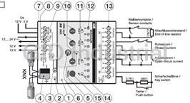
Montage- und Betriebsanleitung 1 Installation and Operating Instructions Mode d´emploi Montage- en bedieningshandleiding IP20 Istruzioni per l´uso +45 °C Instrucciones de montaje de servicio Bruksanvisning för montering och drift -5 °C MT/S 4.12.2M, MT/S 8.12.2M DE Sicherheitsterminal, 4- und 8fach EN Security Terminal, 4- and 8-fold FR Terminal de sécurité, 4- et 8-fois NL Veiligheidsterminal, 4- en 8-voudig ABB STOTZ-KONTAKT GmbH IT Terminale di sicurezza, 4- e 8-livelli Eppelheimer Straße 82, 69123 Heidelberg, Germany ES Terminal de seguridad , 4- y 8-veches Postfach 10 16 80, 69006 Heidelberg, Germany SE Säkerhetsterminal, 4- och 8-faldig v +49 (0) 6221 701 607 6 +49 (0) 6221 701 724 www.abb.de/stotz-kontakt ® ABB i-bus KNX www.abb.de/knx 2CDG 941 072 P0001 Technische Hotline / Technical Support: v +49 (0) 6221 701 434 E-Mail: knx.hotline@de.abb.com Technische Daten (Auszug) Verschmutzungsgrad 2 nach DIN EN 60664-1 Taste Montage DE 1 Busspannung 21...30 V DC, erfolgt über KNX Approbation KNX nach 50090-1, -2 Das Gerät ist geeignet zum Einbau in Verteilern oder Kleingehäusen zum manuellen Rücksetzen des Gerätezustands. Rücksetzen über Stromaufnahme (KNX) < 6 mA Maße (H x B x T) 90 x 72 x 64,5 mm für Schnellbefestigung auf 35 mm Tragschienen, nach DIN EN a Schildträger Tastendruck. Freigabe und Sperren über ETS. Bei einem Reset Hilfsspannung 12 V DC ± 1,6 V, SELV Einbaubreite 4 Module à 18 mm 60715. Wichtige Hinweise b und c Programmier-LED und -Taste blinken die Meldergruppen-LEDs mehrmals kurz auf. Stromaufnahme (12 V DC) max. 64 mA ohne Die Zugänglichkeit des Gerätes zum Betreiben, Prüfen, Besichtigen, Montage und Inbetriebnahme darf nur von Elektrofachkräften ausgeführt d Busanschlussklemme LED (gelb) Bedienung und Anzeige ext. Verbraucher (4fach) Warten und Reparieren muss sichergestellt sein. werden. Bei der Planung und Errichtung von elektrischen Anlagen sowie e und f LED und Taste für manuelle Bedienung max. 83 mA ohne Programmiertaste sicherheitstechnischen Anlagen für Einbruch- und Branderkennung ext. Verbraucher (8fach) g Relaisausgänge (2, 3) zeigt an, ob das Gerät unscharf/scharf ist. zur Vergabe der physikalischen Adresse. Anschluss sind die einschlägigen Normen, Richtlinien, Vorschriften und Eingänge h potentialfreier Relaisausgang (1) EIN: Gerät im unscharfen Zustand. Programmier-LED (rot) Der elektrische Anschluss für die Hilfsspannungsversorgung erfolgt Bestimmungen des jeweiligen Landes zu beachten. Dieses Gerät ist Leerlaufspannung 12 V DC i 12 V DC Hilfsspannung (0V, 12V) AUS: Gerät im scharfen Zustand. über Schraubklemmen. Der Anschluss an den EIB / KNX erfolgt durch ist an, nachdem die Programmiertaste gedrückt wurde, um dem keine Brandmelderzentrale gemäß EN 54-2 /-4. Kurzschlussstrom 6 mA j Taste (Out 1-Out 3) aufstecken der Busanschlussklemme. Die Klemmenbezeichnungen Busteilnehmer eine physikalische Adresse zu vergeben Blinkt: Einbruchalarm - Gerät bei Transport, Lagerung und im Betrieb zulässiger Leitungswiderstand max. 200Ω befinden sich auf dem Gehäuse. k LED (Out 1-Out 3) LED A...H (rot) Taste vor Feuchtigkeit, Schmutz und Beschädigung schützen! Ausgänge l LED Meldergruppen (A-D od. A-H) zeigt den Zustand der Meldergruppe an. - Gerät nur innerhalb der spezifizierten technischen Daten betreiben! zur Umschaltung zwischen KNX-Betrieb und manueller Bedie- Typ monostabile Relais Inbetriebnahme - Gerät nur im geschlossenen Gehäuse (Verteiler) betreiben! m Meldergruppen (A-D od. A-H) nung. Umschaltvorgang über Tastendruck. Freigabe und Sperren EIN: Meldergruppe ausgelöst Die Vergabe der physikalischen Adresse sowie das Einstellen der Kurzschlussstrom 0,6 A n LED (Unscharf/Scharf) AUS: Meldergruppe in Ruhe über ETS. Nennspannung 12...24 V DC (Relais 1) Parameter erfolgt mit der Engineering Tool Software ETS (ab Version Reinigen o Taste Reset Blinkt: Alarmspeicher LED (gelb) 12 V DC (Relais 2 u. 3) ETS2 V1.2 oder höher). Für die Programmierung in der ETS3 ist das Verschmutzte Geräte können mit einem trockenen Tuch gereinigt 2 Blinkt schnell: Sabotagealarm Anschlussklemmen 0,2…2,5 mm feindrahtig zeigt den Zustand des manuellen Betriebs an. entsprechende VD3-File zu verwenden. werden. Reicht dies nicht aus, kann ein mit Seifenlösung leicht Geräte-Beschreibung 2 0,2…2,5 mm eindrahtig EIN: Gerät befindet sich im manuellen Betrieb angefeuchtetes Tuch benutzt werden. Auf keinen Fall dürfen ätzende Die Sicherheitsterminals MT/S 4.12.2M und MT/S 8.12.2M finden Anziehdrehmoment max. 0,6 Nm Bei Ausfall der 12 V DC Hilfsspannung blinken alle Meldergruppen- AUS: Gerät befindet sich im KNX-Betrieb Mittel oder Lösungsmittel verwendet werden. Anwendung als Schnittstelle zwischen Sensoren der Sicherheitstechnik LEDs. Blinkt schnell: Umschaltvorgang und dem KNX. Die Geräte besitzen 4 bzw. 8 Eingänge, sogenannte Temperaturbereich Meldergruppen. Sie dienen dem überwachten Anschluss von passiven Taste Wartung im Betrieb -5°C…+45°C Eine ausführliche Beschreibung der Parametrierung und Meldern (z.B. Magnetkontakten und/oder Glasbruchsensoren) an ABB Hinweis: Das Gerät ist wartungsfrei. Bei Schäden (z.B. durch Transport, Lagerung) Lagerung -25°C…+55°C zum manuellen Ein- und Ausschalten der Ausgänge. Umschalt- ® Inbetriebnahme finden Sie im Produkthandbuch des Gerätes. i-bus KNX und/oder zum Anschluss von potentialfreien Kontakten in dürfen keine Reparaturen vorgenommen werden. Transport -25°C…+70°C Die manuelle Bedienung ist werkseitig freigegeben. Sperren über vorgang über Tastendruck. Freigabe und Sperren über ETS. Dieses finden Sie zum Download im Internet unter www.abb.de/knx. Anwendung mit erhöhten Sicherheitsanforderungen. max. Feuchte 93%, keine Betauung LED Out 1...3 (gelb) ETS. Die Geräte können als System mit selbständiger Alarmlogik oder in Bei Öffnen des Gerätes erlischt der Gewährleistungsanspruch! Zeigt den Zustand des jeweiligen Ausgangs an. Kombination mit dem Sicherheitsmodul oder einer Einbruchmeldeanlage Schutzart IP 20 nach DIN EN 60529 mit KNX Schnittstelle verwendet werden. EIN: Ausgang ist eingeschaltet Schutzklasse II nach DIN EN 61140 Überspannungskategorie III nach DIN EN 60664-1 AUS: Ausgang ist ausgeschaltet Technical data (excerpt) Pollution class 2, DIN EN 60664-1 compliant Key Installation EN 1 Bus voltage 21...30 V DC, supplied via KNX Certification KNX according to 50090-1, -2 For manually resetting the state of the device. Resetting via press The unit is designed to be installed in distribution boxes or small Current consumption (KNX) < 6 mA Dimensions (H x W x D) 90 x 72 x 64.5 mm a Label carrier of the key. Enabling and blocking via ETS. During a reset the LEDs housings for quick mounting on 35 mm support rails in accordance Auxiliary voltage 12 V DC ± 1.6 V, SELV Mounting width 4 modules of 18 mm Important notes b and c Programming LED and programming key of the detector groups flash briefly several times. with DIN EN 60715. Current consumption (12V DC) Max. 64 mA without external Only skilled electricians are authorised to install and to start the device. d Bus connection terminal LED (yellow) Ensure proper access to the unit for operation, testing, inspection, Operation and display consumer (4-fold) When planning and setting up electrical installations as well as security e and f LED and key for manual operation Max. 83 mA without external maintenance and repair. Programming key systems for the protection against intrusion and fire, all the relevant consumer (8-fold) g Relay outputs (2, 3) Displays whether the device is not activated or activated. standards, guidelines, rules and regulations of the respective country to assign the physical address. Inputs must be adhered to. This device is not a fire alarm control center h Floating relay output (1) ON: Device is unset. Connection Programming LED (red) No-load voltage 12V DC according to EN 54-2 /-4. i 12 V DC auxiliary voltage (0V, 12V) OFF: Device is set. The electrical connection for the auxiliary voltage supply is made via Is ON after the programming key has been pressed, in order to Short-circuit current 6 mA - Protect the unit against humidity, dirt and damage during transport, j Key (Out 1-Out 3) assign a physical address to the bus member. Flashing: Intrusion alarm screw terminals. The connection to the EIB / KNX is made by plugging Admissible line resistance Max. 200Ω storage and operation! k LED (Out 1-Out 3) LED A ...H (red) onto the bus terminal. The terminals are identified on the housing. Key - Always operate the unit within the specified technical data! Outputs l LED zones (A-D or A-H) Displays the status of the zones. - Operate the unit only in a sealed housing (distribution box)! For switching between KNX mode and manual operation. Type Monostable relay m Zones (A-D or A-H) Switchover via press of the key. Enabling and blocking via ETS. ON: Zones triggered Start-up Short-circuit current 0.6 A Cleaning n LED (unset/set) OFF: Zones at rest The Engineering Tool Software ETS (as of version ETS V1.2 or higher) Nominal voltage 12...24V DC (Relay 1) Soiled units can be cleaned with a dry cloth. If this is not sufficient, you o Reset key Flashing: Alarm memory is used to assign the physical address and to set the parameters. LED (yellow) 12V DC (Relay 2 and 3) can also use a cloth that is slightly impregnated with a soap solution. Flashes rapidly: Sabotage alarm Make sure you use the VD3 file when programming in ETS3. Terminals 0.2…2.5 mm², fine-wire Displays the manual operating status. Do not use corrosive agents or solvents. Device description 0.2…2.5 mm² single-wire ON: The unit is in manual mode Security terminals MT/S 4.12.2M and MT/S 8.12.2M find application as Tightening torque 0.6 Nm max. Maintenance All LEDs of the zones flash when the 12V DC auxiliary voltage OFF: The unit is in KNX mode interface between security technology sensors and the KNX. The device Temperature range The unit is maintenance-free. Do not carry out any repairs when the fails. has 4 or 8 inputs, so-called zones. They serve as monitored connec- Flashes rapidly: Switchover in progress during operation -5° C…+45° C unit is damaged (e.g. during transport, storage). tion of passive detectors (e.g. magnetic contacts and/or glassbreak Key A detailed description of the parameterisation and start-up process Storage -25° C…+55° C ® sensors) to ABB i-bus KNX and/or connection of floating contacts in Note: can be found in the product manual of the device. You can download Transport -25° C…+70° C For switching outputs on and off manually. Switchover via press Opening the unit voids the warranty! high-security applications. Maximum humidity 93%, no condensation Manual operation is enabled at the factory. It is blocked via ETS. it on the Internet at www.abb.de/knx. of the key. Enabling and blocking via ETS. The devices can be used as system with stand-alone alarm logic or LED Out 1...3 (yellow) in combination with the Security Module or an intrusion alarm system Protection IP 20 in acc. with DIN EN 60529 Displays the status of the respective output. with KNX interface. Safety class II, DIN EN 61140 compliant ON: Output is switched on Overvoltage class III, DIN EN 60664-1 compliant OFF: Output is switched off Montage Caractéristiques techniques (extrait) Catégorie de surtension III selon la norme DIN EN 60664-1 Touche FR 1 Tension du bus 21...30 V c.c., via le KNX Degré de contamination 2 selon la norme DIN EN 60664-1 pour la réinitialisation manuelle de l‘état de l‘appareil. Réinitialisa- L‘appareil est adapté à un montage dans un tableau de distribution Consommation de courant (KNX) < 6 mA Certification KNX selon 50090-1, -2 a Support de plaque tion par appui sur la touche. Activation et blocage via ETS. En cas ou dans un petit boîtier pour une fixation rapide sur des profilés Tension auxiliaire 12 V c.c. ± 1,6 V, SELV Dimensions (H x l x P) 90 x 72 x 64,5 mm Remarques importantes support de 35 mm, conformément à la norme DIN EN 60715. b et c DEL et touche de programmation de réinitialisation, les DEL des groupes de détecteurs clignotent Consommation de courant Largeur de montage 4 modules à 18 mm Le montage et la mise en service ne doivent être effectués que par d Borne de connexion du bus L‘accès à l‘appareil doit être possible pour son utilisation, son plusieurs fois pendant un court instant. (12 V c.c.) 64 mA maxi. sans des électrotechniciens. Lors de la planification et de la mise en place e et f DEL et touche pour la commande manuelle consommateur ext. (4-fois) Utilisation et affichage DEL (jaune) contrôle, son inspection, sa maintenance et sa réparation des installations électriques ainsi que des installations techniques de 83 mA maxi. sans Touche de programmation g Sorties de relais (2, 3) sécurité pour la détection des incendies et effractions, il convient de consommateur ext. (8-fois) respecter les normes, directives, réglementations et prescriptions h Sortie de relais sans potentiel (1) pour attribuer l‘adresse physique. Raccordement indique si l‘appareil est en alerte/n‘est pas en alerte. Entrées locales applicables. Cet appareil n‘est pas une centrale de détection i Tension auxiliaire 12 V c.c. (0 V, 12 V) DEL de programmation (rouge) ALLUMEE : L‘appareil n‘est pas en alerte. Le raccordement électrique pour l‘alimentation en tension auxiliaire Tension en circuit ouvert 12 V c.c. anti-incendie selon EN 54-2 /-4. est allumée lorsque la touche de programmation a été actionnée j Touche (Out 1-Out 3) ETEINTE : L‘appareil est en alerte. s‘effectue à l‘aide de bornes à vis. Le raccordement au EIB / KNX Intensité de court-circuit 6 mA - Protéger l‘appareil contre l‘humidité, la poussière et les dommages k DEL (Out 1-Out 3) afin de donner une adresse physique au participant du bus se fait en branchant la borne de connexion du bus. La description Résistivité du circuit admissible 200 Ω maxi. Clignote : Alarme d‘effraction pendant le transport, le stockage et l‘utilisation ! l Groupes de détecteurs à DEL (A-D ou A-H) Touche DEL A...H (rouge) des bornes se trouve sur le boîtier. - Utiliser l‘appareil uniquement dans les limites spécifiées dans les Sorties caractéristiques techniques ! m Groupes de détecteurs (A-D ou A-H) Pour la commutation entre le mode KNX et le mode de fonction- indique l‘état du groupe de détecteurs. Type Relais monostable - Utiliser l‘appareil uniquement dans un boîtier fermé (tableau de nement manuel. Commutation par appui sur la touche. Activation Mise en service n DEL (pas en alerte/en alerte) ALLUMEE : Groupe de détecteurs déclenché Intensité de court-circuit 0,6 A distribution). o Touche de réinitialisation et blocage via ETS. L‘attribution de l‘adresse physique ainsi que le réglage des ETEINTE : Groupe de détecteurs au repos Tension nominale 12...24 V c.c. (relais 1) DEL (jaune) Clignote : Mémoire des alarmes paramètres se font par l‘intermédiaire du logiciel Engineering 12 V c.c. (relais 2 et 3) Nettoyage Description de l‘appareil Bornes de raccordement 0,2... 2,5 mm² à fils de faible indique l‘état du mode manuel. Tool Software ETS (version ETS2 V1.2 ou supérieure). Pour la Clignote rapidement : Alarme de sabotage Les appareils salis peuvent être nettoyés avec un chiffon sec. Si cela ne Les terminaux de sécurité MT/S 4.12.2M et MT/S 8.12.2M sont utilisés diamètre ALLUMEE : L‘appareil est en mode manuel programmation dans l‘ETS3, il faut utiliser le VD3-File correspondant. suffit pas, utiliser un chiffon imbibé de solution savonneuse. Il ne faut en comme interface entre des capteurs de la technique de sécurité et le 0,2…2,5 mm² monoconducteur aucun cas utiliser des produits corrosifs ou des solvants. ETEINTE : L‘appareil est en mode KNX En cas de coupure de la tension auxiliaire 12 V c.c., toutes les KNX. Les appareils comprennent 4 ou 8 entrées, appelées groupes Couple de serrage 0,6 Nm maxi Clignote rapidement : Commutation DEL des groupes de détecteurs clignotent. de détecteurs. Elles servent au raccordement surveillé de détecteurs Plage de température Maintenance passifs (par ex. des contacts magnétiques et/ou des capteurs de bris Touche en fonctionnement -5 °C…+45 °C Cet appareil ne nécessite pas de maintenance. En cas d‘endommagement ® de glace) sur l‘ABB i-bus KNX et/ou au raccordement de contacts sans stockage -25 °C…+55 °C pour l‘activation et la désactivation manuelles des sorties. Com- Nota : Vous trouverez une description détaillée du paramétrage et de la (par ex. lors du transport, du stockage), aucune réparation ne doit être potentiel en cas d‘utilisation avec des exigences de sécurité élevées. transport -25 °C…+70 °C mutation par appui sur la touche. Activation et blocage via ETS. La commande manuelle est activée en usine. Blocage via ETS. mise en service dans le manuel Produit de l‘équipement. Vous entreprise. En tant que système, les appareils peuvent être utilisés avec l‘interface Humidité maxi. 93 %, sans condensation DEL Out 1...3 (jaune) pouvez le télécharger sur Internet à l‘adresse suivante : KNX, avec une logique d‘alarme propre ou en combinaison avec le La garantie est annulée si l‘appareil est ouvert ! Indique l‘état de la sortie correspondante. www.abb.de/knx. module de sécurité ou un système de détection d‘effraction. Indice de protection IP 20 conformément DIN EN 60529 ALLUMEE : La sortie est activée Classe de protection II selon DIN EN 61140 ETEINTE : La sortie est désactivée Montage Technische gegevens (uittreksel) Vervuilingsgraad 2 volgens DIN EN 60664-1 Toets NL 1 Busspanning 21...30 V DC, vindt plaats via KNX Keuringen KNX volgens 50090-1, -2 voor het handmatig resetten van de apparaatstatus. Resetten Het apparaat is geschikt voor de montage in verdelers of kleine Stroomverbruik (KNX) <6 mA Afmetingen (H x B x D) 90 x 72 x 64.5 mm behuizingen ter snelbevestiging op 35 mm draagrails, conform a bevestiging voor plaatje via indrukken toets. Vrijgave en blokkeren via ETS. Bij een reset Hulpspanning 12 V DC ± 1,6 V, SELV Inbouwbreedte 4 modules à 18 mm b en c programmeer-LED en -toets DIN EN 60715. Belangrijke instructies knipperen de meldergroepen-LEDs meerdere keren kort. Stroomverbruik (12 V DC) max. 64 mA zonder De montage en ingebruikname mag slechts door elektrotechnische d busaansluitklem LED (geel) De toegankelijkheid van het apparaat moet worden gegarandeerd Bediening en weergave ext. verbruiker (4-voudig) monteurs worden uitgevoerd. Bij de planning en constructie van e en f LED en toets voor handmatige bediening max. 83 mA zonder om een correcte werking, keuring, visuele controle, onderhoud en Programmeertoets elektrische installaties en van veiligheidstechnische installaties voor g relaisuitgangen (2, 3) ext. verbruiker (8-voudig) reparaties te waarborgen. meldt of het apparaat onscherp/scherp staat. voor invoer van het fysieke adres. Ingangen inbraak en branddetectie moeten de toepasselijke normen, richtlijnen, h potentiaalvrije relaisuitgang (1) EIN: apparaat in onscherpe toestand. Programmeer-LED (rood) Onbelaste spanning 12 V DC voorschriften en bepalingen van het betreffende land opgevolgd worden. i 12 V DC hulpspanning (0V, 12V) AUS: apparaat in scherpe toestand. Aansluiting brandt nadat de programmeertoets ingedrukt werd om een fysiek Kortsluitstroom 6 mA Dit apparaat is geen brandmeldercentrale volgens EN 54-2 /-4. De elektrische aansluiting voor de hulpspanningsvoorziening j toets (out 1-out 3) Knippert: inbraakalarm adres toe te wijzen aan de busdeelnemer. Toegestane leidingweerstand max. 200Ω - Bescherm het apparaat bij transport, opslag en werking tegen vocht, k LED (out 1-out 3) vindt plaats via schroefklemmen. De aansluiting op de EIB / Toets LED A...H (rood) vuil en beschadiging! Uitgangen l LED meldergroepen (A-D of A-H) meldt de toestand van de meldergroep. KNX vindt plaats door het opsteken van de busaansluitklem. De voor omschakeling tussen KNX-bedrijfsmodus en handbediening. - Apparaat slechts binnen de voorgeschreven technische specificaties Type Monostabielrelais klemaanduidingen bevinden zich op de behuizing. m meldergroepen (A-D of A-H) EIN: meldergroep geactiveerd Omschakelproces door indrukken toets. Vrijgave en blokkeren Kortsluitstroom 0.6 A gebruiken! n LED (onscherp/scherp) via ETS. AUS: meldergroep in rust Nominale spanning 12...24 V DC (relais 1) - Apparaat slechts in gesloten behuizing (verdeler) gebruiken! o Toets Reset Knippert: alarmgeheugen Inbedrijfstelling LED (geel) 12 V DC (relais 2 en 3) Knippert snel: sabotagealarm De toekenning van het fysieke adres en het instellen van de Aansluitklemmen 0,2…2,5 mm² fijndradig meldt de toestand van de handbedieningsmodus. Reinigen Beschrijving van het apparaat 0,2…2,5 mm² eendradig parameters gebeurt met behulp van de software ETS (Engineering EIN: apparaat bevindt zich in handbedieningsmodus De veiligheidsterminals MT/S 4.12.2M en MT/S 8.12.2M vinden toe- Vervuilde apparaten kunnen met een droge doek gereinigd worden. Aandraaimoment max. 0.6 Nm Bij uitval van de 12 V DC hulpspanning knipperen de LEDs van Tool Software; vanaf versie ETS2 V1.2 of hoger). Maak gebruik AUS: apparaat bevindt zich in KNX-bedrijfsmodus passing als interface tussen de sensoren van de veiligheidstechniek Mocht dit onvoldoende zijn, dan kan een met zeepoplossing licht alle meldergroepen. van het passende VD3-bestand om de programmering in ETS3 tot Knippert snel: omschakelproces en de KNX. De apparaten bezitten 4 of 8 ingangen, zogenaamde mel- bevochtigde doek gebruikt worden. Onder geen enkele voorwaarde Temperatuurbereik stand te brengen. dergroepen. U moet de onbewaakte aansluiting van passieve melders Toets In werking -5°C…+45°C mogen bijtende middelen of oplosmiddelen gebruikt worden. ® (bijv. magneetcontacten en/of glasbreuksensoren) aan ABB i-bus KNX voor handmatig in- en uitschakelen van de uitgangen. Omscha- Opmerking: Opslag -25℃…+55℃ en/of voor aansluiting van potentiaalvrije contacten in toepassing met Transport -25℃…+70℃ de handbediening is af fabriek vrijgegeven. Blokkeren via ETS. kelproces door indrukken toets. Vrijgave en blokkeren via ETS. Onderhoud verhoogde veiligheidseisen. Max. rel. vochtigheid 93%, geen bedauwing LED Out 1...3 (geel) Het apparaat is onderhoudsvrij. Bij beschadiging (bijv. door transport, De apparaten kunnen als systeem met zelfstandige alarmlogica of in Een uitvoerige beschrijving van de parametrering en ingebruikname Meldt de toestand van de betreffende uitgang. opslag) mogen geen reparaties uitgevoerd worden. combinatie met de veiligheidsmodule of een inbraakalarmsysteem met Beschermingswijze IP 20 volgens DIN EN 60529 vindt u in het producthandboek van het apparaat. Dit bestand kunt KNX-interface worden toegepast. EIN: uitgang is ingeschakeld Beschermklasse II volgens DIN EN 61140 u downloaden van www.abb.de/knx. AUS: uitgang is uitgeschakeld Wanneer het apparaat wordt geopend, vervalt de aanspraak op garantie! Overspanningcategorie III conform DIN EN 60664-1 Dati tecnici (estratto) Grado di contaminazione 2 secondo DIN EN 60664-1 Tasto Montaggio . IT 1 Tensione del bus 21...30 V DC, dal KNX Omologazione KNX secondo 50090-1, -2 Per il reset manuale dello stato dell‘apparecchio. Reset premendo il L‘apparecchio può essere montato in distributori o in piccoli quadri Corrente assorbita (KNX) < 6 mA Dimensioni (H x L x P) 90 x 72 x 64,5 mm a Portatarghetta tasto. Abilitazione ed interdizione mediante ETS. Nel reset, i LED dei elettrici per il fissaggio rapido su guide di supporto da 35 mm a Tensione ausiliaria 12 V DC ± 1,6 V, SELV Larghezza di montaggio 4 moduli da 18 mm Note importanti b e c LED e tasto di programmazione gruppi di segnalazione lampeggiano brevemente e ripetutamente. norme DIN EN 60715. Corrente assorbita (12 V DC) max. 64 mA senza Il montaggio e la messa in funzione devono essere eseguiti d Morsetto di collegamento del bus LED (giallo) Deve essere assicurata l‘accessibilità all‘apparecchio a scopo di Comando e visualizzazione carichi esterni (4-livelli) esclusivamente da personale qualificato. Per la progettazione e e e f LED e tasto per il comando manuale max. 83 mA senza controllo, ispezione, manutenzione e riparazione. Tasto di programmazione l‘erezione di impianti elettrici e di impianti tecnici di sicurezza di carichi esterni (8-livelli) g Uscite relè (2, 3) Segnala se l‘apparecchio è disinnescato/innescato. riconoscimento dello scasso e di incendi è necessario rispettare le Per l‘assegnazione dell‘indirizzo fisico Ingressi norme, le direttive e le leggi nazionali pertinenti. Questo apparecchio h Uscita relè a potenziale zero (1) Acceso: l‘apparecchio si trova nello stato disinnescato. Collegamento LED di programmazione (rosso) Tensione a vuoto 12 V DC non è una centralina di segnalazione incendi secondo EN 54-2 /-4. i Tensione ausiliaria 12 V DC (0 V, 12 V) Spento: l‘apparecchio si trova nello stato innescato. Il collegamento elettrico per la tensione di alimentazione viene È acceso dopo aver premuto il tasto di programmazione per Corrente di cortocircuito 6 mA - Durante il trasporto, l‘immagazzinamento ed il funzionamento j Tasto (Out 1-Out 3) assegnare un indirizzo fisico al nodo del bus. Lampeggiante: allarme per scasso eseguito mediante morsetti a vite. Il collegamento all‘EIB / KNX viene Resistenza di linea ammissibile max. 200 Ω proteggere l‘apparecchio dall‘umidità, dallo sporco e dal k LED (Out 1-Out 3) LED A...H (rosso) realizzato inserendo il morsetto di collegamento del bus. Le sigle dei Tasto danneggiamento. Uscite l LED (Out 1-Out 3) Segnala lo stato dei gruppi di segnalazione. morsetti sono riportate sul corpo dell‘apparecchio. - Far funzionare l‘apparecchio solo conformemente ai dati tecnici Per la commutazione tra il servizio KNX ed il comando manuale. Tipo relè monostabile specificati. m Gruppi di segnalazione (A-D o A-H) Commutazione premendo il tasto. Abilitazione ed interdizione Acceso: gruppo di segnalazione attivato Corrente di cortocircuito 0,6 A - Far funzionare l‘apparecchio solo nell‘alloggiamento chiuso n LED (disinnescato/innescato) Spento: gruppo di segnalazione a riposo Messa in servizio mediante ETS. Tensione nominale 12...24 V DC (relè 1) (distributore). o Tasto Reset Lampeggiante: memoria allarmi L‘assegnazione dell‘indirizzo fisico e l‘impostazione dei parametri LED (giallo) 12 V DC (relè 2 e 3) Lampeggio rapido: allarme per sabotaggio vengono eseguite con l‘Engineering Tool Software ETS (di versione Morsetti 0,2…2,5 mm², Segnala lo stato di servizio manuale. Pulizia Descrizione dell‘apparecchio per conduttore flessibile ETS2 V1.2 o superiore). Per la programmazione dell‘ETS3 va utilizzato Acceso: l‘apparecchio si trova nel servizio manuale Gli apparecchi sporchi possono essere puliti con un panno asciutto. Se I terminali di sicurezza MT/S 4.12.2M e MT/S 8.12.2M vengono utilizzati 0,2…2,5 mm², ciò non è sufficiente, si può utilizzare un panno leggermente inumidito In caso di interruzione della tensione ausiliaria a 12 V DC, tutti i il file VD3 corrispondente. Spento: l‘apparecchio si trova nel servizio KNX come interfaccia tra sensori della tecnica di sicurezza ed il KNX. Gli per conduttore rigido di acqua saponata. Non utilizzare in nessun caso sostanze corrosive LED dei gruppi di segnalazione lampeggiano. Lampeggio rapido: commutazione apparecchi possiedono 4 o 8 ingressi (i cosiddetti gruppi di segnalazione) Coppia di serraggio max. 0,6 Nm o solventi. che servono per il collegamento sorvegliato di avvisatori passivi (ad Tasto Campo di temperatura ® esempio contatti magnetici e/o sensori di rottura vetri) sull‘ABB i-bus Nota: In servizio -5 °C…+45 °C Per l‘attivazione e la disattivazione manuali delle uscite. Commu- Manutenzione KNX e/o per il collegamento di contatti a potenziale zero in applicazioni Immagazzinamento -25 °C…+55 °C Alla consegna è abilitato il comando manuale. Interdizione mediante Per una descrizione dettagliata della parametrazione e della messa tazione premendo il tasto. Abilitazione ed interdizione mediante ETS. L‘apparecchio non richiede manutenzione. In caso di danni (ad esempio con maggiori requisiti di sicurezza. Trasporto -25 °C…+70 °C di trasporto, immagazzinamento) non si devono eseguire riparazioni. LED Out 1...3 (giallo) ETS. in funzione vedere il manuale del prodotto scaricabile da Internet Gli apparecchi possono essere utilizzati come sistema con logica di Umidità max. 93%, senza condensa all’indirizzo www.abb.de/knx. Segnala lo stato della rispettiva uscita. allarme autonoma o in combinazione con il modulo di sicurezza o un Tipo di protezione IP 20 secondo DIN EN 60529 L‘apertura dell‘apparecchio comporta la perdita della garanzia. impianto antifurto con interfaccia KNX. Acceso: l‘uscita è attivata Classe di protezione II secondo DIN EN 61140 Classe di sovratensione III secondo DIN EN 60664-1 Spento: l‘uscita è disattivata Montaje Datos técnicos (en extracto) Grado de ensuciamiento 2 según DIN EN 60664-1 Tecla ES 1 Tensión de bus 21...30 V DC, se realiza Aprobación KNX según 50090-1, -2 Para resetear el estado del aparato manualmente. Conmutación pul- El aparato es apropiado para montaje en distribuidores o cajas a través de KNX Dimensiones (H x B x L) 90 x 72 x 64,5 mm pequeñas para la fijación rápida en regletas de montaje de 35 mm, a Portarótulos sando la tecla. Habilitación y bloqueo por ETS. Cuando se resetea, Consumo de corriente (KNX) < 6 mA Anchura de montaje 4 módulos de 18 mm Indicaciones importantes b y c LED y tecla de programación según DIN EN 60715. los LEDs de los grupos de señalización parpadean brevemente varias Tensión auxiliar 12 V DC ± 1,6 V, SELV El montaje y la puesta en servicio deberán realizarse exclusivamente por d Borne de conexión a bus veces. El usuario deberá asegurarse de que el aparato quede accesible Control e visualización Consumo de corriente (12 V DC) máx. 64 mA sin consumidor electricistas cualificados. Durante la planificación y el montaje de las e y f LED y tecla para el manejo manual ext. (4-veces) LED (amarillo) para la puesta en funcionamiento y trabajos de control, inspección, Tecla de programación instalaciones eléctricas, así como de instalaciones de seguridad como g Salidas de relé (2, 3) máx. 83 mA sin consumidor mantenimiento y reparación. para asignar la dirección física. alarmas antirrobo o de detección de incendios, se deberán observar ext. (8-veces) h Salida del relé sin potencial (1) Muestra si el aparato está desarmado/armado. LED de programación (rojo) las normas, directivas, prescripciones y disposiciones pertinentes del Entradas i Tensión auxiliar de 12 V DC (0V, 12V) Activado: Aparato desarmado. Conexión Está encendido tras haberse pulsado la tecla de programación, a país correspondiente. Este aparato no es ninguna central de aviso de Tensión en vacío 12 V DC La conexión eléctrica para la alimentación de tensión auxiliar se j Tecla (Out 1-Out 3) Desactivado: Aparato armado. incendios según EN 54-2 /-4. fin de asignar una dirección física al usuario de bus. Corriente de cortocircuito 6 mA - ¡Durante el transporte, almacenamiento y funcionamiento del k LED (Out 1-Out 3) efectúa mediante bornes roscados. La conexión al EIB / KNX se Resistencia admitida máx. 200Ω Tecla Parpadeo: Alarma antirrobo aparato deberán tomarse medidas adecuadas para protegerlo contra l LED grupos de señalización (A-D o A-H) LED A...H (rojo) efectúa metiendo el borne de conexión a bus. Las denominaciones para conmutar entre el servicio KNX y el manejo manual. Conmu- humedad, suciedad y daños! Salidas de los terminales se indican en la superficie de la caja. m Grupos de señalización (A-D o A-H) Muestra el estado de los grupos de señalización. tación pulsando la tecla. Habilitación y bloqueo por ETS. - ¡El aparato sólo debe usarse en el marco de la especificación técnica! Tipo Relé monoestable n LED (desarmado/armado) Activado: grupo de señalización activado Corriente de cortocircuito 0,6 A - ¡Utilizar el aparato sólo cuando la caja está cerrada (distribuidor)! o Tecla Reset Desactivado: grupo de señalización desactivado Puesta en funcionamiento LED (amarillo) Tensión nominal 12...24 V DC (relé 1) Parpadeo: Memoria de la alarma La asignación de la dirección física y el ajuste de los parámetros 12 V DC (relé 2 y 3) Muestra el estado del funcionamiento manual. Limpieza Descripción del aparato Terminales de conexión 0,2…2,5 mm² de hilo fino se efectúan mediante el Engineering Tool Software ETS (a partir de Parpadea rápidamente: Alarma de sabotaje Si los aparatos están sucios, puede limpiarlos con un paño seco. Si Activado: El aparato se encuentra en funcionamiento manual Los terminales de seguridad MT/S 4.12.2M y MT/S 8.12.2M se utilizan 0,2…2,5 mm² monofilar la versión ETS2 V1.2 o superior). Para la programación en el ETS3, esto no es suficiente, puede utilizarse un paño levemente humedecido Desactivado: El aparato se encuentra en funcionamiento KNX como interfaz entre los sensores de la técnica de seguridad y el KNX. Los Par de apriete máx. 0,6 Nm con solución jabonosa. No deberán aplicarse, en ningún caso, agentes Si falla la tensión auxiliar de 12 V DC parpadean todos los LEDs hay que utilizar el fichero VD3 correspondiente. Parpadea rápidamente: conmutación aparatos tienen 4 u 8 entradas, que se llaman grupos de señalización. Rango de temperatura cáusticos o disolventes. Se usan para la conexión controlada de los avisadores pasivos (p. ej., de los grupos de señalización. Tecla durante el funcionamiento -5°C…+45°C los contactos magnéticos y/o los sensores de rotura de cristal) en ABB Para activar y desactivar las salidas manualmente. Conmutación Almacenamiento -25°C…+55°C ® Mantenimiento i-bus KNX y/o para conectar contactos sin potencial usando requisitos Transporte -25°C…+70°C Nota: pulsando la tecla. Habilitación y bloqueo por ETS. El aparato no necesita mantenimiento. En caso de daños (p. ej., por de seguridad más estrictos. Humedad máx. 93%, sin condensación Para una descripción detallada de la parametración y la puesta en El funcionamiento manual viene habilitado de fábrica. Bloqueo LED Out 1...3 (amarillo) transporte, almacenamiento) no se deberán realizar reparaciones. Los aparatos se pueden usar como sistema con una lógica de alarma servicio, véase el manual del aparato. Ésta puede descargarse de Muestra el estado de la salida correspondiente. por ETS. independiente o en combinación con el módulo de seguridad o una Modo de protección IP 20 según DIN EN 60529 la página web www.abb.de/knx. alarma antirrobo con interfaz KNX. Activado: La salida está activada ¡No abrir el aparato! En caso contrario, prescribirá la garantía. Clase de protección II según DIN EN 61140 Desactivado: La salida está desactivada Categoría de sobretensión III según DIN EN 60664-1 Strömupptagning (KNX) < 6 mA Mått (H x B x D) 90 x 72 x 64.5 mm för manuell återställning av instrumentet. Återställning via knapp- Detta instrument är lämpad för integrering i fördelare eller små SE 1 Hjälpspänning 12 V DC ± 1,6 V, SELV Inbyggnadsbredd 4 moduler à 18 mm tryck. Frigivning och spärr via ETS. Vid en återställning blinkar chassin för snabbmontering på 35 mm hattskena enligt DIN EN Strömupptagning (12 V DC) max. 64 mA utan a Skylthållare Viktig information meddelandegruppernas dioder kort flera gånger. 60715. Handhavande och indikering ext. förbrukare (4-faldig) b och c programmeringsdiod och -knapp Diod (gul) Tillgängligheten till instrumentet för drift, kontroll, inspektion, Montering och idrifttagning får endast utföras av behörig elektriker. max. 83 mA utan Programmeringsknapp d Bussanslutningsklämma underhåll och reparation måste säkerställas. Under planering och uppförning av elektriska anläggningar samt ext. förbrukare (8-faldig) för inmatning av fysisk adress. e och f Diod och knapp för manuellt handhavande säkerhetstekniska anläggningar för inbrotts- och brandavkänning ska Ingångar visar om instrumentet är oskarpt/skarpt. Programmeringsdiod (röd) Tomkörningsspänning 12 V DC g Reläutgångar (2, 3) PÅ: Instrumentet är i oskarpt läge. Anslutning gällande standarder, direktiv, föreskrifter och bestämmelser i respektive aktiveras när programmeringsknappen trycks för att ange en Kortslutningsström 6 mA h potentialfria reläutgångar (1) AV: Instrumentet är i skarpt läge. Elektrisk anslutning för hjälpspänningsförsörjningen sker via land beaktas. Det här instrumentet är ingen brandmeddelandecentral fysisk adress till bussdeltagaren. tillåtet ledningsmotstånd max. 200Ω enligt EN 54-2 /-4. i 12 V DC hjälpspänning (0V, 12V) Blinkar: Inbrottslarm skruvklämmor. Anslutningen till EIB / KNX görs genom anslutning Knapp j Knapp (Out 1-Out 3) - Skydda instrumentet från fuktighet, smuts och skador under såväl Diod A...H (röd) till bussanslutningsklämmorna. Klämmornas beteckning finns Utgångar för omkoppling mellan KNX-drift och manuell manövrering. k Diod (Out 1-Out 3) visar meddelandegruppernas läge. på chassit. transport, förvaring som användning. Typ monostabil relä Omkoppling via knapptryck. Frigivning och spärr via ETS. Kortslutningsström 0,6 A - Instrumentet får bara användas inom de tekniska data som l Diod Meddelandegrupper (A-D el. A-H) PÅ: meddelandegrupp utlöst Diod (gul) Nominell spänning 12...24 V DC (relä 1) m Meddelandegrupper (A-D el. A-H) specificerats! AV: meddelandegrupp vilar Idrifttagning visar läget för den manuella driften. 12 V DC (relä 2 o 3) n Diod (oskarp/skarp) Blinkar: alarm sparas Inmatningen av fysisk adress samt parameterinställning sker med - Använd endast instrumentet i slutna chassin (fördelare)! Anslutningsklämmor 0,2…2,5 mm² fintrådig PÅ: instrumentet är i manuell drift o Återställningsknapp Blinkar snabbt: sabotagealarm programmeringsverktyget Engineering Tool Software ETS (från 0,2…2,5 mm² entrådig AV: instrumentet är i KNX-drift Rengöring version ETS2 V1.2 eller högre). Använd motsvarande VD3-fil för Åtdragningsmoment max. 0,6 Nm Blinkar snabbt: omkoppling Instrumentbeskrivning Faller 12 V DC-hjälpströmmen bort blinkar alla meddelandegrup- programmeringen av ETS3. Smutsiga enheter kan rengöras med en torr trasa. Om detta inte räcker Knapp Säkerhetsterminalerna MT/S 4.12.2M och MT/S 8.12.2M fungerar som Temperaturområde pernas dioder. kan en trasa som fuktats med en tvållösning användas. Använd aldrig gränssnitt mellan sensorer i säkerhetstekniken och KNX:en. Instru- för manuell på- och avstängning av utgångarna. Omkoppling via i drift -5°C…+45°C frätande medel eller lösningsmedel. menten har 4 resp. 8 ingångar, så kallade meddelandegrupper. De tjänar knapptryck. Frigivning och spärr via ETS. Förvaring -25°C…+55℃ den övervakade anslutningen av passiva sändare (t.ex. magnetkontakter Obs: Transport -25°C…+70°C Diod Out 1...3 (gul) ® och/eller glasbrottssensorer) på ABB i-bus KNX och/eller för anslutning Den manuella driften är aktiverad på fabriken. Spärra via ETS. Ytterligare information om parametrering och idrifttagning finns Underhåll max. fuktighet 93%, ingen kondens visar läget för respektive utgång. av potentialfria kontakter i användning med förhöjda säkerhetskrav. Instrumentet är underhållsfritt. Vid skador (t.ex. genom transport, Montering i instrumentets produkthandbok. Dessa kan laddas ner på www. PÅ: utgången är påslagen Instrumenten kan användas som system med självständig alarmlogik Kapslingsklass IP 20 enligt DIN EN 60529 förvaring) får inga reparationer utföras. abb.de/knx. eller i kombination med säkerhetsmodulen eller en inbrottsmeddelan- AV: utgången är avstängd Skyddsklass II enligt DIN EN 61140 deanläggning med KNX-gränssnitt. Överspänningskategori III enligt DIN EN 60664-1 Garantin upphör att gälla om instrumentet öppnas. Tekniska data (utdrag) Nedsmutsningsgrad 2 enligt DIN EN 60664-1 Knapp Busspänning 21...30 V DC, görs över KNX Certifikat KNX enligt 50090-1, -2
Frequently asked questions
What makes Elite.Parts unique?

What kind of warranty will the MT/S 4.12.2M have?
Which carriers does Elite.Parts work with?
Will Elite.Parts sell to me even though I live outside the USA?
I have a preferred payment method. Will Elite.Parts accept it?


What they say about us
FANTASTIC RESOURCE
One of our top priorities is maintaining our business with precision, and we are constantly looking for affiliates that can help us achieve our goal. With the aid of GID Industrial, our obsolete product management has never been more efficient. They have been a great resource to our company, and have quickly become a go-to supplier on our list!
Bucher Emhart Glass
EXCELLENT SERVICE
With our strict fundamentals and high expectations, we were surprised when we came across GID Industrial and their competitive pricing. When we approached them with our issue, they were incredibly confident in being able to provide us with a seamless solution at the best price for us. GID Industrial quickly understood our needs and provided us with excellent service, as well as fully tested product to ensure what we received would be the right fit for our company.
Fuji
HARD TO FIND A BETTER PROVIDER
Our company provides services to aid in the manufacture of technological products, such as semiconductors and flat panel displays, and often searching for distributors of obsolete product we require can waste time and money. Finding GID Industrial proved to be a great asset to our company, with cost effective solutions and superior knowledge on all of their materials, it’d be hard to find a better provider of obsolete or hard to find products.
Applied Materials
CONSISTENTLY DELIVERS QUALITY SOLUTIONS
Over the years, the equipment used in our company becomes discontinued, but they’re still of great use to us and our customers. Once these products are no longer available through the manufacturer, finding a reliable, quick supplier is a necessity, and luckily for us, GID Industrial has provided the most trustworthy, quality solutions to our obsolete component needs.
Nidec Vamco
TERRIFIC RESOURCE
This company has been a terrific help to us (I work for Trican Well Service) in sourcing the Micron Ram Memory we needed for our Siemens computers. Great service! And great pricing! I know when the product is shipping and when it will arrive, all the way through the ordering process.
Trican Well Service
GO TO SOURCE
When I can't find an obsolete part, I first call GID and they'll come up with my parts every time. Great customer service and follow up as well. Scott emails me from time to time to touch base and see if we're having trouble finding something.....which is often with our 25 yr old equipment.
ConAgra Foods