

 Manufacturers
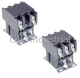
ABB BC16-30-10-01
Description
ABB BC16-30-10-01 Contactor 30Amp 3-Pole 24VDC
Part Number
BC16-30-10-01
Price
Request Quote
Manufacturer
ABB
Lead Time
Request Quote
Category
PRODUCTS - B
Specifications
Number of Auxiliary Contacts NC
0
Number of Auxiliary Contacts NO
1
Number of Main Contacts NC
0
Number of Main Contacts NO
3
Rated Control Circuit Voltage (Uc)
DC Operation 150 V
Rated Operational Current AC-1 (Ie)
(690V) 40°C 28 A; (690V) 55°C 25 A; (690V) 70°C 23 A
Datasheet

Extracted Text
A-Line Extract from Contactors Product Selector 1000 Overload relays AC 1030.1 Contactors Thermal overload relays Electronic overload relays Low Voltage Products and Systems Contactors Across the line, Type A/AF Overload relays Type TA, E Across the line contactors ..............................................................................1.1 – 1.76 1 Overload relays ..............................................................................................2.1 – 2.29 2 Across the line contactors Selection • General information ..................... .......................................................................................................... 1.1 • A9 – A300, AC operated ....... ........................................................................................................1.2 – 1.3 • AE9 – AE110, DC operated ............. .............................................................................................1.4 – 1.5 • BC9 – BC30, DC operated ... ........................................................................................................1.6 – 1.7 • AF50 – AF750, AC & DC operated ..............................................................................................1.8 – 1.9 • Contactors for ring tongue termination . ............................................................................................... 1.10 • A9 – AF750, AC operated, NEMA rated ............................................................................................. 1.11 • AE9 – AF750, DC operated, NEMA rated ....... .................................................................................... 1.12 • A9 – EK550, AC & DC operated, 4 pole ............................................................................................. 1.13 • AF45 – AF75, AC circuit switching, AC & DC operated, 4 pole ................................. ........................ 1.14 • UA26 – UA110, AC operated .............................................................................................................. 1.15 Accessories • Accessories for A, AF, BC & AE contactors .......... .................................................................. 1.16 – 1.17 • Possible accessory combinations for A contactors ............................................................................ 1.18 • Auxiliary contact block technical data ............ ......................................................................... 1.19 – 1.20 • Surge suppressors ................................................................................................................... 1.21 – 1.22 • Interface relays ........................................................................................................................ 1.23 – 1.24 • Accessories for A, AE & AF contactors ................................................................................... 1.25 – 1.30 • TE5S electronic timer for wye-delta starters ........................................................................... 1.31 – 1.32 • Terminal marking and positioning ..... ...................................................................................... 1.33 – 1.35 Technical data • UL & CSA technical data ......................................................................................................... 1.36 – 1.37 • IEC technical data ................................................. ................................................................... 1.38 – 1.53 • Contactor utilization categories & electrical durability ............................................................ 1.54 – 1.57 • Motor data ............................................................ ................................................................................ 1.58 • Tightening torques ........ ........................................................................................................... 1.59 – 1.60 • Technical terms & definitions .............................................................................................................. 1.61 • Standards & utilization categories ..... ...................................................................................... 1.62 – 1.63 Approximate dimensions ........................................................................................................ 1.64 – 1.76 Thermal overload relays Selection • Description & general information ..... ...........................................................................................2.1 – 2.3 • Selection guide .............................................................................................................. ................2.4 – 2.5 • Type TA, Class 10 ........ ......................................................................................................................... 2.6 • Accessories ................................................................................................................................... 2.7 – 2.8 Technical data • TA25DU – TA450DU ................................................................................................................. 2.9 – 2.11 • Motor protection ............................................ ....................................................................................... 2.12 • Resistance and Joule losses per phase; short circuit protection ................................... .................... 2.13 • Tripping curves .. ................................................................................................................................... 2.14 Approximate dimensions ........................................................................................................ 2.15 – 2.17 Electronic overload relays Selection • Description & catalog number explanation .... ......................................................................... 2.19 – 2.20 • E16DU – E800DU ................................................. ............................................................................... 2.21 • Accessories .......................................................................................................................................... 2.22 Technical data • E16DU – E800DU ................................................. ................................................................... 2.23 – 2.25 • Terms & technical definitions .............................................................................................................. 2.26 Approximate dimensions ........................................................................................................ 2.27 – 2.29 Terms & conditions ABB Inc. terms and conditions govern all sales and shipments of products (including parts and accessories) as set forth in document AC 5020. ABB Inc. terms and conditions are subject to change with or without notice. Low Voltage Products & Systems I AC 1030.1 –12/01 This publication is an extract of the AC 1000 Product Selector, to be released in 2002. Type PSS Table of contents Contactors Item Product category Page No. Item Product category Page No. A H A Contactor mounting configurations A 1.18 Horizontal connection busbars A/AE/AF 1.30 A, AE & AF contactor accessories A/AE/AF 1.28 - 1.30 I A/AE/AF Contactor accessories A/AE/AF 1.25 - 1.26 A9 - A/AE75, AC & DC operated A/AE 1.13 Identification marker A/AE/AF 1.25 A9 - A110, Contactors for ring tongue termination A/AE 1.10 IEC contactor technical data A/AE9 - A/AE/AF110 1.38 - 1.40 A9 - A300, AC operated A 1.2 - 1.3 IEC contactor technical data A/AF145 - AF750 1.42 - 1.43 A9 - AF750, AC operated A/AF 1.11 IEC contactor technical data BC9 - BC30 1.44 - 1.46 Accessories for A, AE & AF contactors A/AE/AF 1.28 - 1.30 IEC contactor technical data A/AE, GA/GAE 1.47 Accessories for A/AE/AF contactors A/AE/AF 1.25 - 1.26 IEC contactor technical data A/AE/AF 1.48 Accessories for A/AF/BC/AE contactors A/AF/BC/AE 1.17 IEC contactor technical data EK 1.49 Accessories for EK contactors EK 1.27 IEC contactor technical data BC9 - BC30 1.50 Accessories, front face mounting A 1.18 Accessories, side mounting A 1.18 IEC contactor technical data EK 1.51 - 1.52 Additional terminal blocks A/AE/AF 1.29 IEC technical data, contactors A9 - A40 1.41 AE9 - AE110, DC operated A 1.4 - 1.5 Interface relays A/BC 1.23 - 1.24 AE9 - AF750, DC operated A/AF 1.12 Interlocks for two horizontally mounted contactors A/AF/BC/AE 1.17 AF45 - AF75, AC circuit switching AF 1.14 Interlocks for two vertically mounted contactors A/AF/BC/AE 1.17 AF50 - AF750, AC & DC operated AF 1.8 - 1.9 L AF50 - AF750, AC circuit switching AF 1.9 Low voltage & low current auxiliary contact blocks A/AF/BC/AE 1.16 Approximate dimensions 1.64 - 1.76 Lug kits, terminal A/AE/AF 1.25 Auxiliary contact block technical data CA5/CA5-11/CC5/CE5 1.19 - 1.20 Auxiliary contact blocks, front mounting A/AF/BC/AE 1.16 M Auxiliary contact blocks, low voltage & low current A/AF/BC/AE 1.16 Mechanical latches A/AE/AF 1.25 Auxiliary contact blocks, standard A/AF/BC/AE 1.16 Motor data 1.58 Auxiliary lead terminals A/AF/BC/AE 1.17 P B Phase to phase connection kits A/AE/AF 1.28 BC9 - BC25, AC & DC operated BC 1.13 Pneumatic timers A/AF/BC/AE 1.17 BC9 - BC30, DC operated BC 1.6 - 1.7 Positioning and terminal marking A/UA 1.34 BC9N00 - BC25N1, DC operated BC 1.12 Positioning and terminal marking - auxiliary contacts CA/CC/CAL/CCL 1.33 Positioning, contactor A 1.18 C Possible accessory combinations A 1.18 Capacitor switching contactors, 3 phase UA 1.15 Catalog number explanation A 1.2 R Catalog number explanation AE 1.4 Relays, interface A/BC 1.23 - 1.24 Catalog number explanation BC 1.6 Reversing connection kits A/AE/AF 1.28 Catalog number explanation AF 1.8 Ring tongue termination contactors A/AE 1.10 Circuit diagrams AF 1.53 Coil voltage selection A/AE/AF 1.26 S Coil voltage selection - EK contactors EK 1.27 Shorting bars A/AE/AF 1.30 Coils A/AE/AF 1.26 Side mounting accessories A 1.18 Coils - EK contactors EK 1.27 Standard auxiliary contact blocks A/AF/BC/AE 1.16 Connection bars, vertical A/AE/AF 1.30 Standards, utilization categories 1.62 - 1.63 Connection busbars, horizontal A/AE/AF 1.30 Surge suppressors A/AE/BC/EK 1.21 - 1.22 Connection kits for phase to phase A/AE/AF 1.28 T Connection kits for reversing contactors A/AE/AF 1.28 Connection kits for wye-delta starters A/AE/AF 1.28 Technical data, auxiliary contact blocks CA5/CA5-11/CC5/CE5 1.19 - 1.20 Contact kits A/AE/AF 1.25 Technical data, contactors, IEC A/AE9 A/AE/AF110 1.38 - 1.40 Contactor accessories A/AF/BC/AE 1.17 Technical data, contactors, IEC A9 - A40 1.41 Contactor positioning A 1.18 Technical data, contactors, IEC A/AF145 AF750 1.42 - 1.43 Contactor technical data, IEC A/AE9 - A/AE/AF110 1.38 - 1.40 Technical data, contactors, IEC BC9 - BC30 1.44 - 1.46 Contactor technical data, IEC A9 - A40 1.41 Technical data, contactors, IEC A/AE, GA/GAE 1.47 Contactor technical data, IEC A/AF145 - AF750 1.42 - 1.43 Technical data, contactors, IEC A/AE/AF 1.48 Contactor technical data, IEC BC9 - BC30 1.44 - 1.46 Technical data, contactors, IEC EK 1.49 Contactor technical data, IEC A/AE, GA/GAE 1.47 Technical data, contactors, IEC BC9 - BC30 1.50 Contactor technical data, IEC A/AE/AF 1.48 Technical data, contactors, IEC EK 1.51 - 1.52 Contactor technical data, IEC BC9 - BC30 1.50 Technical data, contactors, UL & CSA A/AE9 A/AE/AF110 1.36 Contactor technical data, IEC EK 1.51 - 1.52 Technical data, UL & CSA A/AF145 AF750 1.37 Contactor technical data, UL & CSA A/AE9 - A/AE/AF110 1.36 Technical terms & definitions 1.61 Contactor utilization categories & electrical durability A9 - A300 1.54 - 1.57 Terminal blocks, additional A/AE/AF 1.29 Contactors for ring tongue termination A/AE 1.10 Terminal enlargements A/AE/AF 1.29 Terminal extensions A/AE/AF 1.29 D Terminal lug kits A/AE/AF 1.25 Dimensions, approximate A/AE/AF/BC 1.64 - 1.76 Terminal marking and positioning A/UA 1.34 DC switching A/AE/AF/EK 1.47 - 1.49 Terminal marking and positioning - auxiliary contacts CA/CC/CAL/CCL 1.33 Terminal shrouds A/AE/AF 1.29 E Tightening torques A/AF/AE/BC, N/KC 1.59 - 1.60 EK contactor accessories EK 1.27 EK110 - EK1000, AC & DC operated EK 1.13 U Electronic timer for wye-delta starters A 1.31 - 1.32 UA26 - UA110, AC operated UA 1.15 UL & CSA contactor technical data A/AE9 A/AE/AF110 1.36 F UL & CSL technical data A/AF145 AF750 1.37 Front face mounting accessories A 1.18 Front mounting auxiliary contact blocks A/AF/BC/AE 1.16 V Vertical connection bars A/AE/AF 1.30 G General description A/AE/AF/B/BC 1.1 W Wye-delta starter connection kits A/AE/AF 1.28 II Low Voltage Products & Systems AC 1030.1 – 12/01 Table of contents Overload relays Item Product category Page No. A Abstract from IEC 947-4-1 TA 2.1 Abstract from IEC 947-4-1 E 2.19 Accessories TA 2.7 - 2.8 Accessories E 2.22 Application technical data TA 2.3 Approximate dimensions TA 2.15 - 2.17 Approximate dimensions E 2.27 - 2.29 C Catalog number explanation TA 2.2 Catalog number explanation E 2.20 D Dimensions, approximate TA 2.15 - 2.17 Dimensions, approximate E 2.27 - 2.29 F Flat pin terminal blocks TA 2.7 G General description TA 2.1 - 2.3 General description E 2.18 I Installation diagrams TA 2.8 L Lug kits E 2.22 Lug kits, terminal TA 2.7 M Mounting kit for TA450 overload relay TA 2.7 Mounting kits E 2.22 Mounting kits, separate TA 2.7 Mounting kits, separate E 2.22 R Remote tripping coils TA 2.8 S Selection guide, Type TA TA 2.4 - 2.5 Selection, Type TA TA 2.6 Selection, Type E E 2.21 Separate mounting kits TA 2.7 T TA450 overload relay mounting kit TA 2.7 Technical characteristics of auxiliary contacts E 2.24 Technical data TA 2.9 - 2.14 Technical data E 2.23 - 2.26 Terminal block - AWG #8 cable TA 2.7 Terminal blocks, flat pin TA 2.7 Terminal lug kits TA 2.7 Terminal shroud for load side E 2.22 Terminal shrouds TA 2.7 Terms and technical definitions E 2.24 Tripping characteristics E 2.24 Tripping classes TA 2.1 Tripping classes E 2.19 Tripping coils, remote TA 2.8 Tripping curves TA 2.14 Type TA, selection TA 2.6 Type E, selection E 2.21 Low Voltage Products & Systems III AC 1030.1 –12/01 Notes IV Low Voltage Products & Systems AC 1030.1 – 12/01 Across the line contactors 2345678901234567890123456789 2345678901234567890123456789 2345678901234567890123456789 2345678901234567890123456789 2345678901234567890123456789 2345678901234567890123456789 2345678901234567890123456789 2345678901234567890123456789 Across the line contactors 2345678901234567890123456789 2345678901234567890123456789 A9 - AF750 2345678901234567890123456789 2345678901234567890123456789 2345678901234567890123456789 1 2345678901234567890123456789 2345678901234567890123456789 2345678901234567890123456789 2345678901234567890123456789 2345678901234567890123456789 2345678901234567890123456789 2345678901234567890123456789 2345678901234567890123456789 2345678901234567890123456789 2345678901234567890123456789 2345678901234567890123456789 2345678901234567890123456789 2345678901234567890123456789 1 2345678901234567890123456789 2345678901234567890123456789 2345678901234567890123456789 2345678901234567890123456789 2345678901234567890123456789 2345678901234567890123456789 2345678901234567890123456789 2345678901234567890123456789 2345678901234567890123456789 2345678901234567890123456789 2345678901234567890123456789 2345678901234567890123456789 2345678901234567890123456789 2345678901234567890123456789 2345678901234567890123456789 2345678901234567890123456789 2345678901234567890123456789 2345678901234567890123456789 2345678901234567890123456789 2345678901234567890123456789 2345678901234567890123456789 A9 - A110 A145 - AF750 2345678901234567890123456789 • Maximum UL/CSA horsepower ratings according • Maximum UL/CSA horsepower ratings according 2345678901234567890123456789 to UL508 and CSA22.2 No. 14 to UL508 and CSA22.2 No. 14 2345678901234567890123456789 • Includes NEMA sizes 00 - 3 • Includes NEMA sizes 4 - 7 2345678901234567890123456789 • CE mark • CE mark 2345678901234567890123456789 2345678901234567890123456789 • Compact space saving design • 1 NO & 1 NC auxiliary contacts are standard and 2345678901234567890123456789 • Standard auxiliary contact configurations: up to 6 additional auxiliary contacts may be added 2345678901234567890123456789 A9 - A40 1 NO or 1 NC to provide a total of 8 (4 NO & 4 NC) 2345678901234567890123456789 A50 - A110 1 NO & 1 NC • Contactors ensure positive safety between their 2345678901234567890123456789 • Contactor sizes A50 - A110 can be supplied auxiliary contact blocks. 2345678901234567890123456789 without auxiliaries • D.C. ratings and D.C. control operation available 2345678901234567890123456789 • Additional auxiliary contact blocks are available • Easy maintenance of main contacts and coil 2345678901234567890123456789 • D.C. ratings & D.C. control operation available inspection 2345678901234567890123456789 • Fast, snap-on DIN rail mounting • Can be mounted in any position 2345678901234567890123456789 • Double break contact design • Operates over an extended voltage range of 85% 2345678901234567890123456789 • Snap-on front mounted accessories include to 110% of rated control voltage 2345678901234567890123456789 2345678901234567890123456789 mechanical latch, pneumatic timer, and 1 & 4 • NEMA, UL, IEC, CSA, VDE and most other 2345678901234567890123456789 pole auxiliary contact blocks international standards 2345678901234567890123456789 • Contactors ensure positive safety between their • UL File No: E79416 2345678901234567890123456789 auxiliary contact blocks. • CSA File No: LR19700 2345678901234567890123456789 • Easy coil change 2345678901234567890123456789 • Captive terminal screws 2345678901234567890123456789 • NEMA, UL, IEC, CSA, VDE and most other 2345678901234567890123456789 international standards 2345678901234567890123456789 • Touch safe design: All connection terminals are 2345678901234567890123456789 protected against accidental touch 2345678901234567890123456789 2345678901234567890123456789 • Terminals supplied open for ease of wiring 2345678901234567890123456789 • Operates over an extended voltage range of 85% 2345678901234567890123456789 to 110% of rated control voltage 2345678901234567890123456789 • Screwdriver guide holes 2345678901234567890123456789 • UL File No: E39231 (A9 - A75); (AE9 - AE75); 2345678901234567890123456789 (BC9 - BC30); (AF50 - AF75) 2345678901234567890123456789 • UL File No: E79416 (A95 - A110); 2345678901234567890123456789 (AE95 - AE110); (AF145 - AF750) 2345678901234567890123456789 • CSA File No: LR56745 (A9 - A75); (AE9 - AE75); 2345678901234567890123456789 (B9 - BC30); (AF50 - AF75) 2345678901234567890123456789 2345678901234567890123456789 • CSA File No: LR19700 (A95 - A110); 2345678901234567890123456789 (AE95 - AE110); (AF145 - AF750) 2345678901234567890123456789 • CSA approved for elevator service 2345678901234567890123456789 2345678901234567890123456789 2345678901234567890123456789 2345678901234567890123456789 2345678901234567890123456789 2345678901234567890123456789 2345678901234567890123456789 2345678901234567890123456789 2345678901234567890123456789 2345678901234567890123456789 2345678901234567890123456789 Low Voltage Products & Systems 1.1 AC 1030.1 - 12/01 Across the line Contactors A9 - A300, AC operated UL rated, 3 pole 1 Application Control circuit types A-Line contactors are mainly used for controlling 3-phase motors and for • A-Line types: AC operated with laminated magnetic circuit. controlling power circuits corresponding to their operating characteristics up to Contactor types 690 and even 1000 VAC. and 440 VDC. • 3 pole contactors with NO or NC built in auxiliary contact for A9 - A40 Description of 3 pole and 4 pole contactors A9 - A300 contactors; factory assembled auxiliary contacts for A50 - A300 contactors All A-Line contactors can be assembled side by side. The add-on or built-in • 4 pole contactors: 4 NO or 2 NO & 2 NC without any auxiliary contacts. auxiliary contacts are suitable for low level currents. (A9 - A75) 1 Quick mounting on DIN rail: EN 50022 and EN 50023 standards: Location of surge suppressors. 35 x 7.5 mm for A9 - A40 35 x 15 mm for A9 - A75 Clear marking of coil voltages and frequencies. 75 mm for A45 - A110 Connecting point for control leads in top part of Location of side mounted accessories: on right or main terminals of A50 - A75 contactors. For A95 left hand side. Factory mounted on left hand side & A110 contactors these are additional power for CAL5 on A50 - A300 connections. Holes for screw mounting (screws not supplied). Terminal marking according to IEC 947-4-1, Distance between holes according to EN 50005, EN 50012 and NEMA standards. EN 50003. Location of function marker. Terminals delivered in open position with captive screws (screws of unused terminals must be tightened). Stops for attaching front mounted accessories. Screwdriver guidance for all terminals makes it possible to use motorized screwdrivers. All terminals provide protection against accidental A9 - A300 Terminal screws: direct contact with live parts according to VDE0106 - Part. 100. • Posidrive (+,-) No 2 for all A9 - A75 All A9 - A40 contactor terminals as well as • M8 hex threaded socket screw for A95 - A300 A45 - A300 contactor auxiliary contact and coil main terminals. terminals ensure IP20 degree of protection according to IEC 947-1. Catalog number explanation A9-30-10-84 Frame size Coil voltage (see coil voltage selection chart) Power pole Auxiliary contacts 30 = 3 NO 40 = 4 NO 10 = 1 NO & 0 NC 22 = 2 NO & 2 NC 01 = 0 NO & 1 NC 11 = 1 NO & 1 NC 00 = No auxiliary provided 22 = 2 NO & 2 NC Coil voltage selection chart Cntr Volts Hz type 12 24 48 110 120 125 208 220 240 277 380 415 440 480 500 600 60 A 81 83 8484 343680 42 8686 5153 55 50 A 81 83 84 80 85 86 55 For other voltages, see page 1.26. 1.2 Low Voltage Products & Systems AC 1030.1 - 12/01 Across the line contactors Across the line contactors A9 - A300, AC operated UL rated, 3 pole 1 1 A26-30-10-84 A110M-30-11-84 A110R-30-11-84 Maximum motor Standard Non-reversing Mechanically interlocked Reversing General UL motor R horsepower ratings Aux. contacts purpose switching Catalog List Catalog List Catalog List current current 208V 240V 480V 575/600V NO NC number price number price number price AC1 UL rated 1 0 A9-30-10-84 A9M-30-10-84 A9R-30-10-84 21 9 2 2 5 7.5 $ 78 $ 255 $ 315 0 1 A9-30-01-84 A9M-30-01-84 A9R-30-01-84 1 0 A12-30-10-84 A12M-30-10-84 A12R-30-10-84 25 11 3 3 7.5 10 84 315 375 0 1 A12-30-01-84 A12M-30-01-84 A12R-30-01-84 1 0 A16-30-10-84 A16M-30-10-84 A16R-30-10-84 30 17 5 5 10 15 102 345 413 0 1 A16-30-01-84 A16M-30-01-84 A16R-30-01-84 1 0 A26-30-10-84 A26M-30-10-84 A26R-30-10-84 40 28 7.5 10 20 25 183 405 480 0 1 A26-30-01-84 A26M-30-01-84 A26R-30-01-84 1 0 A30-30-10-84 A30M-30-10-84 A30R-30-10-84 50 34 10 10 25 30 252 548 623 0 1 A30-30-01-84 A30M-30-01-84 A30R-30-01-84 1 0 A40-30-10-84 A40M-30-10-84 A40R-30-10-84 60 42 10 15 30 40 297 639 750 0 1 A40-30-01-84 A40M-30-01-84 A40R-30-01-84 80 54 15 20 40 50 1 1 A50-30-11-84 330 A50M-30-11-84 713 A50R-30-11-84 810 90 65 20 25 50 60 1 1 A63-30-11-84 372 A63M-30-11-84 870 A63R-30-11-84 1013 105 80 25 30 60 75 1 1 A75-30-11-84 413 A75M-30-11-84 1155 A75R-30-11-84 1298 125 95 30 30 60 75 1 1 A95-30-11-84 450 A95M-30-11-84 1230 A95R-30-11-84 1425 140 110 30 40 75 100 1 1 A110-30-11-84 480 A110M-30-11-84 1365 A110R-30-11-84 1628 230 130 40 50 100 125 1 1 A145-30-11-84 825 A145M-30-11-84 2235 A145R-30-11-84 2250 250 156 50 60 125 150 1 1 A185-30-11-84 1290 A185M-30-11-84 3360 A185R-30-11-84 3375 300 192 60 75 150 200 1 1 A210-30-11-84 1635 A210M-30-11-84 4035 A210R-30-11-84 4050 350 248 75 100 200 250 1 1 A260-30-11-84 1815 A260M-30-11-84 4485 A260R-30-11-84 4500 400 302 100 100 250 300 1 1 A300-30-11-84 1875 A300M-30-11-84 5460 A300R-30-11-84 5475 550 414 125 150 350 400 1 1 650 480 150 200 400 500 1 1 See Type AF contactors, page 1.9 750 590 200 250 500 600 1 1 900 720 250 300 600 700 1 1 Coil voltage selection Coil voltage selection chart Volts All AC operated catalog numbers include a 120VAC coil. To select other coil Cntr Hz type 12 24 48 110 120 125 208 220 240 277 380 415 440 480 500 600 voltages, substitute the code from the Coil Voltage Selection Chart for the two 60 A 81 838484 34 368042 86 86 51 53 55 digits after the last dash in the catalog number. 50 A 81 8384 80 8586 55 Ex.: A 240V coil is required for an A75 contactor: A75-30-11-80 For other voltages, see page 1.26. Auxiliary contact blocks Reversing For additional auxiliary contact blocks, see catalog number explanation on page Reversing contactors are designed for reversing type starter applications. The 1.2. Add $ 20 to list price for each additional auxiliary, and see page 1.18 for complete assembly consists of two mechanically and electrically interlocked available combinations. Only side-mounted blocks are allowed to be factory contactors mounted as follows with line and load terminals: installed. If auxiliary contacts are not required for A50 - A300, subtract $ 40 from list price and change catalog number to “00” instead of “11.” • A9 - A16 — mounted on 35 mm DIN rail • A26 - A300 — mounted on common baseplate Mechanical interlock The NC electrical interlock is provided with the mechanical interlock for A9 - Mechanically interlocked contactors are designed for reversing, 2 speed, A110 contactors. reduced voltage, etc. type starter applications. The complete assembly consists of two mechanically and electrically interlocked contactors mounted as follows with line and load terminals: • A9 - A16 — mounted on 35mm DIN rail • A26 - A300 — mounted on common baseplate Power wiring is not included. The NC electrical interlock is provided with the mechanical interlock for A9 - A110 contactors. Discount schedule AA - A9 - A110 Low Voltage Products & Systems 1.3 Discount schedule AEA - A145 - A300 AC 1030.1 - 12/01 AE9 - AE110, DC operated UL rated, 3 pole 1 Uc (DC) Application Uc (DC) A-Line contactors are mainly used for controlling 3-phase motors and for CDL5 (AE45 to AE75) A1 A2 controlling power circuits corresponding to their operating characteristics up to CCL5 (AE95 to AE110) A1 A2 B2 - Holding 690 and even 1000 VAC. and 440 VDC. NC contact in B2 - Holding Control circuit types 4th contactor pole AE types: with laminated magnetic circuit and double-winding coil fed from DC supply via a CDL5 insertion contact mounted on the device. The CDL5 has an B1 - Pull-in NC lagging contact for insertion of the second winding. (See schematic.) 1 A3 B1 - Pull-in A3 AE9 to AE40 AE45 to AE110 Location of surge suppressors. Quick mounting on DIN rail: EN 50022 and EN 50023 standards: Clear marking of coil voltages and frequencies. 35 x 7.5 mm for AE9 - AE40 35 x 15 mm for AE9 - AE75 Connecting point for control leads in top part of 75 mm for AE45 - AE110 main terminals of AE50 - AE75 contactors. For AE95 & AE110 contactors these are additional Location of side mounted accessories: on right power connections. or left hand side. Factory mounted on left hand side for CAL5 on A50 - A300 Terminal marking according to IEC 947-4-1, • right hand side for CDL5/CCL5 on EN 50005, EN 50012 and NEMA standards. AE45 - AE110 Location of function marker. Holes for screw mounting (screws not supplied). Distance between holes according to EN 50003. Stops for attaching front mounted accessories. Terminal screws: Terminals delivered in open position with captive AE9 - AE110 • Posidrive (+,-) No° 2 for all AE9 - AE75 screws (unused terminal screws must be • M8 hex threaded socket screw for AE95 & AE110 tightened). Screwdriver guidance for all terminals makes it possible to use motorized screwdrivers. All terminals provide protection against accidental direct contact with live parts according to VDE0106 - Part. 100. All AE9 - AE40 contactor terminals as well as AE45 - AE110 contactor auxiliary contact and coil terminals ensure IP20 degree of protection according to IEC 947-1. Catalog number explanation AE9-30-00-81 Frame size Coil voltage (see coil voltage selection chart) Power pole Auxiliary contacts 30 = 3 NO 40 = 4 NO 00 = No auxiliary provided 22 = 2 NO & 2 NC 11 = 1 NO & 1 NC Coil voltage selection chart Volts Contr. Hz type 12 24 48 110 125 220 240 DC AE 80 81 83 86 87 88 89 For other voltages, see page 1.26. 1.4 Low Voltage Products & Systems AC 1030.1 - 12/01 Across the line contactors Varistor U Across the line contactors AE9 - AE110, DC operated UL rated, 3 pole 1 1 AE26-30-11-81 AE110M-30-11-81 AE110R-30-11-81 Maximum motor Standard Non-reversing Mechanically interlocked Reversing General UL motor R horsepower ratings Aux. contacts purpose switching Catalog List Catalog List Catalog List current current 208V 240V 480V 57 5/600V NO NC number price number price number price AC1 UL rated 21 9 2 2 5 7.5 1 1 AE9-30-11-81 118 AE9M-30-11-81 335 AE9R-30-11-81 395 25 11 3 3 7.5 10 1 1 AE12-30-11-81 124 AE12M-30-11-81 395 AE12R-30-11-81 455 30 17 5 5 10 15 1 1 AE16-30-11-81 142 AE16M-30-11-81 425 AE16R-30-11-81 493 40 28 7.5 10 20 25 1 1 AE26-30-11-81 223 AE26M-30-11-81 485 AE26R-30-11-81 560 50 34 10 10 25 30 1 1 AE30-30-11-81 292 AE30M-30-11-81 628 AE30R-30-11-81 703 60 42 10 15 30 40 1 1 AE40-30-11-81 337 AE40M-30-11-81 719 AE40R-30-11-81 830 80 54 15 20 40 50 1 1 AE50-30-11-81 375 AE50M-30-11-81 803 AE50R-30-11-81 930 90 65 20 25 50 60 1 1 AE63-30-11-81 477 AE63M-30-11-81 1080 AE63R-30-11-81 1200 105 80 25 30 60 75 1 1 AE75-30-11-81 518 AE75M-30-11-81 1365 AE75R-30-11-81 1493 125 95 30 30 60 75 1 1 AE95-30-11-81 555 AE95M-30-11-81 1440 AE95R-30-11-81 1635 140 110 30 40 75 100 1 1 AE110-30-11-81 690 AE110M-30-11-81 1785 AE110R-30-11-81 2048 230 130 40 50 100 125 1 1 250 156 50 60 125 150 1 1 300 192 60 75 150 200 1 1 350 248 75 100 200 250 1 1 See AF contactors, page 1.9 400 302 100 100 250 300 1 1 550 414 125 150 350 400 1 1 650 480 150 200 400 500 1 1 750 590 200 250 500 600 1 1 900 720 250 300 600 700 1 1 Coil voltage selection Coil voltage selection chart Volts All DC operated catalog numbers include a 24VDC coil. To select other coil Contr. Hz voltages, substitute the code from the Coil Voltage Selection Chart for the two type 12 24 48 110 125 220 240 digits after the last dash in the catalog number. DC AE 80 81 83 86 87 88 89 Ex.: A 110V coil is required for an AE75 contactor: AE75-30-11- 86 For other voltages, see page 1.26. Auxiliary contact blocks Reversing For additional auxiliary contact blocks, see catalog number explanation on page Reversing contactors are designed for reversing type starter applications. The 1.4. Add $ 20 to list price for each additional auxiliary, and see page 1.18 for complete assembly consists of two mechanically and electrically interlocked available combinations. contactors mounted as follows with line and load terminals: Mechanical interlock • AE9 - AE16 — mounted on 35 mm DIN rail Mechanically interlocked contactors are designed for reversing, 2 speed, • AE26 - AE110 — mounted on common baseplate reduced voltage, etc. type starter applications. The complete assembly consists The NC electrical interlock is provided with the mechanical interlock. of two mechanically and electrically interlocked ocntactors mounted as follows with line and load terminals: • AE9 - AE16 — mounted on 35mm DIN rail • AE26 - AE110 — mounted on common baseplate Power wiring is not included. The NC electrical interlock is provided with the mechanical interlock. Low Voltage Products & Systems Discount schedule AA - AE9 - AE110 1.5 AC 1030.1 - 12/01 BC9 - BC30, DC operated UL rated, 3 pole 1 Application Type of magnetic circuit Type BC contactors are used for controlling 3 phase motors and for controlling • Solid magnetic circuit with DC powered coil. power circuits corresponding to their operating characteristics up to 690 VAC Contact types and 440 VDC. • 3 pole contactors with built in NO or NC auxiliary contact for Description BC9 - BC30 contactors. For BC type contactors, make sure that the mounting distance is maintained as • 4 pole contactors: 4 NO or 2 NO & 2 NC without any auxiliary contacts. described below. Contactors for specific applications The add-on or built in auxiliary contacts are suitable for low level currents. 1 • DC operated TBC-types with large voltage range specific to the traction Mounting distance industry. A B Ambient temperature Max. switching frequency dim dim °C operating cycles/hr 2 20 ≤20 1200 5 20 ≤55 1200 A ABB ABB Pos. 3 / Pos. 4 Pos. 1, 2, 5, 6 Quick mounting on mounting rail according to IEC Dove tail anchoring for surge suppressor 715 and EN 50022 standards: assembly. • 35 x 7.5mm • 35 x 15mm Clear marking of coil DC voltage. Terminal screw types: • Posidrive (+,-) No 2; M3.5 for all BC9 and BC16 Terminal marking according to IEC 947-4-1, terminals and BC25 - BC30 coil terminals. EN 50005, EN 50012 and NEMA standards. • Posidrive (+,-) No 2; M4 for BC25 main terminals. Terminals delivered in open position with captive • Posidrive (+,-) No 2; M5 for BC30 main screws (screws of unused terminals must be terminals. tightened). Screwdriver guidance for all terminals makes it possible to use motorized screwdrivers. Holes for screw mounting (screws not supplied). All terminals provide protection against accidental Distance between holes according to EN 50003. direct contact with live parts according to VDE0106-Part. 100. BC9 - BC30 Stops for attaching front mounted accessories. Location of function marker. Catalog number explanation BC9-30-10-01 Frame size Coil voltage (see coil voltage selection chart) Power pole 30 = 3 NO Auxiliary contacts 40 = 4 NO 10 = 1 NO & 0 NC 22 = 2 NO & 2 NC 01 = 0 NO & 1 NC Coil voltage selection chart Cntr Volts Hz type 12 24 48 110 120 125 208 220 240 DC BC 07 01 16 04 27 05 33 For other voltages, see page 1.26. 1.6 Low Voltage Products & Systems AC 1030.1 - 12/01 V DC 220 5L3 1L1 5- A1 3L2 4- 13 3- BC9-30-10 2- 2- 5- 3- 4T2 4- 14 2T1 6T3 Across the line contactors B ABB ABB Across the line contactors BC9 - BC30, DC operated UL rated, 3 pole 1 1 BC16-30-10-01 BC25-30-01-04 BC Contactors Maximum motor Standard General UL motor Non-reversing Mechanically interlocked Reversing R horsepower ratings Aux. contacts purpose switching Catalog List Catalog List Catalog List current current 208V 240V 480V 57 5/600V NO NC number price number price number price AC1 UL rated 1 0 BC9-30-10-01 BC9M-30-10-01 BC9R-30-10-01 $ 123 $ 345 $ 405 21 9 2 2 5 7.5 0 1 BC9-30-01-01 BC9M-30-01-01 BC9R-30-01-01 1 0 BC16-30-10-01 BC16M-30-10-01 BC16R-30-10-01 147 435 503 30 17 5 5 10 15 0 1 BC16-30-01-01 BC16M-30-01-01 BC16R-30-01-01 1 0 BC25-30-10-01 BC25M-30-10-01 BC25R-30-10-01 40 28 7.5 10 20 25 228 495 570 0 1 BC25-30-01-01 BC25M-30-01-01 BC25R-30-01-01 1 0 BC30-30-00-01 267 BC30M-30-10-01 BC30R-30-10-01 668 743 50 34 10 10 20 30 0 1 BC30-30-22-01 297 BC30M-30-01-01 BC30R-30-01-01 Coil voltage selection Mechanical interlock All DC operated catalog numbers include a 24VDC coil. To select other coil Mechanically interlocked contactors are designed for reversing, 2 speed, voltages, substitute the code from the Coil Voltage Selection Chart for the two reduced voltage, etc. type starter applications. The complete assembly consists digits after the last dash in the catalog number. of two mechanically and electrically interlocked contactors mounted as follows with line and load terminals: Ex.: A 220V coil is required for an BC30 contactor: BC30-30-10-05 • BC9 & BC16 — mounted on 35mm DIN rail Auxiliary contact blocks • BC25 & BC30 — mounted on common baseplate For additional auxiliary contact blocks, see catalog number explanation on page Power wiring is not included. 1.6. Add $ 20 to list price for each additional auxiliary, and see page 1.18 for The NC electrical interlock is provided available combinations. Reversing Coil voltage selection chart Reversing contactors are designed for reversing type starter applications. The Cntr Volts Hz complete assembly consists of two mechanically and electrically interlocked type 12 24 48 110 120 125 208 220 240 contactors mounted with line and load terminals. DC BC 07 01 16 04 27 05 33 For other voltages, see page 1.26. Low Voltage Products & Systems Discount schedule AA - BC9 - BC30 1.7 AC 1030.1 - 12/01 AF50 - AF750, AC & DC operated UL rated, 3 pole 1 Application Control circuit types A-Line contactors are mainly used for controlling 3-phase motors and • AF types: AC/DC operated with laminated magnetic circuit. for controlling power circuits corresponding to their operating Contact or types characteristics up to 690 and even 1000 VAC. and 440 VDC. • 3 pole contactors with 1 NO or 1 NC factory assembled auxiliary Description of 3 pole contactors AF50 - AF750 contacts for AF50 - AF750 contactors All AF contactors can be assembled side by side. The add-on auxiliary contacts are suitable for low level currents. 1 Quick mounting on DIN rail: EN 50022 and EN 50023 standards: Surge suppressors built in as standard on the printed circuit board. 35 x 15 mm for AF50 - AF75 75 mm for AF50 - AF110 Clear marking of coil voltages and frequencies. Connecting point for control leads in top part of Location of side mounted accessories: on right or main terminals of AF50 - AF75 contactors. For left hand side. Factory mounted on left hand side AF95 & AF110 contactors these are additional for CAL5 on AF50 - AF750 power connections. Holes for screw mounting (screws not supplied). Terminal marking according to IEC 947-4-1, Distance between holes according to EN 50005, EN 50012 and NEMA standards. EN 50003. Location of function marker. Stops for attaching front mounted accessories. Terminals delivered in open position with captive Terminal screws: screws (screws of unused terminals must be • Posidrive (+,-) No 2 for all AF50 – AF75 tightened). AF50 - AF750 • M8 hex threaded socket screw for AF95 – Screwdriver guidance for all terminals makes it AF750 main terminals. possible to use motorized screwdrivers. All terminals provide protection against accidental direct contact with live parts according to VDE0106 - Part. 100. All AF50- AF110 contactor terminals as well as AF50 - AF750 contactor auxiliary contact and coil terminals ensure IP20 degree of protection according to IEC 947-1. Catalog number explanation AF50- 30-11-70 Frame size Coil voltage (see coil voltage selection chart) Power pole Auxiliary contacts 30 = 3 NO 40 = 4 NO 11 = 1 NO & 1 NC 22 = 2 NO & 2 NC 00 = No auxiliary provided 22 = 2 NO & 2 NC Coil voltage selection – AF50 to AF750 AC/DC VOLTS, 40 - 60 HZ 24 - 60 DC 20 - 60 DC 48 - 130 AC/DC 100 - 250 AC/DC 200 - 500 AC/DC 68 1 72 2 69 3 70 71 3 1 AF400 – AF750, DC only. 2 AF50 – AF300, DC only. 3 Available 4th quarter, 2001. 1.8 Low Voltage Products & Systems AC 1030.1 - 12/01 A1 A2 1 L1 3 L2 5 L3 U L Across the line contactors Across the line contactors AF50 - AF750, AC circuit switching AC & DC operated UL rated, 3 pole 1 1 AF63-30-11-70 AF95-30-11-70 AF400-30-11-70 AF750-30-11-70 3 Pole General UL motor Standard Non-reversing Mechanically interlocked Reversing purpose switching Maximum UL Listed auxiliary Catalog List Catalog List Catalog List current current motor horsepower ratings contacts number price number price number price AC1 208V 240V 480V 575/600V NO NC 80 54 15 20 40 50 1 1 AF50-30-11-70 $ 450 AF50M-30-11-70 $ 953 AF50R-30-11-70 $ 1050 90 65 20 25 50 60 1 1 AF63-30-11-70 495 AF63M-30-11-70 1116 AF63R-30-11-70 1259 105 80 25 30 60 75 1 1 AF75-30-11-70 535 AF75M-30-11-70 1399 AF75R-30-11-70 1542 125 95 30 30 60 75 1 1 AF95-30-11-70 570 AF95M-30-11-70 1470 AF95R-30-11-70 1665 140 110 30 40 75 100 1 1 AF110-30-11-70 600 AF110M-30-11-70 1605 AF110R-30-11-70 1868 230 130 40 50 100 125 1 1 AF145-30-11-70 1110 AF145M-30-11-70 2655 AF145R-30-11-70 2670 250 156 50 60 125 150 1 1 AF185-30-11-70 1635 AF185M-30-11-70 3870 AF185R-30-11-70 3885 300 192 60 75 150 200 1 1 AF210-30-11-70 1980 AF210M-30-11-70 4545 AF210R-30-11-70 4560 350 248 75 100 200 250 1 1 AF260-30-11-70 2235 AF260M-30-11-70 5055 AF260R-30-11-70 5070 400 302 100 100 250 300 1 1 AF300-30-11-70 2385 AF300M-30-11-70 6030 AF300R-30-11-70 6045 550 414 125 150 350 400 1 1 AF400-30-11-70 3120 AF400M-30-11-70 6705 AF400R-30-11-70 6720 650 480 150 200 400 500 1 1 AF460-30-11-70 4425 AF460M-30-11-70 13,275 AF460R-30-11-70 13,290 750 590 200 250 500 600 1 1 AF580-30-11-70 6900 AF580M-30-11-70 18,375 AF580R-30-11-70 18,390 900 720 250 300 600 700 1 1 AF750-30-11-70 7200 AF750M-30-11-70 19,725 AF750R-30-11-70 19,740 Coil voltage selection – wide range AC/DC coils All catalog numbers include a 100-250V AC/DC coil. To select other coil voltages, substitute the code from the Coil Voltage Selection Chart for the two digits after the last dash in the catalog number. Ex.: A 24V coil is required for a AF110 contactor: AF110-30-11- 68 Coil voltage selection – AF50 to AF750 AC/DC VOLTS, 40 - 60 HZ 24 - 60 DC 20 - 60 DC 48 - 130 AC/DC 100 - 250 AC/DC 200 - 500 AC/DC 68 1 72 2 69 3 70 71 3 1 AF400 – AF750, DC only. 2 AF50 – AF300, DC only. 3 Available 4th quarter, 2001. Low Voltage Products & Systems Discount schedule AA - AF50 – AF110 1.9 Discount schedule AEA - AF145 - AF750 AC 1030.1 - 12/01 Contactors for ring tongue termination A/E9 - A/AE110, AC & DC operated 1 UL rated, 3 pole AC Motor UL/CSA horsepower ratings Auxiliary contacts AC operated DC operated circuit switching switching current 240V 480V 575/600V NO NC Catalog List Catalog List AC1 AC3 number price number price 1 0 A93010RT-84 AE93010RT-81 21 9 2 5 7.5 $ 81 $ 91 0 1 A93001RT-84 AE93001RT-81 1 0 A123010RT-84 AE123010RT-81 25 11 3 7.5 10 87 97 0 1 A123001RT-84 AE123001RT-81 1 0 A163010RT-84 AE163010RT-81 30 17 5 10 15 106 116 1 0 1 A163001RT-84 AE163001RT-81 1 0 A263010RT-84 AE263010RT-81 40 28 10 20 25 189 199 0 1 A263001RT-84 AE263001RT-81 80 54 20 40 50 0 0 A503000RT-84 311 AE503000RT-81 356 90 65 25 50 60 0 0 A633000RT-84 354 AE633000RT-81 459 105 80 30 60 75 0 0 A753000RT-84 396 AE753000RT-81 501 125 95 30 60 75 0 0 A953000RT-84 466 AE953000RT-81 571 140 110 40 75 100 0 0 A1103000RT-84 543 AE1103000RT-81 753 Coil voltage selection – AC coils Coil voltage selection chart – AC coils Volts All AC operated catalog numbers include a 120VAC coil. To select other coil Cntr Hz type 12 24 48 110 120 125 208 220 240 277 380 415 440 480 500 600 voltages, substitute the code from the AC coils Coil Voltage Selection Chart for 60 A 81838484 343680 42 8686 51 53 55 the two digits after the last dash in the catalog number. 50 A 818384 80 8586 55 Ex.: A 240V coil is required for an A75 contactor: A753000RT-80 For other voltages, see page 1.26. Coil voltage selection – DC coils Coil voltage selection chart – DC coils All DC operated catalog numbers include a 24VDC coil. To select other coil voltages, substitute the code from the DC coils Coil Voltage Selection Chart for Volts Contr. Hz the two digits after the last dash in the catalog number. type 24 48 110 125 220 240 Ex.: A 110V coil is required for an AE75 contactor: AE753000RT-86 DC AE 81 83 86 87 88 89 Auxiliary contact blocks For other voltages, see page 1.26. For additional auxiliary contact blocks, see catalog number explanation on page 1.2. Add $ 20 to list price for each additional auxiliary, and see page 1.18 for available combinations. Only side-mounted blocks are allowed to be factory installed. Auxiliary contact block with ring tongue termination Maximum number Contact Catalog List Positioning of contact blocks description number price 2 NO & 2 NC CA5-22ERT Front mounting 1 block 3 NO & 1 NC CA5-31ERT $ 35 (C4-pole) A9 – A110 4 NO CA5-40ERT 1.10 Discount schedule AA - A9 - A110 Low Voltage Products & Systems AC 1030.1 - 12/01 Across the line contactors Across the line contactors A9 – AF750, AC operated NEMA rated, 3 pole 1 1 A26N1-30-10-84 A145N4-30-11-84 AF400N6-30-11-70 Maximum motor Standard Non-reversing Mechanically interlocked Reversing R horsepower ratings Aux. contacts NEMA Continuous Catalog List Catalog List Catalog List size current 200V 230V 46 0/575V NO NC number price number price number price NEMA rated 00 9 1.5 1.5 2 1 0 A9N00-30-10-84 $ 78 A9N00M-10-84 $ 255 A9N00R-10-84 $ 315 0 18 3 3 5 1 0 A16N0-30-10-84 102 A16N0M-10-84 345 A16N0R-10-84 413 1 27 7.5 7.5 10 1 0 A26N1-30-10-84 183 A26N1M-10-84 405 A26N1R-10-84 480 2 45 10 15 25 1 1 A50N2-30-11-84 330 A50N2M-11-84 713 A50N2R-11-84 810 3 90 25 30 50 1 1 A75N3-30-11-84 413 A75N3M-11-84 1155 A75N3R-11-84 1298 4 135 40 50 100 1 1 A145N4-30-11-84 825 A145N4M-11-84 2235 A145N4R-11-84 2250 5 270 75 100 200 1 1 A260N5-30-11-84 1815 A260N5M-11-84 4485 A260N5R-11-84 4500 6 540 150 200 400 1 1 AF460N6-3011-70 4425 AF460N6M-11-70 13,275 AF460N6R-11-70 13,290 7 810 — 300 600 1 1 AF750N7-3011-70 7200 AF750N7M-11-70 19,725 AF750N7R-11-70 19,740 Coil voltage selection – A contactors Reversing All AC operated catalog numbers include a 120VAC coil. To select other coil Reversing contactors are designed for reversing type starter applications. The voltages, substitute the code from the Coil Voltage Selection Chart for the two complete assembly consists of two mechanically and electrically interlocked digits after the last dash in the catalog number. contactors mounted as follows with line and load terminals: Ex.: A 240V coil is required for an A75 contactor: A75-30-11- 80 • A9 - A16 — mounted on 35mm DIN rail • A26 - A750 — mounted on common baseplate Coil voltage selection – wide range AC/DC coils For A9 - A750 contactors the NC electrical interlock is provided with the All catalog numbers include a 100-250V AC/DC coil. To select other coil mechanical interlock. voltages, substitute the code from the Coil Voltage Selection Chart for the two digits after the last dash in the catalog number. Coil voltage selection chart – A contactors Ex.: A 24V coil is required for a AF145 contactor: AF145N4-30-11- 68 Cntr Volts Hz type 12 24 48 110 120 125 208 220 240 277 380 415 440 480 500 600 Auxiliary contact blocks 60 A 81838484 34 368042 8686 5153 55 For additional auxiliary contact blocks, see catalog number explanation on page 50 A 818384 80 8586 55 1.2. Add $ 20 to list price for each additional auxiliary, and see page 1.18 for For other voltages, see page 1.26. available combinations. Coil voltage selection – AF50 to AF750 Mechanical interlock AC/DC VOLTS, 40 - 60 HZ Mechanically interlocked contactors are designed for reversing, 2 speed, reduced voltage, etc. type starter applications. The complete assembly consists 24 - 60 DC 20 - 60 DC 48 - 130 AC/DC 100 - 250 AC/DC 200 - 500 AC/DC of two mechanically and electrically interlocked contactors mounted as follows 68 1 72 2 69 3 70 71 3 with line and load terminals: • A9 - A16 — mounted on 35mm DIN rail • A26 - A750 — mounted on common baseplate Power wiring is not included. For A9 - A110 contactors the NC electrical interlock is provided with the mechanical interlock. 1 AF400 – AF750, DC only. 2 AF50 – AF300, DC only. 3 Available 4th quarter, 2001. Low Voltage Products & Systems 1.11 Discount schedule AA - A9 - A110 Discount schedule AEA - A145 - AF750 AC 1030.1 - 12/01 AE9 – AF750, DC operated BC9 – BC25, DC operated 1 NEMA rated, 3 pole 1 AE26N1-30-11-81 AF145N4-30-11-68 AF460N6R-11-68 AE & AF Contactors Maximum motor Standard Non-reversing Mechanically interlocked Reversing R horsepower ratings Aux. contacts NEMA Continuous Catalog List Catalog List Catalog List size current 200V 230V 460/575V NO NC number price number price number price NEMA rated 00 9 1.5 1.5 2 1 0 AE9N00-30-11-81 $ 118 AE9N00M-11-81 $ 335 AE9N00R-11-81 $ 395 0 18 3 3 5 1 0 AE16N0-30-11-81 142 AE16N0M-11-81 425 AE16N0R-11-81 493 1 27 7.5 7.5 10 1 0 AE26N1-30-11-81 223 AE26N1M-11-81 485 AE26N1R-11-81 560 2 45 10 15 25 1 1 AE50N2-30-11-81 375 AE50N2M-11-81 803 AE50N2R-11-81 930 3 90 25 30 50 1 1 AE75N3-30-11-81 518 AE75N3M-11-81 1365 AE75N3R-11-81 1493 4 135 40 50 100 1 1 AF145N4-3011-68 1110 AF145N4M-11-68 2655 AF145N4R-11-68 2670 5 270 75 100 200 1 1 AF260N5-3011-68 2235 AF260N5M-11-68 5055 AF260N5R-11-68 5070 6 540 150 200 400 1 1 AF460N6-3011-68 4425 AF460N6M-11-68 13,275 AF460N6R-11-68 13,290 7 810 — 300 600 1 1 AF750N7-3011-68 7200 AF750N7M-11-68 19,725 AF750N7R-11-68 19,740 BC Contactors Maximum motor Standard Non-reversing Mechanically interlocked Reversing R horsepower ratings Aux. contacts NEMA Continuous Catalog List Catalog List Catalog List size current 208V 240V 460/575V NO NC number price number price number price NEMA rated 00 9 1.5 1.5 2 1 0 BC9N00-30-10-01 $ 123 BC9N00M-10-01 $ 345 BC9N00R-10-01 $ 405 0 18 3 3 5 1 0 BC16N0-30-10-01 147 BC16N0M-10-01 435 BC16N0R-10-01 503 1 27 7.5 7.5 10 1 0 BC25N1-30-10-01 228 BC25N1M-10-01 495 BC25N1R-10-01 570 Coil voltage selection – A contactors Reversing All AC operated catalog numbers include a 120VAC coil. To select other coil Reversing contactors are designed for reversing type starter applications. The voltages, substitute the code from the Coil Voltage Selection Chart for the two complete assembly consists of two mechanically and electrically interlocked digits after the last dash in the catalog number. contactors mounted as follows with line and load terminals: Ex.: A 240V coil is required for an A75 contactor: A75-30-11- 80 • A9 - A16 — mounted on 35mm DIN rail • A26 - A110 — mounted on common baseplate Coil voltage selection – wide range AC/DC coils For A9 - A110 contactors the NC electrical interlock is provided with the All catalog numbers include a 100-250V AC/DC coil. To select other coil mechanical interlock. voltages, substitute the code from the Coil Voltage Selection Chart for the two digits after the last dash in the catalog number. Coil voltage selection – AF50 to AF750 Ex.: A 24V coil is required for a AF145 contactor: AF145N4-30-11- 68 AC/DC VOLTS, 40 - 60 HZ Auxiliary contact blocks 24 - 60 DC 20 - 60 DC 48 - 130 AC/DC 100 - 250 AC/DC 200 - 500 AC/DC For additional auxiliary contact blocks, see catalog number explanation on page 68 1 72 2 69 3 70 71 3 1.2. Add $ 20 to list price for each additional auxiliary, and see page 1.18 for available combinations. Coil voltage selection chart – BC contactors Mechanical interlock Cntr Volts Hz Mechanically interlocked contactors are designed for reversing, 2 speed, type 12 24 48 110 120 125 208 220 240 reduced voltage, etc. type starter applications. The complete assembly consists DC BC 07 01 16 04 27 05 33 of two mechanically and electrically interlocked contactors mounted as follows with line and load terminals: Coil voltage selection chart – AE contactors • A9 - A16 — mounted on 35mm DIN rail • A26 - A110 — mounted on common baseplate Volts Contr. Hz Power wiring is not included. type 12 24 48 110 125 220 240 For A9 - A110 contactors the NC electrical interlock is provided with the DC AE – 81 838687 88 89 mechanical interlock. DC BC 07 01 16 04 27 05 33 1 AF400 – AF750, DC only. 2 AF50 – AF300, DC only. 3 Available 4th quarter, 2001. 1. 12 Low Voltage Products & Systems Discount schedule AA - A9 - A110 AC 1030.1 - 12/01 Discount schedule AEA - A145 - AF750 Across the line contactors Across the line contactors A9 – A/AE75 , EK110 – EK1000, BC9 – BC25 AC & DC operated UL rated, 4 pole 1 1 A9-40-00 A26-40-00 EK175C4P-PL 4 Pole – 4 NO power poles UL general purpose current AC operated DC operated AC operated DC operated Catalog number List price Catalog number List price 21 21 A9-40-00-84 $ 120 BC9-40-00-04 $ 165 30 21 A16-40-00-84 165 BC16-40-00-04 210 40 30 A26-40-00-84 228 BC25-40-00-04 273 65 65 A45-40-00-84 360 AE45-40-00-86 420 80 80 A50-40-00-84 413 AE50-40-00-86 473 105 105 A75-40-00-84 525 AE75-40-00-86 570 150 150 EK110C4P-1L 743 EK110C4P-PL 953 200 200 EK150C4P-1L 1013 EK150C4P-PL 1238 250 250 EK175C4P-1L 1763 EK175C4P-PL 1988 300 300 EK210C4P-1L 2025 EK210C4P-PL 2280 400 400 EK370C4P-1L 4650 EK370C4P-PL 5010 600 600 EK550C4P-1L 6510 EK550C4P-PL 7005 1000 1 1000 1 EK1000C4P-1L 9000 EK1000C4P-PL 9700 4 Pole – 4 NC power poles UL general purpose current AC operated AC Catalog List operated number price 30 A16-04-00-84 $ 165 4 Pole - 2 NO & 2 NC power poles UL general purpose current AC operated DC operated AC operated DC operated Catalog number List price Catalog number List price 21 21 A9-22-00-84 $ 120 BC9-22-00-04 $ 165 30 21 A16-22-00-84 165 BC16-22-00-04 210 40 30 A26-22-00-84 228 BC25-22-00-04 273 65 65 A45-22-00-84 360 AE45-22-00-04 420 105 105 A75-22-00-84 525 AE75-22-00-04 570 Coil voltage selection chart – A contactors Coil voltage selection Cntr Volts All AC operated catalog numbers include a 120VAC coil. All DC operated Hz type 12 24 48 110 120 125 208 220 240 277 380 415 440 480 500 600 catalog numbers include a 110VDC coil. To select other coil voltages, substitute 60 A 81 838484 34 368042 86 86 51 53 55 the code from the Coil Voltage Selection Chart for the two digits after the last 50 A 81 8384 80 8586 55 dash in the catalog number. For other voltages, see page 1.26. Ex.: A 240V coil is required for an A75 contactor: A75-30-00-80 Auxiliary contact blocks Coil voltage selection chart – EK contactors Volts For additional auxiliary contact blocks, see catalog number explanation on page Contr. Hz type 24 48 110 120 125 208 220 240 277 380 415 440 480 500 600 1.2. Add $ 20 to list price for each additional auxiliary, and see page 1.18 for 60 EK F G 1 B 2 C Z 3 4 6 available combinations. 50 EK N 1 J 3 M 5 Accessories for EK DC EK Y W P Q R T Please consult factory. • For other voltages, consult factory. • 24 & 48VAC coils are not available for sizes EK550. For these applications, use an interposing control relay. Coil voltage selection chart – BC contactors Cntr Volts Hz Coil voltage selection chart – AE contactors type 12 24 48 110 120 125 208 220 240 Volts DC BC 07 01 16 04 27 05 33 Contr. Hz type 12 24 48 110 125 220 240 For other voltages, see page 1.26. DC AE – 81 83 86 87 88 89 For other voltages, see page 1.26. 1 Not UL Listed. IEC value AC1 for 40°C. Low Voltage Products & Systems Discount schedule AA - A9 - A75 1.13 Discount schedule AEA - EK110 - EK550 AC 1030.1 - 12/01 AF45 - AF75, AC circuit switching AC & DC operated 1 UL rated, 4 pole Auxiliary contact blocks For additional auxiliary contact blocks, see catalog number explanation on page 1.8. Add $ 20 to the list price for each additional auxiliary and see page 1.18 for available combinations. If auxiliary contacts are required for AF50 – AF750 contactors, add $ 40 to the list price and change the 8th & 9th digits in the catalog number from "00" to "11". 4 Pole — 4 NO power poles General Auxiliary Catalog List purpose contacts number price 1 AC1 NO NC 65 0 0 AF45-40-00-70 $ 385 80 0 0 AF50-40-00-70 435 105 0 0 AF75-40-00-70 645 4 Pole — 2 NO - 2 NC power poles General Auxiliary Catalog List purpose contacts number price AC1 NO NC 65 0 0 AF45-22-00-70 $ 385 105 0 0 AF75-22-00-70 645 These contactors (2 NO & 2 NC power poles) can be used for controlling either 2 separate circuits, i.e. 2 loads with 2 separate supplies, or 1 circuit comprising 2 separate loads with 1 single supply (see diagrams below). When the contactor operates, there is no mechanical overlapping between the NO main poles and NC main poles: Break before Make. These contactors (2 NO & 2 NC power poles) are not suitable for a reversing starter or a wye-delta starter or for controlling a single load from 2 separate supplies. 1 single supply and 2 separate loads 2 separate supplies and 2 separate loads Supply "Main" supply "Back-up" supply A1 1 R3 R5 7 A1 1 R3 R5 7 R4 R6 8 2 R4 R6 8 A2 2 A2 Load Load Load Load Coil voltage selection – wide range AC/DC coils All catalog numbers include a 100-250V AC/DC coil. To select other coil voltages, substitute the code from the Coil Voltage Selection Chart for the two digits after the last dash in the catalog number. Ex.: A 24V coil is required for a AF45 contactor: AF45-22-00- 72 Coil voltage selection – AF50 to AF75 AC/DC VOLTS, 40 - 60 HZ 24 - 60 DC 20 - 60 DC 48 - 130 AC/DC 100 - 250 AC/DC 200 - 500 AC/DC 68 1 72 2 69 3 70 71 3 1 AF400 – AF750, DC only. 2 AF50 – AF300, DC only. 3 Available 4th quarter, 2001. 1.14 Discount schedule AA - AF45 - AF75 Low Voltage Products & Systems AC 1030.1 - 12/01 Across the line contactors Across the line contactors UA26 – UA110, AC operated for 3 phase capacitor switching, 3 pole 1 1 UA75-30-00-84 UA95-30-00-84 Max kvar switching capacity Standard auxiliary contacts Catalog List 240V 480V 575/600V NO NC number price 12.5 25 30 1 0 UA26-30-10-84 $ 225 16 32 40 1 0 UA30-30-10-84 338 0 0 UA50-30-00-84 345 20 40 50 1 1 UA50-30-11-84 375 0 0 UA75-30-00-84 450 27.5 55 70 1 1 UA75-30-11-84 480 0 0 UA95-30-00-84 465 35 70 75 1 1 UA95-30-11-84 495 0 0 UA110-30-00-84 525 40 80 85 1 1 UA110-30-11-84 570 For 3 phase capacitors carrying out single bank or stepped bank compensation. Max. peak current Î: 100 times the capacitor nominal r.m.s. current at U ≤500V or 90 times for U >500V e e Electrical durability: 100,000 operating cycles. Power in kvar Contactor 208V 240V 480V 600V Max amps Peak current UA26 10.5 12.5 25 30 30.1 3000 UA30 13.5 16.0 32 40 38.4 3500 UA50 17.0 20.0 40 50 48.0 5000 UA75 24.0 27.5 55 70 67.0 7500 UA95 30.0 35.0 70 75 84.2 9300 UA110 35.0 40.0 80 85 96.2 10500 A145 45.0 50.0 90 110 126 4000 A185 55.0 60.0 115 135 126.0 5000 A210 65.0 75.0 135 160 151 6500 A260 75.0 85.0 155 200 176.0 8000 A300 85.0 100.0 180 240 201.1 8000 AF400 10000 AF460 Consult 10000 AF580 factory 12000 AF750 12000 A/AF contactors max peak current Î 30 times the capacitor nominal r.m.s. current. Coil voltage selection Coil voltage selection chart Volts All AC operated catalog numbers include a 120VAC coil. To select other coil Cntr Hz type 12 24 48 110 120 125 208 220 240 277 380 415 440 480 500 600 voltages, substitute the code from the Coil Voltage Selection Chart for the two 60 A 81 838484 34 368042 86 86 51 53 55 digits after the last dash in the catalog number. 50 A 81 8384 80 8586 55 Auxiliary contact blocks For other voltages, see page 1.26. For additional auxiliary contact blocks, see catalog number explanation on page 1.2. Add $20 to list price for each additional auxiliary, and see page 1.18 for available combinations. Low Voltage Products & Systems Discount schedule AA - UA26 - UA110 1.15 AC 1030.1 - 12/01 Accessories for A/AF/BC & AE contactors 1 Auxiliary contact blocks – Standard Maximum number Contact Catalog List Positioning of contact blocks Description number price 4 blocks: A9 – A26 1 N.O. CA5-10 AE9 – AE30 1 N.C. CA5-01 Front mounting BC9 – BC30 (single pole) 5 blocks: A30, A40 $ 15 1 N.O. Early make CC5-10 6 blocks: A45 – A110 1 N.C. Late break CC5-01 AE45 - AE110 1 1 4 N.O. CA5-40E A9 – A26-40-00 3 N.O. & 1 N.C. CA5-31E A30 – A110 Front mounting 1 block: 2 N.O. & 2 N.C. CA5-22E AE9 – AE110 CAL5-11 CA5-10 (4 pole) 4 N.C. CA5-04E BC9 – BC30 1 2 N.O./2 N.C. CA5-11/11E 3 N.O. & 1 N.C. CA5-31M 30 A9 – A40-30-10 2 N.O. & 2 N.C. CA5-22M 1 block: BC9 – BC25-30-10 4 N.C. CA5-04M 1 2 N.O./2 N.C. CA5-11/11M 2 blocks: A9 – A110 1 N.O. & 1 N.C. CAL5-11 Side mounting 1 block: AE9 – AE110 (2 pole) 2 blocks: A145 – AF750 1 N.O. & 1 N.C. (in de L or R) si CAL5-11 2 blocks: A145 – AF750 1 N.O. & 1 N.C. (outside, L or R) CAL5-11B Auxiliary contact blocks – Front mounting, switching low voltage and low current Maximum number Contact Degree of Catalog List Positioning of contact blocks Description protection number price 1 N.O. IP40 CE5-10D0.1 4 blocks: A9 – A26 1 N.C. IP40 CE5-01D0.1 $ 38 Front mounting AE9 – AE30 1 N.O. IP40 CE5-10D2 (single pole) BC9 – BC30 1 N.C. IP40 CE5-01D2 5 blocks: A30, A40 1 N.O. IP67 CE5-10W0.1 6 blocks: A45 – A110 1 N.C. IP67 CE5-01W0.1 42 AE45 - AE110 1 N.O. IP67 CE5-10W2 1 N.C. IP67 CE5-01W2 1 Includes 1 N.O. & 1 N.C. overlapping 1.16 Discount schedule ABA Low Voltage Products & Systems AC 1030.1 – 12/01 Across the line contactors Across the line contactors Accessories for A/AF/BC & AE contactors 1 Pneumatic timers Mounting Timing Contacts Catalog List on range N.O. N.C. number price On delay 0.1 – 40 s 1 1 TP40DA A9 – A75 On delay 10 – 180 s 1 1 TP180DA $ 108 AE9 – AE75 Off delay 0.1 – 40 s 1 1 TP40IA Off delay 10 – 180 s 1 1 TP180IA Interlocks for two horizontally mounted contactors – A9 - A110, BC contactors 1 1 TP40DA Feature Mounting Contacts Catalog List on N.O. N.C. number price Mechanical/electrical A9 – A40 — 2 VE5-1 $ 45 Mechanical/electrical A45 – A110 — 2 VE5-2 45 Mechanical A9 – A40 — — VM5-1 21 Mechanical/electrical BC9 – BC30 — 2 VBC30 27 Note: Use type VE 5-2 for mechanical and electrical interlocking between contactors A40 and A50. Interlocks for two horizontally mounted contactors – A95 - AF750 contactors Left/Right Left/Right Catalog List Feature VE5-1 contactors contactors number price Mechanical A95 – A300 A145 – A300 VM300H $ 110 Mechanical A210 – A300 AF400 – AF460 VM300/460H 130 Mechanical AF400 – AF750 AF400 – AF750 VM750H 150 Interlocks for two vertically mounted contactors – A95 - AF750 contactors Top Bottom Catalog List Feature contactor Contactor number price Mechanical A95 – A300 A145 – A300 VM300V $ 205 Mechanical A210 – A300 AF400 – AF460 VM300/460V 250 Mechanical AF400 – AF750 AF400 – AF750 VM750V 270 VM300H Auxiliary lead terminals Mounting Catalog List Connections on number price Connects from side A50 – A75 LK75-A $ 15 Connects from top A50 – A75 LK75-A1 15 Connects from side A95 – A110 LK110 23 LK75-A LK75-A1 LK110 Discount schedule ABA Low Voltage Products & Systems 1.17 AC 1030.1 – 12/01 Accessories Possible accessory combinations for A contactors 1 Positioning Accessories — Front face mounting Accessories — Side mounting Top Auxiliary contacts Pneumatic Auxiliary Electrical or 1 1 – pole 4 – pole timers contacts mechanical interlock CA5-10 CA5-40 TP – D CAL 5-11 VE5-1 VE 5-2 or CA5-01 or CA5-22 or TP – I CAL5-11B or VM 5-1 VM300H Front or CA5-31 VM300/460H Left face side VM750H 1 Configurations of accessories are different depending on whether front or side mounted. N Contactor relays Accessories — Front mounting Accessories — Side mounting A and AE Contactors Auxiliary contact blocks TP - A Pneumatic Auxiliary contact Blocks Interlock units 1-pole CA5- 4-pole CA5- timer block 2-pole CAL5-11 Type Main Built-in poles auxiliary contacts A9 – A26 – 3 0 – 1 0 M 1 A9 – A26 – 3 0 – 0 1 1 to 4 CA5- or 1 CA5- or 1 TP - A block + 1 to 2 1 V / 5-1 block E A9 – A26 – 4 0 – 0 0 1-pole blocks 4-pole block CAL5-11 blocks or + 1 CAL5-11 block 1 A9 – A26 – 2 2 – 0 0 M A9 – A16 – 3 0 – 2 2 1 V / 5-1 block —— — + 1 to 2 or E A9 – A26 – 3 0 – 3 2 CAL5-11 blocks + 1 CAL5-11 block M A30, A40 – 3 0 – 1 0 1 to 5 CA5- or 1 CA5- 4-pole block or 1 TP - A block + 1 to 2 or 1 V / 5-1 block E A30, A40 – 3 0 – 0 1 1-pole blocks + 1 CA5- 1-pole block + 1 CA5- 1-pole block CAL5-11 blocks + 1 CAL5-11 block M 1 CA5- —— + 1 to 2 or 1 V / 5-1 block A30, A40 – 3 0 – 3 2 E 1-pole block CAL5-11 blocks + 1 CAL5-11 block A50 – A75 – 3 0 – 0 0 1 to 6 CA5- 1 CA5- 4-pole block 1 TP - A block A45 – A75 – 4 0 – 0 0 1-pole blocks or + 2 CA5- 1-pole blocks or + 2 CA5- + 1 to 2 or 1 VE5-2 block 2 A45, A75 – 2 2 – 0 0 1-pole blocks CAL5-11 blocks + 1 CAL5-11 block A95, A110 – 3 0 – 0 0 — A50 – A75 – 3 0 – 2 2 2 CA5- —— + 1 to 2 or 1 VE5-2 block A95, A110 – 3 0 – 2 2 1-pole blocks CAL5-11 blocks + 1 CAL5-11 block AE50 – AE75 – 3 0 – 0 0 1 CA5- 4-pole block 1 TP - A block AE45 – AE75 – 4 0 – 0 0 1 to 6 CA5- or + 2 CA5- 1-pole blocks or + 2 CA5- + 1 CAL5-11 block or 1 VE5-2 block 2 AE45, AE75 – 2 2 – 0 0 1-pole blocks 1-pole blocks AE95, AE110 – 3 0 – 0 0 — A50 – A75 – 3 0 – 1 1 1 CA5- 4-pole block 1 TP - A block 1 CAL5-11 block or 1 VE5-2 block AE50, AE75 – 3 0 – 1 1 1 to 6 CA5- or + 2 CA5- 1-pole blocks or + 2 CA5-—— A95, A110 – 3 0 – 1 1 1-pole blocks 1-pole blocks + 1 CAL5-11 block or 1 VE5-2 block AE95, AE110 – 3 0 – 1 1 —— — 1 to 2 1 CAL5-11 block CAL5-11 blocks + 1 CAL5-11B block A145 – AF750 – 3 0 – 0 0—— — or + 1 to 2 + VM300H or VM300/750H CAL5-11B blocks or VM750H interlock Contactor mounting configurations (standard from factory) Auxiliary contacts are mounted on the contactor in the following order: Left – 1st Right – 2nd Top – 3rd (L to R) 1 In mounting position 5 (see page 1.36), there should be no more than 2 "N.C." front-mounted auxiliary contacts – The CAL 5-11 side-mounted blocks offer additional "N.C." contacts. 2 Whatever the mounting position (see page 1.36), there should be no more than 2 "N.C." front-mounted auxiliary contacts – The CAL 5-11 side-mounted blocks offer additional "N.C." contacts. 1.18 Low Voltage Products & Systems AC 1030.1 – 12/01 Across the line contactors Across the line contactors Accessories Auxiliary contact block technical data 1 CA5/CAL5-11/CC5 Types 1-pole CA5, 4-pole CA5 2-pole CAL5-11 and 1-pole CC5 Standards IEC 947-5-1 and EN 60947-5-1 Rated insulation voltage U i according to IEC 947-5-1 V 690 according to UL/CSA V 600 Rated operational voltage U ~ V 24 to 690 e 1 Conventional thermal current I A 16 th Rated operational current I e in AC-15 acc. to IEC 947-5-1 24 to 127 V A 6 220 to 240 V A 4 380 to 440 V A 3 500 to 690 V A 2 in DC-13 acc. to IEC 947-5-1 24 V A 6 48 V A 2.8 72 V A 1 125 V A 0.55 250 V A 0.3 Connecting terminals M 3.5 (+,-) pozidriv 2 screw (delivered in open position. Screws of unused terminals should be tightened). with cable clamp Connecting capacity 2 • Rigid solid 1 or 2 x mm 1 to 4 2 • Flexible with cable end 1 x mm 0.75 to 2.5 2 2 x mm 0.75 to 2.5 Mechanical durability cycles 10 million Max. switching frequency cycles/h 3600 Electrical durability See curve below Max. switching frequency cycles/h 1200 Rated making capacity 10 x I AC-15 e Rated breaking capacity 10 x I AC-15 e Rated short-time withstand current I 1 s A 100 cw q = 40°C 0.1 s A 140 Min. switching capacity 17 V / 5 mA Short-circuit protection - gG (gl) fuses A 10 Power loss per pole at 6 A W 0.15 Degree of protection according to IEC 529, IEC 144, DIN 40 050 and NFC 20-010 IP 20 30 Electrical durability 20 AC-15 according to IEC 947-5-1 making current: 10 xI where cos ϕ = 0.7 and U e e 10 breaking current: I where cos ϕ = 0.4 and U e e 5 The curves opposite show the electrical durability of the auxiliary CA 5, CAL 5 3 contact blocks according to breaking current I . c 2 These curves have been plotted for resistive and inductive loads up to 1 690 V, 40 to 60 Hz. 0.5 0.3 0.2 0.1 0.02 0.05 0.1 0.2 0.3 0.5 1 236 4 5 10 Breaking current (A) Low Voltage Products & Systems 1.19 AC 1030.1 – 12/01 Million ops Accessories Auxiliary contact block technical data 1 CE5 Auxiliary contact blocks for switching low level voltage and current Types CE5-10D0.1 CE5-10DZ CE5-01D0.1 CE5-01DZ CE5-10W0.1 CE5-10WZ CE5-01W0.1 CE5-01WZ Version 100 mA Version 2 A Standards IEC 947-5-1 and EN 60947-5-1 Approvals UL / CSA 1 Rated insulation voltage U i according to IEC 947-5-1 V 250 250 according to UL/CSA V 125 250 Rated operational voltage U V 125 250 e Rated operational current I e in AC-15 or AC-14 acc. to IEC 947-5-1 A 0.1 2 in DC-12 acc. to IEC 947-5-1 24 V A 0.1 2 60 V A 0.1 0.5 110 V A 0.1 0.2 220 V A 0.1 0.1 Minimal switching 3 V / 1 mA 17 V / 5 mA -8 Reliability for the minimal switching 10 Connecting terminals M3.5 (+,-) posidriv 2 screw with cable clamp Connecting capacity 2 • Rigid solid 1 ou 2 (1...4) mm 2 • Flexible with cable end 1 ou 2 (0.75... 2.5) mm Short circuit protection 100 mA 10 A Degree of protection according to IEC529, IEC 144, DIN 40 050, NFC 20-010 IP 20 Mounting Front mounting on contactors: A, AE, TAE9...110, BC, TBC, AF, GA, N, NE KC and TKC with the same limitations than those of CA5-01 Dimensions Identical to those of CA5 single pole 1.20 Low Voltage Products & Systems AC 1030.1 – 12/01 Across the line contactors Across the line contactors Accessories Surge suppressors 1 for A/AE/BC/EK contactors Surge suppression device Mounting Voltage Catalog List on range number price 12 – 32 VDC RT7/32 25 – 65 VDC RT7/65 BC9 to BC30 50 – 90 VDC RT7/90 77 – 150 VDC RT7/150 150 – 264 VDC RT7/264 RT 7/... $ 26 24 – 60 VDC RV-BC6/60 50 – 127 VDC RV-BC6/127 1 BC9 to BC30 110 – 250 VDC RV-BC6/250 200 – 420 VDC RV-BC6/380 12 – 32 VDC RT5/32 25 – 65 VDC RT5/65 AE9 to AE110 50 – 90 VDC RT5/90 77 – 150 VDC RT5/150 RV-BC 6/… 150 – 264 VDC RT5/264 24 – 50 VAC/VDC RV5/50 50 – 133 VAC/VDC RV5/133 A9 to A110 and AE9 to AE110 110 – 250 VAC/VDC RV5/250 250 – 440 VAC/VDC RV5/440 30 24 – 50 VAC RC5-1/50 50 – 133 VAC RC5-1/133 A9 to A40 110 – 250 VAC RC5-1/250 250 – 440 VAC RC5-1/440 RV 5/50 24 – 50 VAC RC5-2/50 50 – 133 VAC RC5-2/133 A45 to A300 110 – 250 VAC RC5-2/250 250 – 440 VAC RC5-2/440 24 – 48 VAC RC-EH250/48 EK110 to EK210 110 – 415 VAC RC-EH250/415 EK370 to EK550 48 – 110VAC RC-EH800/110 26 EK110 to EK550 24 – 125VAC RC-EH800/110 RC 5-1/150 EK370 to EK550 220 – 600VAC RC-EH800/600 Technical data Type Control Opening time Residual overvoltage Remarks circuit growth factor or clipping voltage RT 7 or RT 5 /... transil diode Advantages • Good energy absorption 32 DC 50 V • Unpolarized system 65 DC 100 V • Simple, reliable system 90 DC 2.5 to 3 150 V Drawback • A certain delay on drop out which does not 150 DC 210 V however reduce contactor breaking capacity. 264 DC 390 V Varistor RV-BC 6 /... Advantages • High energy absorption: good damping 60 DC 137 V • Unpolarized system 127 DC 305 V 1.1 to 1.5 250 DC 510 V 380 DC 730 V Drawback • Clipping as from U *, thus voltage vdr RV 5/... front up to this point. 50 AC/DC 132 V 133 AC/DC 270 V 1.1 to 1.5 250 AC/DC 480 V 440 AC/DC 825 V RC 5-1/... or RC 5-2/... see table AC Advantages • Very fast clipping } above RC-EH 300/... • Attenuation of steep fronts and thus of 1.2 to 3 2 to 3 x U c high frequencies • No operating delays Varistor + RC RC-EH ... Advantages • High energy absorption: good damping 800/110 AC/DC 205 V • Unpolarized system 1.1 to 1.5 800/600 AC 1100 V • The RC system damps the voltage front under the U * threshold. vdr *U = Varistor operating voltage (voltage dependent resistor), tolerance ± 10% vdr Discount schedule ABA Low Voltage Products & Systems 1.21 AC 1030.1 – 12/01 Accessories Surge suppressors 1 for A/AE/BC/EK contactors General The operation of inductive circuits causes overvoltages, in particular on opening of the contactor coil. U (V) 1000 The electromagnetic energy stored by the coil during contactor closing is restored on opening in the form of surges, the T (µs) slope and amplitude of which may rise to several kilovolts. A number of drawbacks are observed ranging from 100 0 interference on the electronic devices to breakdown of insulators and even destruction of certain sensitive components. 1000 The graph opposite reproduces the oscillogram showing voltage discharges at the terminals of a 42V/50Hz coil without peak clipping. The coil was switched by 8 series-connected poles of a contactor relay. 0 100 Following a burst of discharges with a very steep slope a damped oscillation emerges with a peak value of 3500V. 1 Overvoltage factor The overvoltage factor k is defined as the ratio of the maximum overvoltage peak value Û to the peak value Û of the s c coil rated control voltage U : c Û max. Û max. Û max. _______ s _______ s _______ s k = in DC: k = or in AC: k = Û U U √2 c c c 3500 _____ For example the following is obtained for the above graph: k = ≈ 60 42 √2 Surge suppressors To guard against the harmful effects of these overvoltages, ABB has developed a range of surge suppressors designed to reduce the k factor defined above and to limit or even completely eliminate the high pre-damping voltage frequencies. Each case is different, but the technical data tolerances and the generous sizing of parts have enabled us to reduce the number of variants. We have chosen the following solutions: transil diodes, varistors and RC blocks. Note : A varistor is a resistor whose value increases to a very large extent when a certain voltage is applied at its terminals. Wiring diagrams Transil diode Varistor (only) RC type Varistor + RC A1 A1 A1 A1 A2 A2 A2 A2 General technical data The housings and impregnation resins of the surge suppressors are made of flame-resistant materials in accordance with the UL 94 standard. These systems are not polarized, i.e. d.c. operated devices do not have to be connected in a specific direction. • Operating temperature: -20 to +70 °C • Connection to the coil terminals (parallel mounting) – For RT 7 , RV-BC 6 and RC-EH : flexible, accessible leads, equipped with forked lugs. Except for the RV-BC 6 F variant: 2.8mm faston. – For RT 5 , RV 5 , RC 5-1 and RC 5-2: clip-on for both fixing and connection. • Mounting: – RV-BC 6 and RT 7 : dovetail mounting on both the top and bottom part of the contactor base. Alternatively, they can be clipped onto the front part of the contactor head. – RT 5 , RV 5 and RC 5 : clipped onto the top part of the contactor base. This mounting method prevents any projections and change in contactor dimensions. – RC-EH : glued to the top part of the contactor base. 1.22 Low Voltage Products & Systems AC 1030.1 – 12/01 Across the line contactors U Across the line contactors Accessories Interface relays 1 for A/BC contactors Interface relays Mounting on Coil Catalog List contactor types voltages number price KC, BC9 – BC30 12 – 250VDC RA30 $ 75 N, A9 – A110 24 – 250V, 50, 60 Hz RA5 Description RA30 and RA5 interface relays are designed to receive 24 V d.c. signals delivered by PLCs or other sources with a low RA 30 output power and to restore them with sufficient power to operate the coils of the relevant contactors 1 Types • RA30 for combination with BC9 to BC30 contactors and KC contactor relays. • RA5 for combination with A9 – A110 contactors and N contactor relays. Description RA30 and RA5 interface relays are made up of a miniature electromechanical relay equipped with a N.O. contact and with a low consumption 24 V d.c. coil. The interface relay coil is controlled by the PLC while the N.O. contact ensures switching of the power contactor. Coil switching gives rise to overvoltages which have adverse effects on the electronic devices, insulators and, more generally, on component lifetime. The RA 30 and RA 5 are equipped with surge suppressors: – on the 24 V d.c. relay coil via a diode – on the power contactor coil via a varistor. Furthermore, the RA30 and RA5 are protected against relay pole reversal by a diode inserted between the E1 and E2 input terminals. BC 9-30-10 + RA 30 Connection The “E1+” and “E2–” input terminals must be connected, according to their polarity, to the PLC output. • The RA30 has two leads to be connected to the A1 and A2 terminals of the contactor coil. This coil is supplied between its own A2 terminal and the A0 terminal of the RA 30. • The RA 5 is equipped with two terminal pads for connection to the A1 and A2 terminals of the contactor coil. This coil is supplied between the A0 and A2 terminals of the RA 5. RA 5 RA 30 interface relay for the BC 9 – BC 30 RA 5 interface relay for the A 9 – A 110 contactors and KC contactor relays contactors and N contactor relays PLC PLC PLC Output Output Output U – + c – + 24 VDC 24 VDC 250 VAC 24 VDC A0 A0 E2 E2 – E E1 + 1 + A0 A2 E2 – E 1 + RA 30 RA 5 U 250 VDC 250 VDC c c A1 A1 A1 KM1 KM1 KM1 A2 A2 A2 Mounting • RA30: dovetail mounting at the top of the contactor base. • RA5: terminal pads clamped inside the contactor coil terminals. Discount schedule ABA Low Voltage Products & Systems 1.23 AC 1030.1 – 12/01 Accessories Interface relay technical data 1 General technical data Standards IEC 255-5 Rated insulation voltage U i acc. to IEC 947-4-1 and VDE 0110 VAC 250 Permissible ambient temperature • For free air operation: – at U = 24VDC (between E1 & E2) °C -25 to + 70 e – from 0.85 to 1.1 U °C -25 to +55 e 1 • For storage °C -40 to +70 Climatic withstand Complies with that of associated contactors Mounting position No limitation Operating height meters ≤ 3000 Mounting Dovetail mounting in the top part Using the contactor A1 and A2 of the contactors terminal connecting points Connecting terminals (open on delivery) Cable clamps and M 3.5 (+, –) pozidriv screws (2) Cable cross-sectional area: 2 • Rigid solid 2 x mm 1 to 4 2 • Flexible 2 x mm 0.75 to 2.5 Degree of protection Protection against direct contact acc. to VDE 0106, Part 100 Construction data Surge suppression: • For contactor coil Varistor • For interface relay coil Diode Protection against polarity reversal between terminals E1 and E2 Diode Use on contactors with coils: • 24 to 250V/50, 60 Hz types – N, A9 – A110 • 12 to 250VDC types KC, BC9 – BC30 – Interface relay operating time ms Closing and drop-out ≤10 Total operating time, interface relay + contactor • Between energization and: – NO contact opening ms 59 to 84 19 to 36 – NC contact opening ms 54 to 79 16 to 32 • Between de-energization and: – NO contact opening ms 25 to 40 15 to 25 – NC contact opening ms 27 to 42 18 to 28 Electrical input data Control voltage (E1 and E2 terminals) U: c • Rated value VDC 24 • Maximum range VDC 17 to 30 Max. consumption for U = 24 VDC, Ø=20°C W 0.3 c “0” status (relay open) • For U VDC ≤ 2.4 c • For I mA ≤1 c “1” status (relay closed) for U VDC ≥ 17 c Max. short supply interruption immunity time ms 4 Electrical output data Switching voltage ( A0 and A2 terminals) VAC – ≤ 250 VDC ≤ 250 – Electrical lifetime millions of operations 10 (1200 ops./h) 4 (600 ops.h) on A9 – A40 – 2 (600 ops./h) on A45 – A110 1.24 Low Voltage Products & Systems AC 1030.1 – 12/01 Across the line contactors Across the line contactors Accessories for A/AE/AF contactors 1 Terminal lug kits Wire For Catalog List range contactor number price 6 – 250 MCM A145 – A185 ATK185 $ 45 4 – 400 MCM A210 – A300 ATK300 68 (2) 4-500 MCM A210 – A300 ATK300/2 110 (2) 2/0 – 500 MCM AF400 – AF580 ATK580/2 150 (3) 2/0 – 500 MCM AF400 – AF750 ATK750/3 225 1 ATK185 Contact kits Catalog List For contactors number price 3 Pole A/AE/AF50 ZL50 $ 113 A/AE/AF63 ZL63 135 A/AE/AF75 ZL75 158 A/AE/AF95 ZL95 225 A/AE/AF110 ZL110 255 A/AF145 ZL145 300 A/AF185 ZL185 420 A/AF210 ZL210 525 A/AF260 ZL260 855 A/AF300 ZL300 1020 AF400 ZL400 1716 AF460 ZL460 2434 ZL75 AF580 ZL580 3795 AF750 ZL750 3960 4 Pole A/AE45 ZLT45 150 A/AE50 ZLT50 150 A/AE75 ZLT75 210 Mechanical latches Catalog List For contactors number price WB75A-04 A9 - A75 & AE45 -AE75 WB75A- � $ 84 � - Coil voltage suffix. Refer to Coil Voltage Selection chart and substitute the desired coil voltage suffix for the �. Coil voltage selection chart — mechanical latches for A & AE contactors Voltage 50 Hz 60 Hz code 24 24 – 28 01 42 42 – 48 02 48 48 – 55 03 110 110 – 127 04 220 – 230 220 – 255 06 230 – 240 230 – 277 05 380 – 415 380 – 440 07 415 – 440 440 – 480 08 Range: WB75A for contactors A9 – A75, AC9 – AC30, AE45 – AE75 and control relays N and KC. Description: WB75A block: contains a mechanical latching device with electromagnetic impulse unlatching (AC or DC) or manual unlatching. Captive screw type connecting terminals, built-in cable clamps, M 3.5 (=, -) posidrive 1 screw with screwdriver guidance, delivered untightened and protected against accidental direct contact. Operation: After closing, the contactor continues to be held in the closed position by the latching mechanisim should the supply voltage fail at the contact coil terminals. Contactor opening can be controlled: • Electrically by an impulse* (AC or DC) on the WB75A block coil. The coil is not designed to permanently energized. • Manually by pressing the pushbutton on the front face of the WB75A block. Mounting: WB75A is clipped onto the front face of the contactor. Identification marker Mounting Coil Catalog List on voltage number price A9 – A110 Pack of 50 BA5-50 $ 15 BA5-50 Low Voltage Products & Systems Discount schedule ABA 1.25 AC 1030.1 – 12/01 Accessories for A/AE/AF contactors 1 Coils & coil voltage codes Coils — AC operated Catalog List For contactors number price A9 – A16 ZA16-� $ 24 A26 – A40 ZA40-� 30 A45 – A75 ZA75-� 57 A95 – A110 ZA110-� 60 A145 – A185 ZA185- � 150 A210 – A300 ZA300-� 180 1 Coils — DC operated AE9 – AE16 ZAE16-� 24 AE26 – AE40 ZAE40-� 30 AE45 – AE75 ZAE75- � 57 AE95 – AE110 ZAE110- � 90 BC9 – BC30 KBC30G- � 36 Auxiliary including an insertion contact and a varistor for DC operated contactors AE45 – AE75 CDL5-01 45 AE95 – AE110 CCL5-01 Coils — AC/DC operated ZA16-81 AF45 – AF75 ZAF75-� 120 AF95, AF110 ZAF110-� 165 AF145 – AF185 ZAF185- � 200 AF210 – AF300 ZAF300-� 240 AF400, AF460 ZAF460- � 450 AF580, AF750 ZAF750-� 525 � – Coil voltage suffix. Refer to Coil Voltage Selection charts below and substitute the desired coil voltage code for the �. Coil voltage selection — AC operated Coil voltage selection — DC operated for AE contactors for A9 – A300; UA26 – UA110 Voltage code Voltage VAC (50Hz) VAC (60Hz) VDC AE Code contactors 24 24 81 12 80 26 28 16 24 81 28 32 17 42 82 42 42 82 48 83 48 48 83 50 21 60 60 73 60 84 100 100 – 110 742 75 85 110 110 – 120 84 110 86 110 – 115 115 – 127 893 125 87 120 140 29 220 88 125 – 127 150 30 240 89 175 208 34 250 38 190 220 36 200 200 – 220 752 Coil voltage selection — DC operated 220 – 230 230 – 240 80 for BC contactors 230 – 240 240 – 260 88 230 – 240 277 42 Voltage code VDC AE 230/400 — 621 contactors — 230/400 631 380 – 400 400 – 415 85 12 07 400 – 415 415 – 440 86 24 01 — 480 51 42 02 440 500 53 48 16 500 600 55 50 17 550 — 56 60 03 660 – 690 — 58 75 22 110 04 125 27 220 05 240 33 250 34 Coil voltage selection — AC/DC operated for AF50 – AF750 VAC & VDC Suffix 40-60 Hz Code 24 – 60 VDC 684 20 – 60 VDC 725 48 – 130 VAC/VDC 69 100 – 250 VAC/VDC 70 1 Only for A9 – A16. 200 – 500 VAC/VDC 71 2 Not for A145 – A300 3 A145 – A300 at 60 Hz, 115V only. 4 AF400 – AF750. 5 AF145 – AF300. 1.26 Discount schedule ABA Low Voltage Products & Systems AC 1030.1 – 12/01 Across the line contactors Across the line contactors Accessories for EK contactors 1 Coils & coil voltage codes Coils for EK contactors AC Coils DC Coils Contactor Catalog List Catalog List size number price number price EK110, EK150 KH210-� $ 100 KH210-� $ 130 EK175, EK210 KH300-� 120 KH300-� 160 EK370, EK550 KH800- � 290 KH800-� 350 � – Coil voltage suffix. Refer to the Coil Voltage Selection chart and substitute the desired coil voltage suffix for the �. AC and DC operated contactors DO NOT have the same magnet structure. Therefore, DC coils will not fit on an AC magnet structure and vice versa. 1 Coil voltage selection — AC operated Coil voltage selection — DC operated for EK110 – EK550 for EK110 – EK550 Voltage Voltage VDC VAC (50Hz) VAC (60Hz) Code Code –24 F 24 Y 24 – N 48 W –48 G 110 P 110 120 1 125 Q – 208 B 220 R – 240 2 440 T 220 – 230 – J Consult factory if other voltages are required. – 380 Z 380 – 400 440 3 400 – 415 – M – 480 4 500 – 5 – 600 6 Consult factory if other voltages are required. Discount schedule ABA Low Voltage Products & Systems 1.27 AC 1030.1 – 12/01 Accessories for A/AE/AF contactors 1 Connection kits for reversing Catalog List Mounting on 3 pole contactors number price A1 A1 15 3 153 A/AE9 – A/AE16 BEM16-30 $ 23 26 4 24 6 A/AE26 BEM26-30 30 A2 A2 A/AE30, A/AE40 BEM40-30 45 A/AE/AF50 – A/AE/AF75 BEM75-30 165 A/AE/AF95, A/AE/AF110 BEM110-30 180 A/AF145 – A/AF185 BEM185-30 260 BEM circuit diagram 1 A/AF210 – A/AF300 BEMA300-30 470 AF400 – AF460 BEM460-30 850 AF580 – AF750 BEM750-30 1200 BC9, BC16 BSM16-30 23 BC25 BSM25-30BC 30 BC30 BSM30-30BC 45 Application Connections between the main poles of two 3 pole contactors mounted side by side so that they operate as reversing A1 A1 contactors. 15 3 1 35 Description 26 4 2 46 A2 A2 The connection kits for reversing contactors are made up of three reversing connections and three phase to phase connections. BEM16-30 — Insulated, solid, rigid copper wires BEM26 and 40-30 — Insulated, stranded, rigid copper wires BES110 connection diagram BEM75 and 110-30 — Insulated, solid copper bars BSM16-30, BSM25 and 30-30BC — Insulated, solid, rigid copper wires Connection kits for phase to phase Catalog List Mounting on 3 pole contactors number price A/AE/AF50, A/AE/AF75 BES75-30 $ 75 A/AE/AF95, A/AE/AF110 BES110-30 90 A/AF145 – A/AF185 BES185-30 130 A/AF210 – A/AF300 BESA300-30 200 AF400 – AF460 BES460-30 425 AF580 – AF750 BES750-30 650 BED40U Description The connection kit for phase to phase contactors is made up of three phase to phase bus bars. Connection kits for wye-delta starters Mounting on contactors Catalog List Line and delta contactor Wye contactor number price BED75U A30 A26 BED40U $ 53 A40 A26 A50 A30 BED50U 165 A63 A40 A75 A50 BED75U 180 A95 A75 BED95U 195 A110 A95 BED110U 225 A145 A110 BED145U 250 A185 A145 BED185U 290 A210 A185 BED210U 375 A260/A300 A210 BED300U 500 AF400/AF460 A260/A300 BED400U 850 AF460 AF400 BED460U 900 AF580 AF400/AF460 BED580U 1250 AF750 AF580 BED750U 1450 Application Description Connections between the main poles of a wye-delta The connection kits for wye-delta starters are made up of: starter. • Three line contactor/wye contactor connections — line side. • Three wye contactor/delta contactor connections — load side. • The shorting connection for the “S” contactor. BED40U – Insulated, stranded, rigid copper wires. BED50U thru BED750U — Insulated, solid copper bars. The above connection sets allow a mechanical interlock unit to be mounted between the wye and delta contactors if required. Discount schedule ABA 1.28 Low Voltage Products & Systems AC 1030.1 – 12/01 1 5 3 Across the line contactors Across the line contactors Accessories for A/AE/AF contactors 1 Additional terminal block Catalog List Mounting on 3 pole contactors number price A/AE/AF75 LD-75 $ 28 A/AE/AF95 and A/AE/AF110 LD-110 30 Application The LD110 terminal block is designed to increase the connection capacity of the contactor on which it is mounted: A(E)95 or A(E)110. 1 Description Block housing three connectors: 1 per phase. Each connector is equipped with an HC, M8 socket head screw and has the following connection details: • Stranded conductor (1) 6–2/0 OR (2) 4–1/0 • Busbar max. width 12 mm Mounting The LD110 terminal block can be mounted in the terminal slots located on line or load side of contactor. LD110 Terminal extensions Mounting Catalog List on contactors number price A/AE/AF50 – A/AE/AF75 BEXT-75 $ 15 A/AE/AF95, A/AE/AF110 LW-110 15 A/AF145 – A/AF185 LX185 90 BEXT-75 A/AF210 – A/AF300 LX300 140 AF400 – AF460 LX460 195 AF580 – AF750 LX750 225 Application They are designed to increase the width of the contactor terminal pads to allow larger connectors to be mounted. Description Terminal extension sets contain 3 bars. ZL145 Terminal shrouds — two pieces Catalog List For contactor number price A/AF145 – A/AF185 for flush mount LT185-AC A/AF145 – A/AF185 for extended mount LT185-AL A/AF145 – A/AF185 for shorting bar LY...between A(F)145 / A(F)185 & TA200DU LT185-AY $ 10 A/AF210 – A/AF300 for flush mount LT300-AC A/AF210 – A/AF300 for extended mount LT300-AL A/AF210 – A/AF300 for shorting bar LY300 LT300-AY AF400 – AF460 for flush mount LT460-AC AF400 – AF460 for extended mount LT460-AL 20 LT185-AC AF580 – AF750 for flush mount LT750-AC AF580 – AF750 for extended mount LT750-AL Terminal enlargements Catalog List For contactor number price A/AF145 – A/AF185 LW185 $ 120 A/AF210 – A/AF300 LW300 130 LT185-AL Discount schedule ABA Low Voltage Products & Systems 1.29 AC 1030.1 – 12/01 Accessories for A/AE/AF contactors 1 Vertical connection bars between contactor and MCCB — three bars Catalog List MCCB For contactor number price S3, S4 A/AF145 – A/AF185 BEA185/S3/S4 $ 60 S4 A/AF210 – A/AF300 BEA210/S4 70 S5 A/AF210 – A/AF300 BEA300/S5 75 S5 AF400 – AF460 BEA400/S5 95 S6 AF400 – AF750 BEA750/S6 115 BEA185/S3/S4 1 Vertical connection bars between contactor and MCCB — three bars Catalog List MCCB For contactor number price S3, S4 A/AF145 – A/AF185 BEA185D/S3/S4 $ 70 S4 A/AF210 – A/AF300 BEA210D/S4 80 S5 A/AF210 – A/AF300 BEA300D/S5 85 S5 AF400 – AF460 BEA400D/S5 105 S6 AF400 – AF750 BEA750D/S6 125 To be used when power take off is needed (IP00) or with other bus bars. (EX: Reversing, IP20) LP185 Horizontal connection busbars between contactor and MCCB — three bars Catalog List MCCB For contactor number price S3, S4 A/AF145 – A/AF185 BEA185H/S4 $ 150 S4 A/AF210 – A/AF300 BEA210H/S4 220 S5 A/AF210 – A/AF300 BEA300H/S5 220 S5 AF400 – AF460 BEA400H/S5 435 S6 AF400 – AF460 BEA460H/S6 660 S6 AF580 – AF750 BEA750H/S6 670 Shorting bars, 2 pole Catalog List For contactor number price A/AF145 – A/AF185 LP185 $ 35 A/AF210 – A/AF300 LP300 50 AF400 – AF460 LP460 50 AF580 – AF750 LP750 50 Shorting bars, 3 pole Catalog List For contactor number price A/AE45 – A/AE/AF75 LF75 $ 40 A/AE/AF95 – A/AE/AF110 LY110 40 A/AE/AF145 – A/AE/AF185 LY185 40 A/AE/AF210 – A/AE/AF300 LYA300 60 AF400 – AF460 LY460 60 AF580 – AF750 LY750 60 Vertical connection bars between contactor and disconnect switch Disconnect For Catalog List switch contactor number price OS160 A/AF145 OSZA15 $ 200 OESA250 A/AF185 BEF185V/OESA250 260 OESA250 - OESA400 A/AF210 - A/AF300 BEF300V/OESA400 270 OESA400 AF400 - AF460 BEF460V/OESA400 300 OESA630 - OESA800 AF460 - AF750 BEF750V/OESA800 320 Horizontal connection bars between contactor and disconnect switch Disconnect For Catalog List switch contactor number price OESA250 A/AF145 - A/AF185 BEF185H/OESA250 $ 515 OESA250 - OESA400 A/AF210 - A/AF300 BEF300H/OESA400 595 OESA400 AF400 - AF460 BEF460H/OESA400 615 Discount schedule ABA 1.30 Low Voltage Products & Systems AC 1030.1 – 12/01 Across the line contactors Across the line contactors Accessories for A contactors 1 TE5S electronic timer for wye-delta starters Electronic timer Rated control Unit For Packing Catalog List voltage U weight c contactors piece number price V kg 24 AC/DC 1 0.080 TE5S-24 A9 – AF750 110 – 115 AC 1 0.080 TE5S-115 $ 120 220 – 230 AC 1 0.080 TE5S-230 Application 1 Utilization When used in wye-delta starters, the TE5S lags the wye connection and provides a lapse of 50 ms before the switchover to the delta connection. Description TE5S-* According to the type of device chosen, the electronic circuit has a 24 VAC/VDC, 110 – 120 VAC or 220 – 230 VAC supply. An output relay with reversing contact ensures high current switching. A two-position switch allows selection of one of the two time delay ranges: 0.8 to 8 s or 6 to 60 s. The 0.1 to 1.0 adjustable knob allows an initial setting without steps within the previously selected range which can then be adjusted using a stopwatch. U Note: We recommend that you allow for temperature drift for the final adjustment of the time delay setting. Drif t: 15-16 – 0.2% per °C. For example, a setting made at 20 °C will yield a time delay shorter by 7% at 55 °C in an enclosure. ( – R 0.2% per °C i.e. – 0.2 x 35 = – 7%). 15-18 The TE5S, which is not affected by these settings, establishes a fixed “lapse” of 50 ms between the opening of contact 15 t1 t2 = 50ms – 16 and the closing of contact 15 – 18. It is this time delay that prevents from arc short-circuit during wye to delta switching. Chart Operation On energization, the green U indicator light (voltage applied) comes on. Contact 15 – 16 then immediately moves to the TE 5S closed position. t1 t1+t2 Count-down of the programmed time immediately commences. When the time delay has elapsed, contact 15 – 16 opens and at the same time the 50 ms lapse, t2, begins after which contact 15 – 18 moves to the closed position. The yellow R indicator light comes on. Equivalent diagram On de-energization, the U and R indicator lights go out and, after the 250 ms resetting time, the device is ready for a new cycle. Mounting A1 15 Mounts on 35mm DIN rail. TE5S U 0.5 0.1 1.0 0.8 ... 8s t1 6 ... 60s R Star-Delta Timer 16 18 A2 Front face Discount schedule ABA Low Voltage Products & Systems 1.31 AC 1030.1 – 12/01 16 15 18 A2 A1 Accessories for A contactors 1 TE5S electronic timer for wye-delta starters Technical data Type TE5S-24 TE5S-115 TE5S-230 Compliance with standards IEC 94 7-5-1, EN 60947-5-1 and VDE 0435 Rated insulation voltage U according to IEC 94 7-5-1 V 250 i Rated supply voltage U VDC 24 — — c VAC 24 110 – 115 220 – 230 Rated frequency limits Hz 48 – 63 1 Supply voltage range 0.85 – 1.1 U c Overvoltage protection Built-in varistor Load factor % 100 Average consumption in DC W 0.7 — — in AC VA 1.5 3.5 6.5 Time delay range (t) selected by switch S 0.8 – 8 and 6 – 60 1 Temperature drift % per °C - 0.2 Mechanical setting accuracy ± 15% of the setting range On-load reiteration accuracy under constant conditions ± 2% after 1 million operations Minimum time lapse (t)ms 50 2 Min. time lapse after 1 million operations ms 40 Resetting time (maximum) ms 250 Front panel display: green indicator light Energization yellow indicator light Output relay activated Rated operational voltage U acc. to IEC 947 -5-1 VDC 24 e VAC 24 – 230 Conventional free air thermal current I A10 th Rated operational current I acc. to IEC 947 -5-1 e DC-13 24 VDC A 4 AC-15 24 – 115 VAC A 5 220 – 230 VAC A 4 Permissible air temperature for operation °C -25 … +60 for storage °C -40 … +85 Mechanical durability in millions of operations 5 Electrical durability in millions of operations 1 On-load maximum switching frequency ops./h 720 Shock and vibration withstand on request Fixing on mounting rail according to EN 50022 35 x 7.5 or 35 x 15 Connecting terminals (+,-) pozidriv 1 screw Tightening torque N.m 0.6 – 0.8 max. Connecting capacity 2 Rigid solid 1 or 2 x mm 1 – 2.5 2 Flexible without cable end 1 or 2 x mm 0.75 – 2.5 Degree of protection acc. to IEC 529, IEC 947-1 and EN 60 529 Housing IP 50 Terminals IP 20 1.32 Low Voltage Products & Systems AC 1030.1 – 12/01 Across the line contactors Across the line contactors Accessories Terminal marking and positioning 1 CA/CC/CAL/CCL auxiliary contacts One pole auxiliary contacts Two pole auxiliary contacts -1 -3 13X / 21X / 31X / 43X / NC NO NO NC NC NO 14X / 22X / 32X / 44X / -2 -4 CAL5-11 (L. h. s. mounted) CAL5-11 (R. h. s. mounted) CA5-01 CA5-10 -5 -7 71X / 83X / 53X / 61X / 1 NO NC NO NC NC NO 54X / 62X / 72X / 84X / -6 -8 CAL5-11B (L. h. s. mounted) CAL5-11B (R. h. s. mounted) CC5-01 CC5-10 Four pole auxiliary contacts 11 21 31 41 21 31 41 51 51 61 71 81 NC NC NC NC NC NC NC NC NC NC NC NC 12 22 32 42 22 32 42 52 52 62 72 82 CA5-04E CA5-04M CA5-04N 13 21 31 43 21 31 43 53 53 61 71 83 NO NC NC NO NC NC NO NO NO NC NC NO 14 22 32 44 22 32 44 54 54 62 72 84 CA5-22E CA5-22M CA5-22N 33 43 13 21 33 43 21 53 NO NC NO NO NC NO NO NO 14 22 34 44 22 34 44 54 CA5-31E CA5-31M 53 63 73 83 13 23 33 43 NO NO NO NO NO NO NO NO 24 34 54 64 74 84 14 44 CA5-40E CA5-40N 13 23 35 47 21 33 45 57 NO NO NO NO NO NO NO NO 14 22 36 48 22 34 46 58 CA5-11/11E CA5-11/11M Low Voltage Products & Systems 1.33 AC 1030.1 – 12/01 53X 61X 71X 83X 54X 62X 72X 84X 13X 21X 31X 43X 14X 22X 32X 44X Accessories Terminal marking & positioning 1 for A/UA contactors Standard devices without addition of auxiliary contacts A1 A2 A1 A2 A1 A2 1L1 3L2 5L3 13 1L1 3L2 5L3 21 1L1 3L2 5L3 NO NC A1 1L1 3L2 5L3 13 A1 1L1 3L2 5L3 21 A1 1L1 3L2 5L3 NO NC NO NC 2T1 4T2 6T3 14 2T1 4T2 6T3 2T1 4T2 6T3 22 A2 NO 1 NC A2 A2 A2 2T1 4T2 6T3 14 A2 2T1 4T2 6T3 22 A2 2T1 4T2 6T3 A9 – A40-30-10 A9 – A40-30-10 A9 – A40-30-01 A50 – A110-30-00 A9 – A40-30-01 A50 – A110-30-00 UA50 – UA110-30-00 UA50 – UA110-30-00 A1 A2 A1 A2 1L1 3L2 5L3 7L4 7 1 R3 R5 R5 7 A1 1L1 3L2 5L3 7L4 A1 1 R3 4T2 6T3 8T4 2 R4 R6 8 2T1 A2 A2 A2 2 R4 R6 8 A2 2T1 4T2 6T3 8T4 A9 – A26-22-00 A9 – A26-40-00 A9 ... A26-40-00 A9 – A26-22-00 A45 – A75-22-00 A45 – A75-40-00 A45 ... A75-40-00 A45 – A75-22-00 Standard 3 pole devices with factory mounted auxiliary contacts A1 A2 A1 A2 1L1 3L2 5L3 1L1 3L2 5L3 13X 43X 13 21 31 43 21X 31X NO NC NC NO 22X 32X A1 1L1 3L2 5L3 13 21 31 43 44X NO NC NC NO 14 22 32 44 14X 6T3 2T1 4T2 2T1 4T2 6T3 A2 NO NC NC NO A2 A2 2T1 4T2 6T3 14 22 32 44 Combination A9 – A16-30-22 A9 – A16-30-22 22 A50 – A110-30-22 2 A1 A2 A1 A2 1L1 3L2 5L3 13 1L1 3L2 5L3 NO NO 13X 21 31 43 53 NC 21X NC NC NO NO NC 22X A1 1L1 3L2 5L3 13 21 31 43 53 1L1 3L2 5L3 13X 21X A1 22 32 44 54 NO 14X NO NC NC NO NO NO NC NO 2T1 4T2 6T3 2T1 4T2 6T3 14 A2 A2 NO NC NO NC NC NO NO A2 2T1 4T2 6T3 14X 22X A2 2T1 4T2 6T3 14 22 32 44 54 A50 ... A110-30-11 A9 – A40-30-32 A50 – A110-30-11 A9 – A40-30-32 UA50 ... UA110-30-11 UA50 – UA110-30-11 Other possible contact combinations with auxiliary contacts added by the user A1 1L1 3L2 5L3 13 21 NO NC A1 A2 A1 A2 A1 A2 A1 A2 1L1 3L2 5L3 13 1L1 3L2 5L3 13 1L1 3L2 5L3 13 1L1 3L2 5L3 13 NO NO NO NC NO NO A2 2T1 4T2 6T3 14 22 21 2- -1 21 33 2- 3- -1 -3 Combination 11 = NC + NC = ++ NC NO NC NO 22 2- -2 22 34 2- 3- -2 -4 A1 1L1 3L2 5L3 13 13 13 21 33 NO NO NO NC NO NO NO NO NO 2T1 4T2 6T3 14 2T1 4T2 6T3 14 2T1 4T2 6T3 14 2T1 4T2 6T3 14 A2 A2 A2 A2 NO NO NO NC NO A2 2T1 4T2 6T3 14 14 14 22 34 Combination = A9 – A40-30-10 + CA5-01 Combination = A9 – A40-30-10 + CA5-01 + CA5-10 Combination 21 11 21 A1 1L1 3L2 5L3 13X 21X 31X 43X NO NC NC NO A1 A2 A1 A2 A1 A2 A1 A2 7L4 7L4 1L1 3L2 5L3 1L1 3L2 5L3 1L1 3L2 5L3 1L1 3L2 5L3 NO NC NC NO A2 2T1 4T2 6T3 14X 22X 32X 44X NO 13X 43X NO 6- 5- 13 21 31 43 NC 21X 31X NC 6- 13 2- 3- 4- 5- 6- 1- 2- 3- 4- 5- -3 Combination 22 NO = + NO NO NC NC NO = + 6- 14 2- 3- 4- 5- 6- 1- 2- 3- 4- 5- -4 NC 22X 32X NC 13 A1 1L1 3L2 5L3 7L4 6- 14 22 32 44 5- NO NO 14X 44X NO 2T1 4T2 6T3 8T4 2T1 4T2 6T3 8T4 2T1 4T2 6T3 2T1 4T2 6T3 NO A2 A2 A2 A2 A2 2T1 4T2 6T3 8T4 14 Combination = A45 – A75-40-00 + CA5-10 Combination 10 A50 – A110-30-22 = A50 – A75-30-11 + CAL5-11 10 1.34 Low Voltage Products & Systems AC 1030.1 – 12/01 Across the line contactors Across the line contactors Accessories Terminal marking and positioning 1 for AE/AC contactors AE Contactors — D.C. operated A1 1L1 3L2 5L3 A1 VDC A1 A2 A1 A2 A1 A2 A3 A2 { 1L1 3L2 5L3 1L1 3L2 5L3 1L1 3L2 5L3 A2 2T1 4T2 6T3 U NO 13X AE50 – AE110-30-00 36 X C C C 35 X NC 21X D D C L L L NC 22X 5 5 5 1L1 3L2 5L3 13X 21X A1 1 L1 2 T1 NO NC NO 14X 3 L2 4 T2 2T1 4T2 6T3 2T1 4T2 6T3 2T1 4T2 6T3 NO NC 5 L3 6 T3 1 A3 A3 A3 A2 2T1 4T2 6T3 14X 22X AE50 – AE110-30-11 Coil wiring AE50 – AE75-30-11 AE95 – AE110-30-00 AE50 – AE75-30-00 A1 A1 1 R3 R5 7 VDC { A2 A3 U A1 A2 A1 A2 A1 A2 1L1 3L2 5L3 1 R3 R5 7 1L1 3L2 5L3 7L4 15 X 16 X A2 2 R4 R6 8 NO 13X C C C AE45 – AE75-22-00 NC 21X C D D 1 L1 2 T1 L L L NC 22X 5 5 5 A1 1L1 3L2 5L3 7L4 NO 14X 2T1 4T2 6T3 2 R4 R6 8 2T1 4T2 6T3 8T4 7 L4 8 T4 A3 A3 A3 A2 2T1 4T2 6T3 8T4 Coil wiring AE95 – AE110-30-11 AE45 – AE75-22-00 AE45 – AE75-40-00 AE45 – AE75-40-00 AC Contactors — D.C. operated Standard devices without addition of auxiliary contacts A1 A1 A1 1L1 3L2 5L3 21 1L1 3L2 5L3 13 3L2 5L3 1L1 NC NO 13 21 31 43 NC NC NO NO A1 1L1 5L3 13 A1 1L1 3L2 5L3 13 21 31 43 A1 1L1 3L2 5L3 21 3L2 14 22 32 44 NO NO NC NC NO NC NC NO 2T1 4T2 6T3 2T1 4T2 6T3 22 2T1 4T2 6T3 14 NO A2 A2 NC NO NC NC NO A2 A2 2T1 4T2 6T3 14 A2 2T1 4T2 6T3 22 A2 2T1 4T2 6T3 14 22 32 44 BC9 – BC25-30-01 BC9 – BC25-30-10 BC30-30-22 BC9 – BC25-30-10 BC9 – BC25-30-01 BC30-30-22 A1 A1 A1 1L1 3L2 5L3 7L4 1L1 3L2 5L3 1 R3 R57 A1 1L1 3L2 5L3 A1 1 R3 R5 7 A1 1L1 3L2 5L3 7L4 2T1 4T2 6T3 8T4 2T1 4T2 6T3 2 R4 R68 A2 A2 A2 A2 2T1 4T2 6T3 A2 2 R4 R6 8 A2 2T1 4T2 6T3 8T4 BC9 – BC25-40-00 BC30-30-00 BC9 – BC25-22-00 BC9 – BC25-40-00 BC30-30-00 BC9 – BC25-22-00 Other possible contact combinations with auxiliary contacts added by the user A1 1L1 3L2 5L3 13 13 13 21 33 NO NO NO NC NO A1 A1 A1 A1 1L1 3L2 5L3 13 1L1 3L2 5L3 13 1L1 3L2 5L3 1L1 3L2 5L3 NO NO NO NC NO NO NO A2 2T1 4T2 6T3 14 14 14 22 34 Combination 21 21 33 2- 3- 4- 5- -1 -3 13 21 1- 2- 3- 4- -3 -1 NC NO = ++ NC NO NO NC ==+ NO + NC 22 34 2- 3- 4- 5- -2 -4 14 22 1- 2- 3- 4- -4 -2 A1 1L1 3L2 5L3 13 21 NO NC NO NO 6T3 6T3 2T1 4T2 6T3 2T1 4T2 6T3 2T1 4T2 2T1 4T2 14 14 NO NC A2 A2 A2 A2 A2 2T1 4T2 6T3 14 22 Combination BC9 – BC25-30-10 CA5-01 CA5-10 Combination = BC30-30-00 ++ = + + CA5-10 CA5-01 Combination 11 21 11 Low Voltage Products & Systems 1.35 AC 1030.1 – 12/01 ABB 30° UL & CSA Technical data A/AE9 – A/AE/AF110 1 AC & DC operated ABB contactor frame size A/AE A/AE A/AE A/AE A/AE A/AE A/AE/AF A/AE/AF A/AE/AF A/AE/AF A/AE/AF A/AE/AF 9 121626 30 404550 63 7595 110 NEMA size 00 — 0 1 1P — — 2 — 3 — — Number of poles 3 OR 4 3 3 OR 4 3 OR 4 3 3 4 3 OR 4 3 3 OR 4 3 3 AC rating information NEMA cont. amp rating thermal current 9 — 18 27 36 — — 45 — 90 — — NEMA maximum H.P. ratings 1 phase 115 VAC 1/3 — 1 2 3 —— 3 — —— — 230 VAC 1— 2 3 5— — 7.5 — — — — 1 NEMA maximum H.P. ratings 3 phase 200 VAC 1.5 — 3 7.5 — — — 10 — 25 — — 230 VAC 1.5 — 3 7.5 — — — 15 — 30 — — 460/575 VAC 2 — 5 10 — — — 25 — 50 — — U.L. general purpose current 40°C 21 25 30 40 50 60 65 80 90 105 125 140 Max. 3 Ph Switching motor loads A 9 11 17 28 34 42 54 65 80 95 110 U.L. maximum H.P. ratings 1 phase 115 VAC 1/2 3/4 1 2 3 3 — 3 5 7.5 7.5 10 230 VAC 2 2 3 5 7.5 7.5 — 7.5 10 15 20 25 U.L. maximum H.P. ratings 3 phase 200-208 VAC 2 3 5 7.5 10 10 — 15 20 25 30 30 220-240 VAC 2 3 5 10 10 15 — 20 25 30 30 40 440-480 VAC 5 7.5 10 20 25 30 — 40 50 60 60 75 550-600 VAC 7.5 10 15 25 30 40 — 50 60 75 75 100 U.L. maximum H.P. ratings 120 VDC 1 1.5 2 3 3 5 — 7.5 10 10 — — 240 VDC 2 3 3 5 7.5 10 — 15 20 25 — — Lighting — ballast and incandescent 600VAC 15 15 20 35 50 60 65 65 85 105 — — Resistive heating applications 600VAC 15 15 20 35 50 60 65 65 85 105 — — CSA Elevator ratings 220 – 240VAC 3 phase — — 5 — — 10 — 15 — 20 — — 440 – 480VAC 3 phase — — 10 — — 20 — 30 — 30 — — 550 – 600VAC 3 phase — — 10 — — 20 — 30 — 40 — — 230VAC 1 phase — — 2 — — 5 — 7.5 — 10 — — Auxiliary contacts NEMA rating AC A600 A600 A600 A600 A600 A600 — A600 A600 A600 A600 A600 AC rated voltage VAC 600 600 600 600 600 600 — 600 600 600 600 600 AC thermal rated current A 10 10 10 10 10 10 — 10 10 10 10 10 AC maximum volt-ampere making VA 7200 7200 7200 7200 7200 7200 — 7200 7200 7200 7200 7200 AC maximum volt-ampere breaking VA 720 720 720 720 720 720 — 720 720 720 720 720 NEMA rating DC P600 P600 P600 P600 P600 P600 — P600 P600 P600 P600 P600 DC rated voltage VDC 600 600 600 600 600 600 — 600 600 600 600 600 DC thermal rated current A 5 5 5 5 5 5 — 5 5 5 5 5 DC Maximum make-break A 0.2 0.2 0.2 0.2 0.2 0.2 — 0.2 0.2 0.2 0.2 0.2 Approximate weight Contactor lbs. 0.7 0.7 0.7 1.01 1.2 2.25 2.25 2.25 2.25 2.25 3.5 5 Starter lbs. 1.04 1.04 1.04 1.35 1.54 3 — 3 3 3 6 7 Terminal wire range AWG 18-10 18-10 18-10 12-8 8-4 8-4 8-1 8-1 8-1 8-1 6-2/0 6-2/0 Number of wires per phase 2 2 2 2 2 2 1 1 1 1 1 1 Maximum short circuit ratings MCCB,MCP,Amps/kA 480VAC 50/35 50/35 50/35 100/35 150/65 150/65 — 150/85 250/85 250/85 250/85 250/85 MCCB,MCP,Amps/kA 600VAC 10/35 10/35 — 100/35 150/25 150/25 — — — — 250/35 250/35 Fuse,Amps — type/kA 600VAC 30J/200 30J/200 30J/200 60J/200 60J/200 100J/200 — 100J/200 200J/200 200J/200 200J/200 200J/200 Mounting positions Pos. 2 ABB Pos. 4 Pos. 3 Pos. 1 ± 30° Pos. 5 Pos. 6 ABB Pos. 1 1.36 Low Voltage Products & Systems AC 1030.1 – 12/01 30° Across the line contactors ABB ABB Across the line contactors UL & CSA Technical data A/AF145 – AF750 1 AC & DC operated ABB contactor frame size A/AF A/AF A/AF A/AF A/AF AF AF AF AF 145 185 210 260 300 400 460 580 750 NEMA size 4 — — 5 — — 6 — 7 Number of poles 3 3 3 3 3 3 3 3 3 AC rating information NEMA maximum H.P. ratings 3 phase 200 VAC 40 — — 75 — — 150 — — 230 VAC 50 — — 100 — — 200 — 300 460/575 V 100 — — 200 — — 400 — 600 1 U.L. general purpose current 40°C 230 250 300 350 400 550 650 750 900 Max. 3 Ph switching motor loads Amps 130 156 192 248 302 414 480 590 720 U.L. maximum H.P. ratings 1 phase 115 VAC 10 15 — — — — — — — 230 VAC 25 30 40 50 — — — — — U.L. maximum H.P. ratings 3 phase 200—208 VAC 40 50 60 75 100 125 150 200 250 220—240 VAC 50 60 75 100 100 150 200 250 300 440—480 VAC 100 125 150 200 250 350 400 500 600 550—600 VAC 125 150 200 250 300 400 500 600 700 Auxiliary contacts NEMA rating AC A600 A600 A600 A600 A600 A600 A600 A600 A600 AC rated voltage VAC 600 600 600 600 600 600 600 600 600 AC thermal rated current A 10 10 10 10 10 10 10 10 10 AC maximum volt—ampere making VA 7200 7200 7200 7200 7200 7200 7200 7200 7200 AC maximum volt—ampere breaking VA 720 720 720 720 720 720 720 720 720 NEMA rating DC P600 P600 P600 P600 P600 P600 P600 P600 P600 DC rated voltage VDC 600 600 600 600 600 600 600 600 600 DC thermal rated current A 5 5 5 5 5 5 5 5 5 DC Maximum make—break A 0.2 0.2 0.2 0.2 0.2 0.2 0.2 0.2 0.2 Approximate weight Contactor lbs. 7.1 7.1 13 13 13 26 26 33 33 Starter lbs. 9.11 9.11 17.67 17.67 17.67 35 35 45 45 Terminal wire range AWG 6—250MCM 6—250MCM 4—400MCM 4—400MCM 4—500MCM 250—500MCM 250—500MCM 2/0—500MCM 2/0—500MCM Number of wires per phase 1 1 1 1 2 2 2 2 3 Maximum short circuit ratings MCCB,MCP,amps/kA 480VAC 400/85 400/85 800/85 800/85 800/85 800/80 800/80 1200/42 1200/42 MCCB,MCP,amps/kA 600VAC 400/35 400/35 800/35 800/35 800/35 800/42 800/42 — — Fuse, amps—Type/kA 600VAC 400J/200 400J/200 600J/200 600J/200 600J/200 1000L/80 1000L/80 1200L/80 1200L/80 Low Voltage Products & Systems 1.37 AC 1030.1 – 12/01 IEC Technical data A/AE9 – A/AE/AF110 1 AC & DC operated Type A/AE A/AE A/AE A/AE A/AE A/AE A/AE/AFA/AE/AF A/AE/AF A/AE/AF A/AE/AF A/AE/AF 9 12 16 26 30 4045 50 63 7595 110 Number of poles 3 or 4 3 3 or 4 3 or 4 3 3 4 3 or 4 3 3 or 4 3 3 Insulation characteristics Rated insulation voltage U i according to IEC94 7-4-1 and VDE0110 (Gr. C) V V 1000 according to UL/CSA V 600 Rated impulse withstand voltage U 8 kV imp. 1 Main pole utilization characteristics Rated operational voltage U V 690 690 1000 1000 e Conventional free-air thermal current I th acc. to IEC94 7-4-1, open contactors θ ≤ 40°C A 26 28 30 45 65 65 100 100 125 125 145 160 2 with conductor cross-sectional area mm 4 4 4 6 16 16 35 35 50 50 50 70 Rated operational current I /AC-1 for air temperature close to contactor e θ ≤ 40°C A 25 27 30 45 55 60 70 100 115 125 145 160 θ ≤ 55°C A 22 25 27 40 55 60 60 85 95 105 135 145 { θ ≤ 70°C A 18 20 21 32 39 42 50 70 80 85 115 130 2 with conductor cross sectional area mm 2.5 4 4 6 10 16 25 35 50 50 50 70 Utilization category AC-3 for air temperature close to contactor ≤ 55°C Rated operational current I /AC-3 (1) e 220-230-240 V A 9 12 17 26 33 40 40 53 65 75 96 110 380-400 V A 9 12 17 26 32 37 37 50 65 75 96 110 415 V A 9 12 17 26 32 37 37 50 65 72 96 110 M 440 V A 9 12 16 26 32 37 37 45 65 70 93 100 3-phase motors 500 V A 9 12 14 22 28 33 33 45 55 65 80 100 3 690 V A 7 9 10 17 21 25 25 35 43 46 65 82 1000 V A — — — — — — — 23 25 28 30 30 Rated operational power AC-3 (1) 220-230-240 V kW 2.2 3 4 6.5 9 11 11 15 18.5 22 25 30 380-400 V kW 4 5.5 7.5 11 15 18.5 18.5 22 30 37 45 55 1500 r.p.m. - 50 Hz 415 V kW 4 5.5 9 11 15 18.5 18.5 25 37 40 55 59 1800 r.p.m. - 60 Hz M 440 V kW 4 5.5 9 15 18.5 22 22 25 37 40 55 59 3-phase motors 500 V kW 5.5 7.5 9 15 18.5 22 22 30 37 45 55 59 3 690 V kW 5.5 7.5 9 15 18.5 22 22 30 37 40 55 75 1000 V kW — — — — — — — 30 33 37 40 40 DC operated AE contactors Coil operating limits acc. to IEC 947-4-1: 0.85 to 1.1 x U 0 ≤ 55°C 0 ≤ 70°C e Drop-out voltage % of U 10 – 30% 10 – 30% approx. 15 – 40% approx. 15 – 40% e Coil consumption (average value) • pull-in, from cold state W 90 110 200 400 • holding, from warm state W 2 2.5 4 2.4 Rated control circuit voltage U e • open L/R ms 40 40 15 6 • closed L/R ms 90 90 25 30 – 40 V 12 – 240 12 – 240 12 – 250 12 – 250 Operating time Between coil energization and: • N.O. contact closing ms 10 – 16 13 – 21 13 – 30 15 – 25 • N.C. contact opening ms 8 – 12 11 – 16 10 – 27 12 – 22 Between coil de-energization and: • N.O. contact closing ms 5 – 14 6 – 12 5 – 15 15 – 20 • N.C. contact opening ms 11 – 17 8 – 16 8 – 18 18 – 23 * The use of surge suppressors increases the opening time on a scale of 1.1 to 1.5 for a varistor suppressor and on a scale of 4 to 8 for a diode suppressor. AC operated A contactors Coil operating limits acc. to IEC 947-4-1: 0.85 to 1.1 x U 0 ≤ 55°C 0 ≤70°C e Drop-out voltage % of U roughly 40 – 65% e Coil consumption (average value) • pull-in, from cold state 50 Hz VA 70 120 180 350 60 Hz VA 80 140 210 450 50/60 Hz (voltage codes 80 to 88, see page 1.26) VA 74/70 125/120 190/180 410/365 • holding, from warm state 50 Hz VA/W 8/2 12/3 18/5.5 22/6.5 60 Hz VA/W 8/2 12/3 18/5.5 26/8 50/60 Hz VA/W 8/2 12/3 18/5.5 27/7.5 Rated control circuit voltage U e • 50 Hz V 20 – 690 • 60 Hz V 24 – 600 Operating time Between coil energization and: • N.O. contact closing ms 10 – 26 8 – 21 8 – 27 10 – 25 • N.C. contact opening ms 7 – 21 6 – 18 7 – 22 7 – 22 Between coil de-energization and: • N.O. contact closing ms 4 – 11 4 – 11 4 – 11 7 – 15 • N.C. contact opening ms 9 – 16 7 – 14 7 – 14 10 – 18 1.38 Low Voltage Products & Systems AC 1030.1 – 12/01 Across the line contactors Across the line contactors IEC Technical data A/AE9 – A/AE/AF110 1 AC & DC operated Type A/AE A/AE A/AE A/AE A/AE A/AE A/AE/AF A/AE/AF A/AE/AF A/AE/AF A/AE/AF A/AE/AF 9 12 162630 40 45506375 95 110 Rated frequency limits Hz 25 – 400 Mechanical durability in millions of operating cycles A contactors 10 10 AE contactors 55 Max. mechanical switching frequency cycles/h 3600 3600 Max. electrical switching frequency A contactors for AC-1 cycles/h 600 600 600 600 600 600 600 600 600 600 300 300 for AC-3 cycles/h 1200 1200 1200 1200 1200 1200 600 600 600 600 300 300 1 for AC-2, AC-4 cycles/h 300 300 300 300 300 300 150 150 150 150 150 150 AE contactors for AC-1 cycles/h 600 600 600 600 600 600 300 300 300 300 300 300 for AC-3 cycles/h 600 600 600 600 600 600 300 300 300 300 300 300 for AC-2, AC-4 cycles/h 300 300 300 300 300 300 150 150 150 150 150 150 Electrical durability see pages 1.50 - 1.53 Rated making capacity AC-3 according to IEC94 7-4-1 10 x I AC-3 10 x I AC-3 e e Rated breaking capacity AC-3 according to IEC94 7-4-1 8 x I AC-3 8 x I AC-3 e e Max. breaking capacity cos ϕ = 0.45 at 440 V A 250 250 250 420 820 820 900 900 900 900 1160 1160 (cos ϕ = 0.35 for I > 100 A) at 690 V A 100 100 100 170 340 340 490 490 490 490 800 800 e Short-circuit protection for contactors 1 without thermal O/L relays - Motor protection excluded U ≤ 500 V a.c. – gG (gl) type fuses A 25 32 32 50 63 63 80 100 125 160 160 200 e Rated short-time withstand current I 1 s A 250 280 300 400 600 600 1000 1000 1000 1000 1320 1320 cw at 40°C ambient temp., in free air, 10 s A 100 120 140 210 400 400 650 650 650 650 800 800 from a cold state 30 s A 60 70 80 110 225 225 370 370 370 370 500 500 1 min A 50 55 60 90 150 150 250 250 250 250 350 350 15 min A 26 28 30 45 65 65 100 100 100 100 160 175 Heat dissipation per pole I /AC-1 0.8 1 1.2 1.8 2.5 3 2.5 5 6.5 7 6.5 7.5 e I /AC-3 W 0.1 0.2 0.35 0.6 0.9 1.3 0.65 1.3 1.5 2 2.7 3.6 e 1 Please consult us for the protection of motor starters against short circuits. Low Voltage Products & Systems 1.39 AC 1030.1 – 12/01 IEC Technical data A/AE9 – A/AE/AF110 1 AC & DC operated Type A/AE A/AE A/AE A/AE A/AE A/AE A/AE/AF A/AE/AF A/AE/AF A/AE/AF A/AE/AF A/AE/AF 9 12 16 26 30 4045 50 6375 95 110 Number of poles 3 or 4 3 3 or 4 3 or 4 3 3 4 3 or 4 3 3 or 4 3 3 General technical data Standards Devices complying with international standards IEC947-1 / 947-4-1 and European standards EN60 947-1 / 60 947-4-1 Electromagnetic compatibility (EMC) according to amendment A11 to IEC947-1; EN60 947-1 and amendment 2 to IEC947-4-1 Air temperature close to contactor 1 — fitted with thermal O/L relay °C — 25 to + 55 (0.85 – 1.1 U ) – 25 to +55 (0.85–1.1U ) c c — without thermal O/L relay °C — 40 to + 55 (0.85 – 1.1 U ) / – 40 to + 70 ( U ) – 25 to +70 (0.85 –1.1 U ) c c c — for storage °C — 60 to + 80 – 40 to +70 Climatic withstand acc. to IEC 68-2-30 and 68-2-11 – UTE C 63-100 specification II acc. to IEC 68-2-30 Mounting positions: Positions 1 to 5 — Ambient temperature ≤ 55°C and control voltage 0.85 – 1.1 U c (see diagram, page 1.36) — Ambient temperature 55 – 70°C and control voltage equal to U c Position 6 — Ambient temperature ≤ 55°C and control voltage 0.95 – 1.1 U c — Ambient temperature > 55°C unauthorized Operating altitude m ≤ 3000 C1 Shock withstand 1/2 sinusoidal shock for 11ms: no change in contact position acc. to IEC68-2-27 and EN60068-2-27 Shock direction: A, C1, C2 : 20 g A A B1 B2 Mounting position 1 B1 : 5 g (See page 1.36) B2 : 15 g Note: only on plate for A95 and A110 C2 Mounting • on mounting rail acc. to IEC715 and EN50 022 acc. to IEC715 acc. to IEC715 35 x 7.5 mm 35 x 15 EN50 022 and EN50 023 35 x 15 mm 75 x 25 EN50 023 75 x 25 • by screws (not supplied) 2 x M4 2 x M6 Connecting terminals — Main poles (+,–) pozidriv 2screw M 8 HC, M 8 hexagon (delivered in open position) M 3.5 M 4 M 5 with slotted screw head socket screw with with cable clamp with 2x(5.6x6.5mm) with single connector single connector clamp double connect. 13 x 10 mm 14 x 14 mm — Coil terminals M 3.5 (+,-) pozidriv 2 screws with cable clamp — Built in aux. terminals (+,-) pozidriv 2 screw and cable clamp M 3.5 M 4 M 3.5 Connecting capacity Main conductors (poles) min. – max. min.– max. min. – max. min. – max. min. – max. 2 2 2 Rigid solid (≤4 mm ) / rigid stranded (≥6 mm) 1 x mm 1 – 4 1.5 – 6 2.5 – 16 6 – 50 6 – 95 2 2 x mm 1 – 4 1.5 – 6 2.5 – 16 6 – 25 6 – 35 2 Flexible without cable end 1 x mm 0.75 – 2.5 1 – 4 2.5 – 10 6 – 35 6 – 70 2 2 x mm 0.75 – 2.5 1 – 4 2.5 – 10 6 – 16 6 – 35 Bars or lugs: max. width mm ≤ 8 10 — — 30 hole Ø mm > 3.7 4.2 — — 6 Auxiliary conductors (built in aux. terminals + coil terminals) min. - max. 2 Rigid solid 1 or 2 x mm 1 - 4 0.75 – 2.5 2 Flexible without cable end 1 x mm 0.75 – 2.5 1 0.75 – 2.5 1 – 2.5 0.75 – 2.5 2 2 x mm 0.75 – 2.5 1 0.75 – 2.5 0.75 – 2.5 0.75 – 2.5 Degree of protection Protection against direct contact acc. to VDE0106 — Part. 100 acc. to IEC529, IEC947-1 — Main terminals IP20 IP10 and EN60529 — Coil terminals IP20 — Auxiliary terminals IP20 2 2 1 1 or 2 times 0.75 – 2.5mm but with 0.75 and 1mm cable end. 1.40 Low Voltage Products & Systems AC 1030.1 – 12/01 Across the line contactors Across the line contactors IEC Technical data A9 – A40 1 AC operated Characteristics of A9 – A40 contactor built in auxiliary contacts (for additional auxiliary contact blocks: see page 1.19) Rated operational voltage U V 690 e Conventional free air thermal current I - θ ≤ 40°C A 16 th Rated operational current 24 – 127 V 50/60 Hz A 6 I /AC-15 acc. to IEC947-5-1 220 – 240 V 50/60 Hz A 4 e 380 – 440 V 50/60 Hz A 3 500 V 50/60 Hz A 2 1 690 V 50/60 Hz A 2 I /DC-13 acc. to IEC94 7-5-1 24 V DC A/W 6 / 144 e 48 V DC A/W 2.8 / 134 72 V DC A/W 2 / 144 125 V DC A/W 1.1 / 138 250 V DC A/W 0.55 / 138 Operational current frequency Hz 25 – 400 Rated making capacity acc. to IEC 947-5-1 10 x I /AC-15 e Rated breaking capacity acc. to IEC 947-5-1 10 x I /AC-15 e Short circuit protection – gG (gl) type fuses A 10 for 1.0 s 100A Rated short time withstand current I cw for 0.1 s 140A Insulating resistance at 500 V d.c. after durability test: 5MΩ Min. switching capacity 17V/ 5 mA Non overlapping time between N.O. and N.C. contacts ms ≥ 2 Heat dissipation per pole at 6 A W 0.10 Electrical durability 30 Max. switching frequency 1200 cycles/h 20 AC-15 according to IEC94 7-5-1 making current: 10 x I with cos ϕ = 0.7 and U e e 10 breaking current: I with cos ϕ = 0.4 and U e e 5 The curve opposite shows the electrical durability of the 3 built in auxiliary contacts with respect to the breaking current. 2 1 0.5 0.3 0.2 0.1 0.02 0.05 0.1 0.2 0.3 0.5 1 236 4 5 10 This curve has been drawn for resistive and inductive Breaking current (A) loads up to 690V, 40 – 60Hz. Low Voltage Products & Systems 1.41 AC 1030.1 – 12/01 Million ops. IEC Technical data A/AF145 – AF750 1 AC & DC operated Type A/AF A/AF A/AF A/AF A/AF AF AF AF AF 145 185 210 260 300 400 460 580 750 Number of Poles 3 3 3 3 3 3 3 3 3 Insulation characteristics Rated Insulation voltage U 1 according to IEC947-4-1 and VDE0110 (Gr.C) V 1000 1000 1000 1000 1000 1000 1000 1000 1000 according to UL/CSA V 600 600 600 600 600 600 600 600 600 Rated impulse withstand voltage U KV 88 88 888 8 8 imp. Main pole utilization characteristics 1 Rated operational voltage U V 1000 1000 1000 1000 1000 1000 1000 1000 1000 e Conventional free-air thermal current l th acc. To IEC947-4-1 open contactors 0 ≤ 40°C A 250 275 350 400 450 550 650 800 1000 2 with conductor cross sectional area mm 120 150 185 240 300 2 x 185 2 x 240 2 x 240 2 x 80 x 5 Rated operational current l/AC-for 0 ≤ 40°C A 250 275 350 400 500 600 700 800 1050 air temperature close to contactor 0 ≤ 55°C A 230 250 300 350 400 500 600 700 800 0 ≤ 70°C A 180 180 240 290 325 400 480 580 720 2 with conductor cross sectional area mm 120 150 185 240 300 2 x 185 2 x 240 2 x 240 2 x 80 x 5 Utilization category AC-3 for air temperature close to contactor ≤55°C Rated operational current, le/AC-3(1) 220 – 240V A 145 185 210 260 305 400 460 580 750 380 – 400V A 145 185 210 260 305 400 460 580 750 415V A 145 185 210 260 300 400 460 580 750 3-Phase Motors 440V A 145 185 210 240 280 370 460 580 750 500V A 145 170 210 240 280 370 460 580 750 690V A 120 170 210 220 280 370 400 500 650 Rated operational power AC-3(1) 220 – 240V kW 45 55 59 80 90 110 132 160 220 1500 r.p.m. — 50Hz 380 – 400V kW 75 90 110 140 160 200 250 315 400 1800 r.p.m. — 60Hz 415V kW 75 90 110 140 160 220 250 355 425 3-Phase Motors 440V kW 75 90 110 140 160 220 250 355 450 500V kW 90 110 132 1800 200 250 315 400 520 690V kW 110 132 160 200 250 315 355 500 600 Magnet system characteristics Coil operating limits acc.to IEC947-4-1:0.85 – 1.1xU -30°C – +70°C e Drop out voltage in % of U approx. 45% – 65% e Coil consumption A145-A300 contactors Average pull in value (A contactors) 50Hz VA 550 550 1350 1350 1350 — — — — 60Hz VA 600 600 1550 1550 1550 — — — — 50/60Hz VA/VA 700/650 700/650 1700/1550 1700/1550 1700/1550 — — — — Average holding value 50Hz VA/W 35/11 35/11 60/16 60/16 60/16 — — — — 60Hz VA/W 40/12 40/12 65/19 65/19 65/19 — — — — 50/60Hz VA/W 44/13 44/13 80/21 80/21 80/21 — — — — AF145-AF750 Pull in AC VA/W 250/250 250/250 400/400 400/400 400/400 800/800 800/800 600/600 600/600 Pull in DC W 350 350 450 450 450 900 900 700 700 Holding AC VA/W 2.5/2.5 2.5/2.5 2.5/2.5 2.5/2.5 2.5/2.5 4/4 4/4 3.3/3.3 3.3/3.3 Holding DC W 3 3 1 1 1 4.5 4.5 4 4 Rated control circuit voltage Ue at 50Hz V 20 - 690 at 60Hz V 24 - 600 A Contactors Operating time Between coil energization and: N.O. contact closing ms 13-27 13-27 17-35 17-35 17-35 — — — — N.C. contact opening ms 80-22 80-22 12-30 12-30 12-30 — — — — Between coil deenergization and: N.O. contact closing ms 5-10 5-10 7-13 7-13 7-13 — — — — N.C. contact opening ms 9-13 9-13 10-16 10-16 10-16 — — — — AF Contactors Operating time Between coil energization and: N.O. contact closing ms 50-90 50-90 50-90 50-90 50-90 50-120 50-120 50-120 50-120 N.C. contact opening ms 45-85 45-85 45-85 45-85 45-85 45-115 45-115 45-115 45-115 Between coil deenergization and: N.O. contact opening ms 40-50 40-50 40-50 40-50 40-50 45-55 45-55 45-70 45-70 N.C. contact closing ms 43-53 43-53 43-53 43-53 43-53 48-58 48-58 53-73 53-73 Rated frequency limits Hz 25-400 1 Values given in watts. These coils are both AC & DC. 1.42 Low Voltage Products & Systems AC 1030.1 – 12/01 Across the line contactors Across the line contactors IEC Technical data A/AF145 – AF750 1 AC & DC operated Type A/AF A/AF A/AF A/AF A/AF AF AF AF AF 145 185 210 260 300 400 460 580 750 Mechanical durability in millions of operating cycles 5 5 5 5 5 3 3 3 3 Max. mechanical switching frequency cycles/h 3600 3600 3600 3600 3600 300 300 300 300 Max. electrical switching frequency cycles/h AC1 300 300 300 300 300 300 300 300 300 cycles/h AC3 300 300 300 300 300 300 300 300 300 cycles/h AC4 150 150 150 150 150 60 60 60 60 Electrical durability See pages 1.50 – 1.53 Rated making capacity AC-3 according to IEC947-4-1 10 x I 1 e Rated breaking capacity AC-3 according to IEC947-4-1 8 x I e Short-circuit protection for contactors without thermal O/L relays — Motor protection excluded U ≤500V a.c. — gG(gl) type fuses 315 355 400 500 500 630 800 1000 1000 e Rated short-time withstand current Icw 1s A 1800 2000 2500 3500 3500 4600 4600 7000 7000 “at 40°C ambient temp., in free air,” 10s A 1200 1500 1700 2400 2400 4400 4400 6400 6400 from a cold state 30s A 800 1000 1200 1500 1500 3100 3100 4500 4500 1 min 1m A 600 800 1000 1100 1100 2500 2500 3500 3500 15 min 15m A 280 320 400 500 500 840 840 1300 1300 Heat dissipation per pole I /AC-1 W 13 16 18 25 32 30.25 42.25 32 50 e I /AC-3 W 5 8 9 14 18 16 21.2 16.8 28.2 e Low Voltage Products & Systems 1.43 AC 1030.1 – 12/01 IEC Technical data BC9 – BC30 1 DC operated Type BC9 BC16 BC25 BC30 Number of poles 3 or 4 3 or 4 3 or 4 3 Insulation characteristics Rated insulation voltage U i according to IEC94 7-4-1 and VDE0110 (Gr. C) V 690 1000 according to UL/CSA V 600 600 Rated impulse withstand voltage U kV 6 imp. Main pole utilization characteristics 1 Rated operational voltage U V 690 e Conventional free air thermal current I th acc. to IEC94 7-4-1, open contactors θ ≤ 40°C A 26 28 45 65 2 with conductor cross sectional area mm 4 4 6 10 Rated operational current Ie/AC–1 for air temperature close to contactor θ ≤ 40°C A 22 28 45 55 θ ≤ 55°C A 20 25 40 45 { θ ≤ 70°C A 17 23 32 36 2 with conductor cross sectional area mm 2.5 4 6 6 Utilization category AC-3 for air temperature close to contactor ≤ 55°C Rated operational current I /AC-3 (1) e 1 220 – 230 – 240 V A 9 16 25 33 380 – 400 V A 9 16 25 30 415 V A 9 16 25 30 440 V A 9 16 20 27 M 3 phase motors 500 V A 7 13 17 23 3 690 V A 6 8 13 18 1000 V A — — — — Rated operational power AC-3 (1) 2 220 – 230 – 240 V kW 2.2 4 6.5 9 380 – 400 V kW 4 7.5 11 15 1500 r.p.m. – 50 Hz or 415 V kW 4 7.5 11 15 1800 r.p.m. – 60 Hz 440 V kW 4 7.5 11 15 M 3 phase motors 500 V kW 4 7.5 11 15 3 690 V kW 4 5.5 11 15 1000 V kW — — — — Rated frequency limits Hz 25 – 400 Mechanical durability in millions of operating cycles — 10 Max. mechanical switching frequency cycles/h — 6000 3000 Max. electrical switching for AC-1 cycles/h — 600 600 frequency for AC-3 cycles/h — 1200 600 for AC-2, AC-4 cycles/h — 300 150 Electrical durability see page 1.50 – 1.53 Rated making capacity AC-3 according to IEC94 7-4-1 10 x I / AC-3 e Rated breaking capacity AC-3 according to IEC94 7-4-1 8 x I / AC-3 e Max. breaking capacity with cos j = 0.45 at 440V A 200 315 380 (cos j = 0.35 for I > 100 A) at 690V A 120 210 290 e Short-circuit protection for contactors without 3 thermal O/L relay – Motor protection excluded U ≤ 500 V a.c. – gG (gl) type fuses A 25 32/35 50 63 e Rated short-time withstand 1 s A 200 280 350 400 current I 10 s A 90 130 200 250 cw at 40°C ambient temperature, in free air, 30 s A 50 70 110 150 from cold state 1 min A 40 50 90 120 15 min A 22 28 45 55 Heat dissipation per pole I e/AC-1 W 0.55 1.5 2.4 2.2 Ie/AC-3 W 0.10 0.4 0.6 0.6 1 32 A at 240V 2 7.5 kW at 240V 3 For the protection of motor starters against short circuits, please consult us. 1.44 Low Voltage Products & Systems AC 1030.1 – 12/01 Across the line contactors Across the line contactors IEC Technical data BC9 – BC30 1 DC operated Type BC9 BC16 BC25 BC30 Number of poles 3 or 4 3 or 4 3 or 4 3 General technical data Standards Devices complying with international standards IEC947-1 / 947-4-1 and European standards EN60 947-1 / 60 947-4-1 Electromagnetic compatibility (EMC) according to amendment A11 to IEC947-1; EN60 947-1 and amendment 2 to IEC947-4-1 Air temperature close to contactor 1 – with a thermal O/L relay mounted °C -25 to +50 (0.85 to 1.1 U ) c – without thermal O/L relay mounted °C -40 to +55(0.85 to 1.1 U ) / +55 to +70( U ) c c – for storage °C -60 to +80 Climatic withstand according to IEC 68-2-30 and 68-2-11 – UTE C 63-100 specification II Mounting positions: Positions 1,3 ,4 -θ ≤ 55 °C: 0.85 to 1.1 U Positions 1 to 5 - θ ≤ 55 °C: 0.85 to 1.1 U c c (see drawing page 1.36) -θ = 55 to 70 °C: — U - θ = 55 to 70 °C: — U c c Positions 2,6 - θ ≤ 55 °C: 0.95 to 1.1 U Position 6 - θ ≤ 55 °C: 0.95 to 1.1 U c c -θ > 55 °C: not acceptable - θ > 55 °C: not acceptable Position 5: see tables p. 1.36 Operating altitude m ≤ 3000 C1 Shock withstand 1/2 sinusoidal shock for 11ms: no change in contact position acc. to IEC68-2-27 and EN60068-2-27 Shock direction: A, C1, C2: 20 g A A B1 B2 Mounting position 1 B1 : 5 g (See page 1.36) B2 : 15 g Note: only on plate for A95 and A110 C2 Mounting • on mounting rail according to IEC715 and EN50 022 35 x 7.5 mm 35 x 15 mm • by screws (not supplied) 2 x M 4 Connecting terminals – Main poles (+,-) pozidriv 2 screw with cable clamp (delivered in open position) M 3.5 M 4 M 5 – Coil terminals M 3.5 (+,-) pozidrive 2 screw with cable clamp – Built in aux. terminals (+,-) pozidriv 2 screw with cable clamp — M 3.5 M 4 Connecting capacity Main conductors (poles) min. – max. min. – max. min. – max. 2 2 2 Rigid solid (≤ 4 mm ) / rigid stranded (≥ 6 mm) 1 x mm 1 – 4 1.5 – 6 2.5 – 10 2 2 x mm 1 – 4 1.5 – 6 2.5 – 10 2 Flexible without cable end 1 x mm 1 – 2.5 1.5 – 4 2.5 – 6 2 2 x mm 0.75 – 2.5 1.5 – 4 2.5 – 6 Bars or lugs: max. width mm ≤ 810 13 hole Ø mm > 3.7 4 5 Auxiliary conductors (built in auxiliary terminals + coil terminals) min. – max. 2 Rigid solid 1 or 2 x mm 1 – 4 2 1 Flexible without cable end 1 x mm 1 – 2.5 2 2 x mm 0.75 – 2.5 Degree of protection acc. to IEC529, IEC947-1 and EN60529 Protection against direct contact according to VDE 0106 – Part. 100 – Main terminals IP10 – Coil terminals IP20 – Auxiliary terminals IP10 2 1 Except auxiliary built into AC25: 0.75 – 4 mm Low Voltage Products & Systems 1.45 AC 1030.1 – 12/01 IEC Technical data BC9 – BC30 1 DC operated Magnet system characteristics Type BC9 BC16 BC25 BC30 Number of poles 3 or 4 3 or 4 3 or 4 3 Coil operating limits acc. to IEC947-4-1: 0.85 to 1.1 X U ≤ 55°C c Drop out voltage % of U roughly 15 – 40 % c Coil consumption (average value) — pull in, from cold state W 7 — holding, from warm state W 7 1 Rated control circuit voltage U c V 6 – 250 Operating time Between coil energization and: — N.O. contact closing ms 50 – 75 — N.C. contact opening ms 45 – 70 Between coil de-energization and: — N.O. contact opening ms 15 – 30* — N.C. contact closing ms 17 – 32* *The use of surge suppressors increases the opening time on a scale of 1.1 to 1.5 for a varistor suppressor and on a scale of 4 to 8 for a diode suppressor. Characteristics of BC9 – BC25 contactor built in auxiliary contacts Rated operational voltage U V 690 e Conventional free air thermal current I A10 th Rated operational current 24 – 127 V 50/60 Hz A 6 I /AC-15 acc. to IEC947-5-1 220 – 240 V 50/60 Hz A 4 e 380 – 440 V 50/60 Hz A 3 500 V 50/60 Hz A 2 690 V 50/60 Hz A 2 I /DC-13 acc. to IEC94 7-5-1 24 V DC A/W 6 / 144 e 48 V DC A/W 2.8 / 134 72 V DC A/W 2 / 144 125 V DC A/W 1.1 / 138 250 V DC. A/W 0.55 / 138 Operational current frequency Hz 25 – 400 Rated making capacity acc. to IEC947-5-1 10 x I /AC – 15 e Rated breaking capacity acc. to IEC947-5-1 10 x I /AC –15 e Short circuit protection – gG (gl) type fuses A 10 Rated short time withstand current I for 1.0 s 50 A cw for 0.1 s 100 A Insulation resistance at 500 V d.c. after durability test: 5 MΩ Min. switching capacity 24V / 5 mA Non overlapping time between N.O. and N.C. contacts ms ≥ 2 Heat dissipation per pole at 6 A W 0.15 Electrical durability 30 Max. switching frequency 1200 cycles/h 20 AC-15 according to IEC94 7-5-1 making current: 10 x I with cos ϕ = 0.7 and U 10 e e breaking current: I with cos ϕ = 0.4 and U e e 5 3 The curve opposite shows the electrical durability of the built in 2 auxiliary contacts with respect to the breaking current. 1 0.5 0.3 0.2 0.1 0.02 0.05 0.1 0.2 0.3 0.5 1 236 4 5 10 This curve has been drawn for resistive and inductive Breaking current (A) loads up to 690V, 40 – 60Hz. 1.46 Low Voltage Products & Systems AC 1030.1 – 12/01 Across the line contactors Million ops. Across the line contactors IEC Technical data A/AE, GA/GAE, DC circuit switching 1 AC & DC operated General The arc switching on d.c. is more difficult than on a.c. • For selecting a contactor it is essential to determine the current, the voltage and the L/R time constant of the controlled lo ad. • For information, typical time constant values are quoted hereafter: non inductive loads such as resistance furnaces (L/R 1 ms), inductive loads such as shunt motors (L/R 2 ms) or series motors (L/R 7.5 ms). • The addition of a resistor in parallel with an inductive winding helps in the elimination of the arcs. • All the poles required for breaking must be connected in series between the load and the source polarity not linked to earth ( or chassis). Technical data 1 • The tables indicate for the standard contactors the I max. operating currents depending on: the utilization category (i.e. L/R) DC-1, DC-3, DC-5 as defined in the IEC e 947-4-1 publication, the operating voltage U and the pole coupling details. e Ampere values quoted in the tables below are valid for a –25 … +70 °C temperature close to the contactors, as long as the AC-1 Ampere values for the corresponding ambient temperature are not exceeded. • Max. switching frequency: 300 ops/h. • For switching higher d.c. ratings, we recommend the use of bar mounted contactors, R series (63… 2000 A). Type A/AE A/AE A/AE A/AE A/AE A/AE A/AE/AF A/AE/AF A/AE/AF A/AE/AF GA/GAE 9 1216 26 3040 455063 75 75 Utilization category DC-1, L/R ≤ 1 ms ≤ 72 V A 25 27 30 45 55 60 100 100 110 120 120 110 V A 10 15 20 – – – – – – – 120 220 V A – – – – – – – – – – 120 440 V A – – – – – – – – – – 100 600 V A – – – – – – – – – – 75 ≤ 72 V A 25 27 30 45 55 60 100 100 110 120 – 110 V A 25 27 30 45 55 60 100 100 110 120 – 220 V A 10 15 20 – – – – – – – – ≤ 72 V A 25 27 30 45 55 60 100 100 110 120 – 110 V A 25 27 30 45 55 60 100 100 110 120 – 220 V A 25 27 30 45 55 60 100 100 110 120 – ≤ 72 V A 25 27 30 45 – – 70 100 – 120 – 110 V A 25 27 30 45 – – 70 100 – 120 – 220 V A 25 27 30 45 – – 70 100 – 120 – 440 V A 10 15 20 – – – – – – – – Utilization category DC -3, L/R ≤ 2 ms ≤ 72 V A 25 27 30 45 55 60 100 100 110 120 120 110 V A 6 7 8 – – – – – – – 120 220 V A – – – – – – – – – – 100 440 V A – – – – – – – – – – 85 ≤ 72 V A 25 27 30 45 55 60 100 100 110 120 – 110 V A 25 27 30 45 55 60 100 100 110 120 – 220 V A 6 7 8 – – – – – – – – ≤ 72 V A 25 27 30 45 55 60 100 100 110 120 – 110 V A 25 27 30 45 55 60 100 100 110 120 – 220 V A 25 27 30 45 55 60 100 100 110 120 – ≤ 72 V A 25 27 30 45 – – 70 100 – 120 – 110 V A 25 27 30 45 – – 70 100 – 120 – 220 V A 25 27 30 45 – – 70 100 – 120 – 440 V A 6 7 8 – – – – – – – – Utilization category DC-5 , L/R ≤ 7.5 ms ≤ 72 V A 9 12 16 25 30 40 50 50 63 75 85 110 V A 4 4 4 – – – – – – – 85 220 V A – – – – – – – – – – 85 440 V A – – – – – – – – – – 35 ≤ 72 V A 25 27 30 45 55 60 100 100 110 120 – 110 V A 10 15 20 30 45 50 80 80 90 100 – 220 V A 4 4 4 – – – – – – – – ≤ 72 V A 25 27 30 45 55 60 100 100 110 120 – 110 V A 25 27 30 45 55 60 100 100 110 120 – 220 V A 9 12 16 25 30 40 50 50 63 75 – ≤ 72 V A 25 27 30 45 – – 70 100 – 120 – 110 V A 25 27 30 45 – – 70 100 – 120 – 220 V A 10 15 20 30 – – 70 70 – 100 – 440 V A 4 4 4 – – – – – – – – Low Voltage Products & Systems 1.47 AC 1030.1 – 12/01 IEC Technical data A/AE/AF, DC switching ratings 1 AC & DC operated General The arc switching on d.c. is more difficult than on a.c. • For selecting a contactor it is essential to determine the current, the voltage and the L/R time constant of the controlled lo ad. • For information, typical time constant values are quoted hereafter: non inductive loads such as resistance furnaces (L/R 1 ms), inductive loads such as shunt motors (L/ R 2 ms) or series motors (L/R 7.5 ms). • The addition of a resistor in parallel with an inductive winding helps in the elimination of the arcs. • All the poles required for breaking must be connected in series between the load and the source polarity not linked to earth ( or chassis). Technical data 1 • The tables indicate for the standard contactors the I max. operating currents depending on: the utilization category (i.e. L/R) DC-1, DC-3, DC-5 as defined in the IEC 947- e 4-1 publication, the operating voltage U and the pole coupling details. e Ampere values quoted in the tables below are valid for a –25 … +70 °C temperature close to the contactors, as long as the AC-1 Ampere values for the corresponding ambient temperature are not exceeded. • Max. switching frequency: 300 ops/h. • For switching higher d.c. ratings, we recommend the use of bar mounted contactors, R series (63… 2000 A). Type A/AE/AF A/AE/AF A/AF A/AF A/AF A/AF A/AF AF AF AF AF 95 110 145 185 210 260 300 400 460 580 750 Utilization category DC-1, L/R ≤ 1 ms 110 V A – – – – – – – 600 700 800 1050 110 V A 145 160 250 275 350 400 450 600 700 800 1050 220 V A – – – – – – – – – – – 110 V A 145 160 250 275 350 400 450 600 700 800 1050 220 V A 145 160 250 275 350 400 450 600 700 800 1050 440 V A – – – – – – – 600 700 800 1050 600 V A – – – – – – – 600 700 800 1050 Utilization category DC-3, L/R ≤ 2 ms ≤ 110 V A – – – – – – – 600 700 800 1050 110 V A 145 160 250 275 350 400 450 600 700 800 1050 220 V A – – – – – – – 600 700 800 1050 110 V A 145 160 250 275 350 400 450 600 700 800 1050 220 V A 145 160 250 275 350 400 450 600 700 800 1050 440 V A – – – – – – – 600 700 800 1050 600 V A – – – – – – – 600 700 800 1050 Utilization category DC-5 , L/R ≤ 7.5 ms 110 V A – – – – – – – 600 700 800 1050 110 V A 145 160 250 275 350 400 450 600 700 800 1050 220 V A – – – – – – – 600 700 800 1050 110 V A 145 160 250 275 350 400 450 600 700 800 1050 220 V A 145 160 250 275 350 400 450 600 700 800 1050 440 V A – – – – – – – 600 700 800 1050 600 V A – – – – – – – 600 700 800 1050 1.48 Low Voltage Products & Systems AC 1030.1 – 12/01 Across the line contactors Across the line contactors IEC Technical data EK, DC circuit switching 1 AC & DC operated General The arc switching on d.c. is more difficult than on a.c. • For selecting a contactor it is essential to determine the current, the voltage and the L/R time constant of the controlled lo ad. • For information, typical time constant values are quoted hereafter: non inductive loads such as resistance furnaces (L/R 1 ms), inductive loads such as shunt motors (L/R 2 ms) or series motors (L/R 7.5 ms). • The addition of a resistor in parallel with an inductive winding helps in the elimination of the arcs. • All the poles required for breaking must be connected in series between the load and the source polarity not linked to earth ( or chassis). 1 Technical data Type EK 110 EK 150 EK 175 EK 210 EK 370 • The tables indicate for the standard contactors the I max. e operating currents depending on: the utilization category (i.e. L/R) Utilization category DC-1, L/R ≤ 1 ms DC-1, DC-3, DC-5 as defined in the IEC 94 7-4-1 publication, the ≤ 72 V A 120 145 210 210 370 operating voltage U and the pole coupling details. e 110 V A 120 145 210 210 370 • Ampere values quoted in the tables below are valid for a –25 … +70 °C temperature close to the contactors, as long as the AC-1 Ampere values for the corresponding ambient temperature are ≤ 72 V A 200 200 300 300 550 not exceeded. 110 V A 200 200 300 300 550 220 V A 200 200 300 300 550 • Max. switching frequency: 300 ops/h. • For switching higher d.c. ratings, we recommend the use of bar ≤ 72 V A 200 200 300 300 550 mounted contactors, R series (63… 2000 A). 110 V A 200 200 300 300 550 220 V A 200 200 300 300 550 440 V A – – 210 210 450 600 V A – – – – 450 ≤ 72 V A 200 200 260 300 – 110 V A 200 200 260 300 – 220 V A 200 200 260 300 – 440 V A 200 200 260 300 – 600 V A – – 260 300 – Utilization category DC-3, L/R ≤ 2 ms ≤ 72 V A 120 145 210 210 370 ≤ 72 V A 135 135 210 210 450 110 V A 135 135 210 210 450 220 V A 135 135 210 210 450 ≤ 72 V A 135 135 210 210 450 110 V A 135 135 210 210 450 220 V A 135 135 210 210 450 440 V A – – 210 210 450 600 V A – – – – 450 ≤ 72 V A 135 135 170 210 – 110 V A 135 135 170 210 – 220 V A 135 135 170 210 – 440 V A 135 135 170 210 – 600 V A – – 170 210 – Utilization category DC-5 , L/R ≤ 7.5 ms ≤ 72 V A 135 135 210 210 450 110 V A 135 135 210 210 450 220 V A 135 135 210 210 450 ≤ 72 V A 135 135 210 210 450 110 V A 135 135 210 210 450 220 V A 135 135 210 210 450 440 V A – – 210 210 450 600 V A – – – – 450 ≤ 72 V A 135 135 210 210 450 110 V A 135 135 210 210 450 220 V A 135 135 210 210 450 440 V A – – 210 210 450 600 V A – – – – 450 ≤ 72 V A 135 135 170 210 – 110 V A 135 135 170 210 – 220 V A 135 135 170 210 – 440 V A 135 135 170 210 – 600 V A – – 170 210 – Low Voltage Products & Systems 1.49 AC 1030.1 – 12/01 IEC Technical data DC Circuit Switching 1 BC9 – BC 30 General The arc switching on DC is more difficult than on AC. • For selecting a contactor it is essential to determine the current, the voltage and the L/R time constant of the controlled lo ad. • For information, typical time constant values are quoted hereafter: non inductive loads such as resistance furnaces (L/R 1 ms), inductive loads such as shunt motors (L/R 2 ms) or series motors (L/R 7.5 ms). The addition of a resistor in parallel with an inductive winding helps in the elimination of the arcs. • All the poles required for breaking must be connected in series between the load and the source polarity not linked to earth ( or chassis). 1 Technical data • The tables indicate for the standard contactors the I max. operating currents depending on: the utilization category (i.e. L/R) DC-1, DC-3, DC-5 as defined in the IEC e 947-4-1 publication, the operating voltage U and the pole coupling details. e Ampere values quoted in the tables below are valid for a –25 … +70 °C temperature close to the contactors, as long as the AC-1 Ampere values (see page 1.44) for the corresponding ambient temperature are not exceeded. • Max. switching frequency: 300 ops/h. • For switching higher DC ratings, we recommend the use of bar mounted contactors, R series (63… 2000 A). – d.c. operated contactors Type BC 9 BC 16 BC 25 BC 30 Utilization category DC-1, L/R ≤ 1 ms ≤ 72 V A 22 28 45 55 110 V A 5 10 – – ≤ 72 V A 22 28 45 55 110 V A 22 28 45 55 220 V A 5 10 – – ≤ 72 V A 22 28 45 55 110 V A 22 28 45 55 220 V A 22 28 45 55 ≤ 72 V A 22 28 45 – 110 V A 22 28 45 – 220 V A 22 28 45 – 440 V A 5 10 – – Utilization category DC -3, L/R ≤ 2 ms Utilization category DC -5, L/R ≤ 7.5 ms ≤ 72 V A 5 9 15 25 110 V A 2 2 – – ≤ 72 V A 9 18 25 30 110 V A 8 16 20 30 220 V A 2 2 – – ≤ 72 V A 10 16 25 30 110 V A 10 16 25 30 220 V A 10 10 15 25 ≤ 72 V A 10 16 25 – 110 V A 10 16 25 – 220 V A 10 16 20 – 440 V A 2 2 – – 1.50 Low Voltage Products & Systems AC 1030.1 – 12/01 Across the line contactors Across the line contactors IEC Technical data EK contactors, AC & DC operated 1 Type EK 110 EK 150 EK 175 EK 210 EK 370 EK 550 EK1000 Number of poles 4 4 4 4 4 4 4 Insulation Characteristics Rated insulated voltage U i according to IEC 947-4-1 and VDE 0110 (Gr.C) V 1000 1000 1000 1000 1000 1000 1000 according to UL/CSA V 600 600 600 600 600 600 - Rated impulse voltage U kV 8 8 8 8 8 8 8 imp. 1 Main Pole Characteristics Conventional free air thermal current I th acc to IEC 947-4-1, open contactors θ ≤ 40°C A 200 250 300 350 550 800 1000 2 with conductor cross-sectional area mm 95 150 185 240 2 x 185 2 x 240 2 x 300 Rated operational current I /AC-1 e for air remperature θ ≤ 40°C A 200 250 300 350 550 800 1000 measured close to the contactor θ ≤ 55°C A 180 230 270 310 470 650 800 θ ≤ 70°C A 155 200 215 250 400 575 720 2 with conductor cross-sectional area mm 95 150 185 240 2 x 185 2 x 240 2 x 300 Utilization category AC-3 for air temperature − θ ≤ 55°C close to the contactor Rated operational current I /AC-3 (1) e 220-230-240 V A 120 145 210 210 400 550 - 380-400 V A 120 145 210 210 400 550 - 415 V A 120 145 210 210 400 550 - 440 V A 120 145 210 210 370 550 - M 500 V A 120 145 210 210 370 550 3 - 690 V A 120 120 210 210 370 550 - 1000 V A 64 80 113 113 155 175 - Rated short-time withstand current I cw at 40°C ambient temperature 1 s A 1700 1800 2300 2300 5500 5500 6800 in free air from cold state 10 s A 900 1200 1680 1680 5300 5300 6400 30 s A 600 700 1000 1000 3700 3700 4400 1 min A 450 550 800 800 3000 3000 3400 15 min A 210 250 320 320 1000 1000 1200 Heat dissipation per pole I /AC-1 W 10 13 18 18 40 60 80 e I AC-3 W 3 5 9 9 15 25 — e UL/CSA data Continous amp - rating A 170 200 250 300 420 540 — Low Voltage Products & Systems 1.51 AC 1030.1 – 12/01 IEC Technical data EK contactors, AC & DC operated 1 Type EK 110 EK 150 EK 175 EK 210 EK 370 EK 550 EK1000 Number of poles 4 4 4 4 4 4 4 Magnet System Characteristics Coil operating limits acc. to IEC 947-4-1 0.85 - 1.1 x U at an ambient temp. of max 70°C C Drop-out voltage in % of U C a.c. 45-65% 45-65% 45-65% 45-65% 45-65% 45-65% 45-65% d.c. 15-50% 15-50% 15-50% 15-50% 15-50% 15-50% 15-50% Coil consumption 1 Coil code A: Average pull-in value 50 Hz VA 800 800 1100 1100 3500 3500 3500 60 Hz VA 900 900 1200 1200 4000 4000 4000 Average holding value 50 Hz VA/W 44/15 44/15 52/18 52/18 125/50 125/50 125/50 60 Hz VA/W 52/18 52/18 65/22 65/22 140/60 140/60 140/60 Coil code E: Average pull-in value 50/60 Hz VA/VA 500 500 630 630 3800/3400 3800/3400 3800/3400 Average holding value VA/W 2.5 2.5 2.5 2.5 140/60 140/60 140/60 DC coil code D: Average pull-in value W 500 500 630 630 1100 1100 1100 Average holding value W 2.5 2.5 2.5 2.5 20 20 20 Operating times AC coil, code A: From coil energization to closing of the NO contact ms 20-40 20-40 20-40 20-40 30-60 30-60 30-60 30-60 opening of the NC contact ms 15-35 15-35 15-35 15-35 25-55 25-55 25-55 25-55 From coil de-energization to opening of the NO contact ms 7-15 7-15 7-15 7-15 10-20 10-20 10-20 10-20 closing of the NC contact ms 10-18 10-18 10-18 10-18 13-23 13-23 13-23 13-23 AC coil code E: From coil energization to closing of the NO contact ms 30-50 30-50 30-50 30-50 30-60 30-60 30-60 30-60 opening of the NC contact ms 25-45 25-45 25-45 25-45 25-55 25-55 25-55 25-55 From coil de-energization to opening of the NO contact ms 95-120 95-120 95-120 95-120 10-20 10-20 10-20 10-20 closing of the NC contact ms 100-125 100-125 100-125 100-125 13-23 13-23 13-23 13-23 DC coil code D : From coil energization to opening of the NO contact ms 30-50 30-50 30-50 30-50 60-80 60-80 60-80 60-80 opening of the NC contact ms 27-47 27-47 27-47 27-47 55-75 55-75 55-75 55-75 From coil de-energization to opening of the NO contact ms 10-35 10-35 10-35 10-35 10-35 10-35 10-35 10-35 closing of the NC contact ms 13-38 13-38 13-38 13-38 13-38 13-38 13-38 13-38 1.52 Low Voltage Products & Systems AC 1030.1 – 12/01 Across the line contactors Across the line contactors IEC Technical data AF contactors 1 Circuit diagrams Circuit diagram Control inputs AF 400...750 ~ = 1 Operating diagram Control circuit diagram Low Voltage Products & Systems 1.53 AC 1030.1 – 12/01 Technical data Contactor utilization categories & electrical durability 1 AC-1 Electrical durability for AC-1 utilization category, ambient temperature ≤ 55°C Switching non-inductive or slightly inductive loads. The breaking current I for AC-1 is equal to the rated operational current of the load. e Millions of operations Consult factory for AF400 - AF750 10 1 5 3 9 7 5 3 1 2 9 7 5 3 1 1 0.5 0.3 9 7 5 13 5 79 13 5 79 3 1 0.2 13 5 7 9 13 5 7 9 0.1 2 3 5 10 20 30 50 100 200 300 500 1000 24 Breaking current I (A) c 1.54 Low Voltage Products & Systems AC 1030.1 – 12/01 Across the line contactors A 9 A 12 A 16 A 26 A 30 A 40 A 45 A 50 A 63 A 75 A 95 A 110 A 145 A 185 A 210 A 260 A 300 Across the line contactors Technical data Contactor utilization categories & electrical durability 1 AC-3 Electrical durability for utilization category AC-3 - U ≤ 440V e Switching cage motors; starting and switching off running motors. The breaking current I for AC-3 is equal to the rated operational current I , e e (I = motor full load current) e Millions of operations Consult factory for AF400 - AF750 10 1 5 9 3 7 5 3 1 2 9 7 5 3 1 1 0.5 0.3 9 7 5 3 1 0.2 9 7 5 3 1 0.1 0.05 0.03 9 7 5 3 1 0.02 9 7 5 3 13 5 79 13 5 7 9 13 5 79 1 0.01 13 5 7 9 13 5 7 9 13 5 7 9 0.005 2 3 5 10 20 30 50 100 200 300 500 1000 2000 3000 5000 Breaking current I (A) c Electrical durability for utilization category AC-3 - 440V < U ≤ 690V e Switching cage motors; starting and switching off running motors. The breaking current I for AC-3 is equal to the rated operational current I , e e (I = motor full load current) e Millions of operations Consult factory for AF400 - AF750 10 5 3 9 7 5 3 1 2 9 7 5 3 1 1 0.5 13 5 79 13 5 79 13 5 79 0.3 13 5 7 9 13 5 7 9 0.2 2 3 5 10 20 30 50 100 200 300 500 1000 Breaking current I (A) c Low Voltage Products & Systems 1.55 AC 1030.1 – 12/01 A 9 A 12 A 16 A 26 A 30 A 40 A 50 A 63 A 75 A 95 A 110 A 145 A 185 A 210 A 260 A 300 A 9 A 12 A 16 A 26 A 30 A 40 A 50 A 63 A 75 A 95 A 110 A 145 A 185 A 210 A 260 A 300 Technical data Contactor utilization categories & electrical durability 1 AC-4 Electrical durability for utilization category AC-4 - U ≤ 440V e Maximum number of AC-4 operations: 300 per hour for A9 - A110 contactors Switching cage motors; starting, reverse operation and step-by-step operation. The breaking current I is equal to 6 x I , where I is the motor e e e rated operational current (I = motor full load current) e Millions of 1 operations Consult factory for AF400 - AF750 10 5 9 3 7 5 3 1 2 9 7 5 3 1 1 0.5 0.3 9 7 5 3 1 0.2 9 7 5 3 1 0.1 0.05 0.03 9 7 5 3 1 0.02 9 7 5 3 13 5 79 13 5 7 9 13 5 79 1 0.01 13 5 7 9 13 5 7 9 13 5 7 9 0.005 2 3 5 10 20 30 50 100 200 300 500 1000 2000 3000 5000 Breaking current I (A) c 1.56 Low Voltage Products & Systems AC 1030.1 – 12/01 Across the line contactors A 9 A 12 A 16 A 26 A 30 A 40 A 50 A 63 A 75 A 95 A 110 A 145 A 185 A 210 A 260 A 300 Across the line contactors Technical data Contactor utilization categories & electrical durability 1 AC-4 Electrical durability for utilization category AC-4 - 440V < U ≤ 690V e Maximum number of AC-4 operations: 300 per hour for A9 - A110 contactors Switching cage motors; starting, reverse operation and step-by-step operation. The breaking current I is equal to 6 x I , where I is the motor e e e rated operational current (I = motor full load current) e Millions of 1 operations Consult factory for AF400 - AF750 10 5 9 3 7 5 3 1 2 9 7 5 3 1 1 0.5 9 0.3 7 5 3 1 0.2 9 7 5 3 1 0.1 0.05 0.04 0.03 9 7 5 3 1 0.02 9 7 5 3 13 5 79 13 5 7 9 13 5 79 1 0.01 13 5 7 9 13 5 7 9 13 5 7 9 0.005 2 3 5 10 20 30 50 100 200 300 500 1000 2000 3000 5000 Breaking current I (A) c Low Voltage Products & Systems 1.57 AC 1030.1 – 12/01 A 9 A 12 A 16 A 26 A 30 A 40 A 50 A 63 A 75 A 95 A 110 A 145 A 185 A 210 A 260 A 300 Technical data Motor data 1 Ampere ratings of 3 phase, AC induction motors 1 110 – 120V 200 – 208V 220 – 240V 380 – 415V 440 – 480V 550 – 600V Horse Single Two Three Single Two Three Single Two Three Single Three Single Two Three Single Two Three power phase phase phase phase phase phase phase phase phase phase phase phase phase phase phase phase phase 1/10 3.0 — — 1.65 — — 1.5 — — 1.0 — — — — — — — 1/8 3.8 —— 2.1 — — 1.9 —— 1.2 — — — ——— — 1/6 4.4 —— 2.4 — — 2.2 —— 1.4 — — — ——— — 1 1/4 5.8 —— 3.2 — — 2.9 —— 1.8 — — — ——— — 1/3 7.2 —— 4.0 — — 3.6 —— 2.3 — — — ——— — 1/2 9.8 4.0 4.4 5.4 2.2 2.4 4.9 2.0 2.2 3.2 1.3 2.5 1.0 1.1 2.0 0.8 0.9 3/4 13.8 4.8 6.4 7.6 2.6 3.5 6.9 2.4 3.2 4.5 1.8 3.5 1.2 1.6 2.8 1.0 1.3 1 16.0 6.4 8.4 8.8 3.6 4.6 8.0 3.2 4.2 5.1 2.3 4.0 1.6 2.1 3.2 1.3 1.7 1 1/2 20.0 9.0 12.0 11.0 5.0 6.6 10.0 4.5 6.0 6.4 3.3 5.0 2.3 3.0 4.0 1.8 2.4 2 24.0 11.8 13.6 13.2 6.5 7.5 12.0 5.9 6.8 7.7 4.3 6.0 3.0 3.4 4.8 2.4 2.7 3 34.0 16.6 19.2 18.7 9.2 10.6 17.0 8.3 9.6 10.9 6.1 8.5 4.2 4.8 6.8 3.3 3.9 5 56.0 26.4 30.4 30.8 14.5 16.8 28.0 13.2 15.2 17.9 9.7 14.0 6.6 7.6 11.2 5.3 6.1 7 1/2 80.0 38.0 44.0 44.0 21.0 24.2 40.0 19.0 22.0 27.0 14.0 21.0 9.0 11.0 16.0 8.0 9.0 10 100.0 48.0 56.0 55.0 26.4 30.8 50.0 24.0 28.0 33.0 18.0 26.0 12.0 14.0. 20.0 10.0 11.0 15 135.0 72.0 84.0 75.0 39.6 46.2 68.0 36.0 42.0 44.0 27.0 34.0 18.0 21.0 27.0 14.0 17.0 20 — 94.0 108.0 96.8 52.0 60.0 88.0 47.0 54.0 56.0 34.0 44.0 23.0 27.0 35.0 19.0 22.0 25 — 118.0 136.0 121.0 65.0 75.0 110.0 59.0 68.0 70.0 44.0 55.0 29.0 34.0 44.0 24.0 27.0 30 — 138.0 160.0 150.0 76.0 88.0 136.0 69.0 80.0 87.0 51.0 68.0 35.0 40.0 54.0 28.0 32.0 40 — 180.0 208.0 194.0 100.0 115.0 176.0 90.0 104.0 112.0 66.0 88.0 45.0 52.0 70.0 36.0 41.0 50 — 226.0 260.0 238.0 125.0 143.0 216.0 113.0 130.0 139.0 83.0 108.0 56.0 65.0 86.0 45.0 52.0 60 ———— 147.0 160.0 — 133.0 154.0 — 103.0 — 67.0 77.0 — 53.0 62.0 75 ———— 183.0 212.0 — 166.0 192.0 — 128.0 — 83.0 96.0 — 66.0 77.0 100 ———— 240.0 273.0 — 218.0 248.0 — 165.0 — 109.0 124.0 — 87.0 99.0 125 ———— — 344.0 — — 312.0 — 208.0 — 135.0 156.0 — 108.0 125.0 150 ———— — 396.0 — — 360.0 — 240.0 — 156.0 180.0 — 125.0 144.0 200 ———— — 528.0 — — 480.0 — 320.0 — 208.0 240.0 — 167.0 192.0 250 ———— — 663.0 — — 602.0 — 403.0 — — 302.0 — — 242.0 300 ———— — — — ——— 482.0 — — 361.0 — — 289.0 350 ———— — — — ——— 560.0 — — 414.0 — — 336.0 400 ———— — — — ——— 636.0 — — 477.0 — — 382.0 500 ———— — — — ——— 786.0 — — 590.0 — — 472.0 1 To obtain full load currents for 265V and 277V motors, decrease corresponding 220 – 240V ratings by 13 percent and 17 percent. 1.58 Low Voltage Products & Systems AC 1030.1 – 12/01 Across the line contactors Across the line contactors Technical Data Tightening torques for A/AE/BC contactors, 1 N/KC control relays and accessories Contactors: A/AE45 - A/AE110 Contactors B 9 - BC30 A9 - A40 Control relays: N and KC B AA' C B A D C 1 Type of Main poles Built-in aux. poles Coil terminals Housing assembly Cover fixing Contact screws contactors A' C A B D M3.5 ± poz. 2 M3.5 ± poz.2 M3.5 ± poz.2 Ø 3.5 Tightening torque: Tightening torque: Tightening torque: Tightening torque: recommended max. recommended max. recommended max. recommended max. Ncm/lb.in Ncm Ncm/lb.in Ncm Ncm/lb.in Ncm Screws Ncm/lb.in Ncm KC, BC9, BC16 ± Poz.2 160/14.4 175 100/9 120 100/9 120 100/9 120 N, A 9, A12, A16 ± Poz.2 120/10.5 135 M4 ± poz. 2 M4 ± poz.2 M3.5 ± poz.2 Ø 3.5 Tightening torque: Tightening torque: Tightening torque: Tightening torque: recommended max. recommended max. recommended max. recommended max. Ncm/lb.in Ncm Ncm/lb.in Ncm Ncm/lb.in Ncm Screws Ncm/lb.in Ncm BC18, BC25 ± Poz.2 160/14.4 175 170/15 220 170/15 220 100/9 120 A26 ± Poz.1 120/10.5 135 M5 ± poz. 2 M3.5 ± poz.2 Ø 3.5 ± poz.2 M2.5 slotted screws Tightening torque: Tightening torque: Tightening torque: Tightening torque: recommended max. recommended max. recommended max. recommended max. Ncm/lb.in Ncm Ncm/lb.in Ncm Ncm/lb.in Ncm Ncm/lb.in Ncm BC30 280/25 320 100/9 120 160/14.4 175 80/7.2 90 M5 ± poz. 2 M3.5 ± poz. 2 M3.5 ± poz.2 Ø 3.5 ± poz.1 Tightening torque: Tightening torque: Tightening torque: Tightening torque: recommended max. recommended max. recommended max. recommended max. Ncm/lb.in Ncm Ncm/lb.in Ncm Ncm/lb.in Ncm Ncm/lb.in Ncm A30, A40 230/20 260 100/9 120 100/9 120 120/10.5 135 M8 slotted screws M3.5 ± poz.2 Ø 3.5 ± poz.2 Ø 3.5 ± poz.2 Ø 3 ± poz.1 for Ø 6.5 Tightening torque: Tightening torque: Tightening torque: Tightening torque: Tightening torque: recommended max. recommended max. recommended max. recommended max. recommended max. Ncm/lb.in Ncm Ncm/lb.in Ncm Ncm/lb.in Ncm Ncm/lb.in Ncm Ncm/lb.in Ncm A/AE45 - A/AE75 400/35 450 100/9 120 120/10.5 135 100/9 110 60/5.4 70 HC, M8 M3.5 ± poz.2 M 3.5 ± poz.2 Ø 3.5 ± poz.2 CBLX - M5 / T25 Tightening torque: Tightening torque: Tightening torque: Tightening torque: Tightening torque: recommended max. recommended max. recommended max. recommended max. recommended Ncm/lb.in Ncm Ncm/lb.in Ncm Ncm/lb.in Ncm Ncm/lb.in Ncm Ncm/lb.in A/AE 95 - A/AE110 600/53 650 100/9 120 135/12 150 100/9 120 500/45 Accessories Pole terminals CA5, CAL5, CC5 M3.5 ± poz. 2 CAL16, CCL16 TP Tightening torque: LK75-A, LK75-A1 recommended max. VE5-1, VE5-2 Ncm Ncm WB75 (± poz.1 screw) 100 120 Low Voltage Products & Systems 1.59 AC 1030.1 – 12/01 Technical Data Tightening torques for A/AF contactors 1 Lugs Type of Main poles Built-in aux. poles Coil terminals contactors A A' B M8 M3.5 ± poz.2 Tightening torque: Tightening torque: recommended recommended max. Ncm/lb.in Ncm/lb.in Ncm A/AF 145-185 900/80 100/9 120 1 M10 M3.5 ± poz.2 Tightening torque: Tightening torque: recommended recommended max. Ncm/lb.in Ncm/lb.in Ncm A/AF 210-300 1800/160 100/9 120 M10 M3.5 ± poz.2 Tightening torque: Tightening torque: recommended recommended max. Ncm/lb.in Ncm/lb.in Ncm A/AF 400-460 400/354 100/9 120 M12 M3.5 ± poz.2 Tightening torque: Tightening torque: recommended recommended max. Ncm/lb.in Ncm/lb.in Ncm A/AF 580-750 450/443 100/9 120 Lugs Mounting torque Wire clamp Lugs (lb. in.) (lb. in.) ATK185 80 300 ATK300 160 375 ATK300/2 160 375 ATK580/2 88 275 ATK750/3 80 375 1.60 Low Voltage Products & Systems AC 1030.1 – 12/01 Across the line contactors Across the line contactors Technical data Technical terms and definitions 1 Altitude Rated control circuit voltage Uc Refers to the height of the site where the equipment is located, expressed in Control voltage value for which the control circuit of the unit is sized. meters above the sea level. Rated insulation voltage U i Ambient temperature Voltage value which designates the unit and to which dielectric tests, clearance Temperature of the air surrounding the unit. and creepage distances are referred. Circuits Rated impulse withstand voltage U imp • Auxiliary circuit The highest peak value of an impulse voltage of prescribed form 1.2/50, which does not cause breakdown under specified conditions of test. 1 All the conducting parts of a contactor, intended to be included in a circuit different from the main circuit and the control circuit of the contactor e.g. Rated operating current I e signalization, interlocking circuits etc … Current value stated by the manufacturer and taking into account the rated • Control circuit operating voltage U , the rated frequency, the rated duty, the utilization e All the conducting parts of a contactor (other than the main circuit) included in a category, the electrical contact life and the type of the protective enclosure. circuit used for the closing operation, or opening operation, or both, of the Rated operating voltage U e contactor. Voltage value to which utilization characteristics of the contactor are referred, • Main circuit i.e. phase to phase voltage in 3 phase circuits. All the conducting parts of a contactor included in the circuit which it is designed Conventional thermal current I to close or open. th Value of current the contactor can withstand with poles in closed position, in free Coil operating range air for an eight hour duty, without the temperature rise of its various parts Expressed as a multiple of the rated control circuit voltage Uc for the lower and exceeding the limits specified by the standards. upper limits. Resistance to shocks Cycle duration Requirements applicable for instance to vehicles, crane operation or switchgear Total time of the on-load + off-load period. slide-in module systems. Endurance / durability At the quoted permissible «g» values, contactors must not undergo a change in switching state and O/L relays must not trip. • Electrical endurance Number of on-load operating cycles (i.e. with current on the main contacts) a Resistance to vibrations contactor can achieve, varies depending on the utilization category. Requirements applicable to all the vehicles, vessels and other similar transport • Mechanical endurance systems. At the quoted amplitude and vibration frequency values, the unit must be capable to achieve the required duty. Number of off-load operating cycles (i.e. without current on the main contacts) a contactor can achieve. Short-circuit protection co-ordination Inching Achieved by using back-up protection devices such as circuit-breakers, H.R.C. fuses or standard fuses. Energizing a motor once or repeatedly for short periods to obtain small movements of the driven mechanism. Co-ordination types a, b, c are defined in IEC 292-1 publication, VDE 0660, NFC 63-650 standards. Co-ordination types "1" and "2" are defined in IEC 947-4-1. Insulation class according to the VDE 0110 and NFC 20- • Type 1 co-ordination 040 There has been no discharge of parts beyond the enclosure. Damage to the Characterizes contactors suitability in accordance with environment and contactor and the overload relay is acceptable. utilization conditions. A contactor can be classified depending on its own • Type 2 co-ordination clearance and creepage distances in the insulation classes A, B, C, D which correspond to different insulation voltage values. No damage to the overload relay or other parts has occured, except that welding of contactor or starter contacts is permitted, if they are easily separated. The insulation class C is applicable to most of the industrial applications. Equipment described in this catalogue correspond to insulation class C. Switching frequency Intermittent duty Number of operating cycles per hour. Duty in which the main contacts of a contactor remain closed for periods of time Time insufficient to allow the contactor to reach thermal equilibrium, the current- • Closing time carrying periods being separated by off-load periods of sufficient duration to restore equality of temperature with the cooling medium. Time between energization of the coil until the moment the contacts of the first current path to be closed actually close. Mounting positions • Opening time Stated by the manufacturer. Please note restrictions when applicable. Time from the beginning of state causing breaking until the moment when the On-load factor contacts of the last current path to be opened are open. Ratio of the current flow time to the total time of the cycle x 100. • Minimal operation time Plugging Shortest control duration to ensure complete closing or opening of a contactor. Stopping or reversing a motor quickly by interchanging two supply leads whilst • Short time current permissible the motor is running. Value of current which the contactor can withstand in closed position for a short time period and within specified conditions. Rated breaking capacity; Rated making capacity • Time constant Value of r.m.s current a contactor can break or make at a fixed voltage value, within the conditions specified by the standards, depending on the utilization Ratio of inductance to the resistance : L/R = mH/Ohm = ms. category. Low Voltage Products & Systems 1.61 AC 1030.1 – 12/01 Technical data Standards, utilization categories 1 Standards • IEC standards 158-1: “Contactors” and series IEC 292 : “Motor-starters” have been revised and replaced by the new IEC 947-4-1 (1990-05): “Contactors and Motor-starters” referring to IEC 947-1 (1988): “General rules” The new standards will constitute the basis of the future European and National standards, not yet revised. Therefore the ratings indicated in this catalog are established according to the former and the future standards. • Main changes and additions in the new standards are: • Revision and extension of the utilization categories (see hereafter) 1 • Replacement of the coordination classes types a, b, c by new types: “1” (approximately equivalent to former class “a”) and “2 ” (approximately equivalent to former class “c”) with additional requirements. • Classification of the thermal overload relays in tripping classes: 10 A; 10; 20 and 30 depending on their tripping times, at 1.5 and 7.2 times their setting current, in order to cover motor applications depending on their starting times. Class 10 A is adapted for motors according to IEC 34-1. • Introduction of tests to verify the connecting capability and the mechanical strength of terminals. Utilization categories A contactor duty is characterized by the utilization category plus indication of the rated operating voltage and the rated oper ating current (see at Rated …), or the motor characteristics. Utilization categories for contactors according to IEC 947-4-1 Alternating current: AC-1 Non-inductive or slightly inductive loads, resistance furnaces. AC-2 Slip-ring motors: starting, switching-off. AC-3 Squirrel-cage motors: starting, switching-off motors during running. AC-4 Squirrel-cage motors: starting, plugging, inching. AC-5a Switching of electric discharge lamp controls. AC-5b Switching of incandescent lamps. AC-6a Switching of transformers. AC-6b Switching of capacitor banks AC-8a Hermetic refrigerant compressor motor control with manual resetting of overload releases AC-8b Hermetic refrigerant compressor motor control with automatic resetting of overload releases. Direct current: DC-1 Non-inductive or slightly inductive loads, resistance furnaces. DC-3 Shunt motors: starting, plugging, inching. Dynamic breaking of d.c. motors. DC-5 Series motors: starting, plugging, inching. Dynamic breaking of d.c. motors. DC-6 Switching of incandescent lamps Utilization categories for contactor relays according to IEC 947-5-1 Alternating current: AC-12 Control of resistive loads and solid state loads with isolation by opto couplers. AC-13 Control of solid state loads with transformer isolation. AC-14 Control of small electromagnetic loads (≤ 72 VA). AC-15 Control of electromagnetic loads (> 72 VA). Direct current: DC-12 Control of resistive loads and solid state loads with isolation by opto couplers. DC-13 Control of electromagnets. DC-14 Control of electromagnetic loads having economy resistors in circuit. Utilization categories AC-1, AC-2, AC-3, AC-4 and DC-1, DC-3, DC-5 are maintained with slightly more severe tests. Other categories have been added in order to standardize specific applications. In fact some contactor applications and the spe cific criteria characterizing the types of load controlled can modify the recommended utilization characteristics. These major applications are, for example : Switching of capacitor banks This application is characterized by high current peaks when switching-on the contactor and presence of harmonic currents on un interrupted duty. For this application, IEC 947-4-1 has defined an utilization category AC-6b. Practical ratings have to be defined according to tests or, in absence of tests, by a calculation indicated in IEC 947-4-1. Switching of transformers This application is characterized by high current peaks on contactor closing due to magnetization phenomena. The corresponding utilization category according to IEC 947-4-1 is AC-6a. Ratings are derived from test-values for AC-3 or AC-4 according to formula given in IEC 947-4-1. Switching of lighting circuits The current peaks on contactor closing and power factor vary depending on the type of lamps, the switching method used and if c ompensation systems are fitted or not. IEC 947-4-1 contains two standard utilization categories AC-5a for switching of the electric discharge lamps. AC-5b for switching of incandescent lamp. 1.62 Low Voltage Products & Systems AC 1030.1 – 12/01 Across the line contactors Across the line contactors Technical data Standards, utilization categories 1 Switching of slip-ring motors Contactors used for short-circuiting the rotor resistances can be used at operating voltages greater than their own rated insul ation voltage. This application is characterized by easy making and breaking conditions, the on-load factor is generally low. Utilization is also a function of the switching diagram. Switching of DC power circuits On d.c. the arc breaking is more difficult than on a.c. particularly when the time constant is of a high value. This makes it n ecessary to connect several poles in series to improve the breaking conditions. Switching of higher currents in AC circuits 1 Contactor performances can be increased by connecting the poles in parallel. Switching of circuits in temporary or intermittent duties For these applications, greater operating currents are permissible. Up-rating factors are quoted in this catalog. Influence of long control leads in coil control circuits Depending on operation voltages, conductor cross-sections, coil consumption, control wiring details, nuisance caused by wire re sistance and capacitance may occur on contactor closing or opening. Conditions for making and breaking corresponding to utilization categories Utilization category Standard duty Occasional duty Making conditions Breaking conditions Making conditions Breaking conditions I/I U/U Cos. j I/I U/U Cos. j I/I U /U Cos. j I/I U /U Cos. j e e e e c e r e c e r e or or or or L/R (ms) L/R (ms) L/R (ms) L/R (ms) Contactors for AC circuit switching AC-1 1 1 0.95 1 1 0.95 1.5 1.05 0.8 1.5 1.05 0.8 AC-2 2.5 1 0.65 2.5 1 0.65 4 1.05 0.65 4 1.05 0.65 AC-3 I ≤ 17 A 6 1 0.65 1 0.17 0.65 10 1.05 0.45 8 1.05 0.45 e 17 < I ≤ 100 A 6 1 0.35 1 0.17 0.35 10 1.05 0.45 8 1.05 0.45 e I > 100 A 6 1 0.35 1 0.17 0.35 10 1.05 0.35 8 1.05 0.35 e AC-4 I ≤ 17 A 6 1 0.65 6 1 0.65 12 1.05 0.45 10 1.05 0.45 e 17 < I ≤ 100 A 6 1 0.35 6 1 0.35 12 1.05 0.45 10 1.05 0.45 e I > 100 A 6 1 0.35 6 1 0.35 12 1.05 0.35 10 1.05 0.35 e Contactors for DC circuit switching DC-1 1 1 1 1 1 1 1.5 1.05 1 1.5 1.05 1 DC-3 2.5 1 2 2.5 1 2 4 1.05 2.5 4 1.05 2.5 DC-5 2.5 1 7.5 2.5 1 7.5 4 1.05 15 4 1.05 15 Contactor relays for AC circuit switching AC-14 (≤ 72 VA) 6 1 0.3 1 1 0.3 6 1.1 0.7 6 1.1 0.7 AC-15 (> 72 VA) 10 1 0.3 1 1 0.3 10 1.1 0.3 10 1.1 0.3 Contactor relays for DC circuit switching Standard duty Occasional duty Making conditions Breaking conditions Making conditions Breaking conditions I/I U/U Cos. j I/I U/U Cos. j I/I U /U Cos. j I/I U /U Cos. j e e e e c e r e c e r e or or or or L/R (ms) L/R (ms) L/R (ms) L/R (ms) DC-13 1 1 6 P 1 1 1 6 P 1 1.1 1.1 6 P 1 1.1 1.6 6 P 1 DC-14 10 1 15 ms 1 1 15 ms 10 1.1 15 ms 10 1.1 15 ms Legend : U (I) = applied voltage (current) ( U ) I = rated operational voltage (current) e e U = recovery voltage I = current made or broken d.c. or a.c. r.m.s. r c L/R = time constant of test circuit T = time to reach 95 % of the steady state current in milliseconds 0.95 1 The value “6 P” results from an empirical relationship which is found to represent most d.c. magnetic loads to an upper limit o f P = 50 W. Loads having power consumption greater than 50 W are assumed to consist of smaller loads in parallel. Therefore, the value 6 x P = 300 ms is to be an upper limit, irrespective of the power consumption value. Low Voltage Products & Systems 1.63 AC 1030.1 – 12/01 Approximate dimensions 3 pole contactors, A/AE9 – A/AE26 00.00 Inches 1 00.00 Millimeters A/AE9 – A/AE16 — Contactor, 3 pole, AC operated 2.91 74 2.68 68 0.22 5.5 1.38 1.73 35 44 1 2.91 2.36 1.97 60 50 74 0.18 4.5 A/AE9 – A/AE16 + VM5 or VE5 — Mechanically interlocked contactor, 3 pole, AC operated 2.91 74 5.50 2.68 139.7 68 0.22 1.38 2.32 4.06 5.5 35 59 103 2.91 2.36 1.97 74 60 50 0.18 4.5 A/AE26 — Contactor, 3 pole, AC operated 3.69 93.6 3.44 87.3 0.35 2.13 1.77 9 54 45 2.76 3.15 3.54 90 70 80 0.17 4.2 A/AE26 + VM5 or VE5 — Mechanically interlocked contactor, 3 pole, AC operated 4.84 2.32 9 5.5 123.0 59 5.25 133.4 4.64 3.54 2.76 3.15 117.9 90 70 80 0.17 4.2 1.77 2.72 45 69 1.64 Low Voltage Products & Systems AC 1030.1 – 12/01 Across the line contactors Across the line contactors Approximate dimensions 3 pole , A/AE30 – A/AE/AF75 00.00 Inches 1 00.00 Millimeters A/AE30 & A/AE40 — Contactor, 3 pole, AC operated 4.26 108.3 4.02 102 0.35 1.77 2.13 9 45 54 3.15 3.54 2.76 80 90 70 1 0.17 4.2 A/AE30 & A/AE40 + VM5 or VE5 — Mechanically interlocked contactor, 3 pole, AC operated 4.60 117 4.64 5.25 117.9 4.26 133.4 108.3 0.22 4.84 4.02 2.32 5.5 123.0 102 59 0.35 9 5.25 133.4 4.64 3.54 2.76 3.15 117.9 90 70 80 0.17 4.2 1.77 2.72 45 69 A/AE/AF50 – A/AE/AF75 — Contactor, 3 pole, AC & DC operated 4.25 108 4.00 3.22 101.5 12 0.39 2.76 2.36 10 70 60 4.33 3.54 3.94 90 110 100 0.24 A/AE/AF50 – A/AE/AF75 + VM5 or VE5 — Mechanically interlocked contactor, 3 pole, AC & DC operated 4.54 115.3 6.00 152.5 6.62 4.25 168.2 108 3.00 6.10 4.00 0.22 76.3 155 101.5 5.5 0.39 10 5.87 3.54 6.50 149 90 165 4.33 3.94 110 100 0.24 6.2 2.36 3.35 60 85 Low Voltage Products & Systems 1.65 AC 1030.1 –12/01 Approximate dimensions 3 pole, A/AE/AF95 & A/AE/AF110 00.00 Inches 1 00.00 Millimeters A/AE/AF95 & A/AE/AF110 — Contactor, 3 pole, AC & DC operated 4.86 123.5 4.61 4.02 117 90 3.54 0.39 3.07 10 90 78 1 5.35 136 5.83 4.96 148 126 0.2 4 A/AE/AF95 & A/AE/AF110 + VE5 — Mechanically interlocked contactor, 3 pole, AC & DC operated 5.17 7.91 8.70 131 200.1 221 4.86 0.31 7.68 3.90 123.5 8 195 99 0.39 10 8.10 205.7 4.96 7.28 126 4.33 5.35 185 148 136 0.24 6.2 3.07 4.13 105 78 1.66 Low Voltage Products & Systems AC 1030.1 – 12/01 Across the line contactors Across the line contactors Approximate dimensions 4 pole contactors, A/AE9 – A/AE/AF75 00.00 Inches 1 00.00 Millimeters A/AE9 – A/AE16 — Contactor, 4 pole 2.91 74 2.68 68 0.22 5.5 1.38 1.73 35 44 2.91 2.36 1.97 60 74 50 1 0.18 4.5 A/AE26 — Contactor, 4 pole 3.69 93.6 3.44 87.3 0.35 1.77 2.13 9 45 54 3.15 3.54 2.76 80 90 70 0.17 4.2 A/AE/AF45 – A/AE/AF75 — Contactor, 4 pole 4.71 119.5 4.45 113 0.39 3.62 3.23 10 92 82 3.94 3.54 4.33 90 100 110 0.24 6.2 Low Voltage Products & Systems 1.67 AC 1030.1 –12/01 Approximate dimensions 3 & 4 pole contactors, BC9 – BC30 00.00 Inches 1 00.00 Millimeters BC9 & BC16 — Contactor, 3 & 4 pole, DC operated 4.48 114.0 4.26 0.18 108.0 4.5 1 3.18 2.76 81.0 70.0 2.36 60.0 0.35 1.38 9.0 1.75 35.0 44.0 0.24 5.5 BC25 — Contactor, 3 & 4 pole, DC operated 4.68 1.77 119.0 45.0 2.76 70.0 3.34 2.36 84.8 60.0 0.35 9.0 2.12 54.0 0.24 5.5 BC30 — Contactor, 3 pole, DC operated 6.34 161.0 4.72 1.77 120.0 45.0 3.15 80.0 3.55 90.0 2.76 70.0 2.13 54.0 1.68 Low Voltage Products & Systems AC 1030.1 – 12/01 Across the line contactors Across the line contactors Approximate dimensions Accessories for A/AE9 – A/AE/AF110; BC9 – BC30 00.00 Inches 1 00.00 Millimeters A/AE9 – A/AE40 A/AE/AF50 – A/AE/AF110 BC9 – BC30 A B C 1 SIDE MOUNTED SINGLE POLE FOUR POLE AUXILIARY TOP MOUNTED TOP MOUNTED AUXILIARY AUXILIARY F D E ON-POSITION PNEUMATIC LATCH TIMER MECH INTERLOCK D.C. OPERATED TYPE A B C D E F IN 2.20 3.96 4.21 5.71 5.00 – A/AE9-16 MM 56 100.5 107 145 127 – IN 2.20 4.72 4.97 6.47 5.76 – A/AE26 MM 56 119.8 126.3 164.3 146.3 – IN 2.20 5.30 5.55 7.05 6.34 – A/AE30-40 MM 56 134.5 141 179 161 – IN 3.23 5.27 5.52 7.03 6.32 – A/AE/AF50-75 MM 82 133.9 140.3 178.5 160.4 – IN 4.09 5.73 5.98 7.48 6.77 – A/AE/AF45 MM 104 145.5 152 190 172 – IN 4.02 5.91 6.16 – – – A/AE/AF95-110 MM 102 150 156.5 – – – 5.04 BC9 IN – 5.53 5.79 7.28 6.58 128 MM 140.5 147 185 167 BC16 – 5.28 IN – 5.77 6.02 7.52 6.81 BC25 134 MM 146.5 153 191 173 – 5.51 IN – – – – – BC30 140 MM – – – – – Low Voltage Products & Systems 1.69 AC 1030.1 –12/01 Approximate dimensions A/AF145 – A/AF185 00.00 Inches 1 00.00 Millimeters A/AF145 & A/AF185 1 A/AF145, A/AF185 with mechanical interlock A/AF145, A/AF185 reversing 1.70 Low Voltage Products & Systems AC 1030.1 – 12/01 Across the line contactors Across the line contactors Approximate dimensions A/AF145 – A/AF300 00.00 Inches 1 00.00 Millimeters A/AF145 – A/AE/AF95-110 mechanically interlocked 1 A/AF210, A/AF260, A/AF300 Low Voltage Products & Systems 1.71 AC 1030.1 –12/01 Approximate dimensions A/AF210 – A/AF300 00.00 Inches 1 00.00 Millimeters A/AF210, A/AF260, A/AF300 with mechanical interlock 1 A/AF210, A/AF260, A/AF300 reversing +TA450 A/AF210, A/AF145 with mechanical interlock 1.72 Low Voltage Products & Systems AC 1030.1 – 12/01 Across the line contactors Across the line contactors Approximate dimensions AF400 – AF460 00.00 Inches 1 00.00 Millimeters AF400, AF460 1 AF400, AF460 with mechanical interlock AF400, AF460 reversing Low Voltage Products & Systems 1.73 AC 1030.1 –12/01 Approximate dimensions AF580 – AF750 00.00 Inches 1 00.00 Millimeters AF580 – AF750 1 AF580 – AF750 with mechanical interlock AF580 – AF750 reversing 1.74 Low Voltage Products & Systems AC 1030.1 – 12/01 Across the line contactors Across the line contactors Approximate dimensions EK110 – EK550, 4 pole, non-reversing 00.00 Inches 1 00.00 Millimeters B P F1 P1 B1 G D T1 T PE H C1 1 H1 E C M6 M4 K1 F C2 G B B1 C C1 D E F F1 H H1 K1 PP1 T T1 5.35 4.72 5.51 0.26 1,57 1.61 1.69 0.59 6.14 6.14 0.30 6.08 4.03 0.39 0.16 6.50 in EK 110 mm 165 136 120 140 6.6 40 41 43 15 156 156 7.5 154.5 102.3 10 4 5.35 4.72 5.51 0.43 1.57 1.65 1.65 0.79 6.14 6.77 0.39 6.08 4.03 0.39 0.16 in 6.50 EK 150 mm 165 136 120 140 11 40 42 42 20 156 172 10 154.5 102.3 10 4 6.93 6.30 5.51 0.43 0.59 1.77 2.64 0.79 6.14 7.80 0.39 6.77 4.20 0.39 0.20 in 7.91 EK 175 201 176 160 140 11 15 45 67 20 156 198 10 172 106.7 10 5 mm 6.93 6.30 5.51 0.43 0.59 1.77 2.64 0.79 6.14 7.80 0.39 6.77 4.20 0.39 0.20 7.91 in EK 210 mm 201 1 76 160 140 11 15 45 67 20 156 198 10 172 106.7 10 5 9.61 8.66 7.87 0.43 1.57 2.76 0.98 8.78 10.71 0.49 8.88 5.49 0.91 0.24 in 10.51 2.64 EK 370 mm 267 244 220 200 11 40 67 70 25 223 272 12.5 225.5 139.5 23 6 9.61 8.66 7.87 0.43 1.57 2.76 0.98 8.78 10.71 0.49 8.88 5.49 0.91 0.24 in 10.51 2.64 EK 550 267 1 76 220 200 11 40 67 70 25 223 272 12.5 225.5 139.5 23 6 mm Low Voltage Products & Systems 1.75 AC 1030.1 –12/01 Notes 00.00 Inches 1 00.00 Millimeters 1 1.76 Low Voltage Products & Systems AC 1030.1 – 12/01 Across the line contactors Therm al overload relays 2345678901234567890123456789 2345678901234567890123456789 2345678901234567890123456789 2345678901234567890123456789 2345678901234567890123456789 2345678901234567890123456789 2345678901234567890123456789 2345678901234567890123456789 Thermal overload relays 2345678901234567890123456789 2345678901234567890123456789 Type TA 2345678901234567890123456789 2345678901234567890123456789 Class 10 2345678901234567890123456789 2 2345678901234567890123456789 2345678901234567890123456789 2345678901234567890123456789 2345678901234567890123456789 2345678901234567890123456789 2345678901234567890123456789 2345678901234567890123456789 2345678901234567890123456789 2345678901234567890123456789 2345678901234567890123456789 2345678901234567890123456789 2345678901234567890123456789 2345678901234567890123456789 2345678901234567890123456789 2345678901234567890123456789 2345678901234567890123456789 2345678901234567890123456789 2 2345678901234567890123456789 2345678901234567890123456789 2345678901234567890123456789 2345678901234567890123456789 2345678901234567890123456789 2345678901234567890123456789 2345678901234567890123456789 2345678901234567890123456789 2345678901234567890123456789 2345678901234567890123456789 2345678901234567890123456789 2345678901234567890123456789 2345678901234567890123456789 2345678901234567890123456789 2345678901234567890123456789 2345678901234567890123456789 2345678901234567890123456789 2345678901234567890123456789 2345678901234567890123456789 2345678901234567890123456789 2345678901234567890123456789 2345678901234567890123456789 2345678901234567890123456789 Description 2345678901234567890123456789 • Available for starter construction with A • Trip indication 2345678901234567890123456789 Line contactors and separate panel 2345678901234567890123456789 • Remote trip and reset option available mounting 2345678901234567890123456789 • Single phase and phase unbalance 2345678901234567890123456789 • Designed for close couple mounting protection 2345678901234567890123456789 • Separate base mounting available for 2345678901234567890123456789 • Isolated alarm circuit (N.O.) contact all overload relays 2345678901234567890123456789 • Ambient compensation: 2345678901234567890123456789 • Class 10 adjustable overload relays are o o 2345678901234567890123456789 -25°C to +55°C (-13 F to +131F) standard with all ABB Line starters 2345678901234567890123456789 • Manual test 2345678901234567890123456789 • Reset can also be adjusted to function 2345678901234567890123456789 • Manual or automatic reset as a stop button 2345678901234567890123456789 • Factory calibrated and tested 2345678901234567890123456789 • Screwdriver guide holes 2345678901234567890123456789 • Wide adjustment range • All terminal screws are available from the 2345678901234567890123456789 front 2345678901234567890123456789 2345678901234567890123456789 • UL File No: E48139 2345678901234567890123456789 • CSA File No: LR98336 2345678901234567890123456789 2345678901234567890123456789 2345678901234567890123456789 2345678901234567890123456789 Tripping classes of the thermal overload relays 2345678901234567890123456789 Standard classes in IEC 947-4-1 are classes: 10 A, 10, 20, 30. The 2345678901234567890123456789 tripping class indicates according to IEC 947-4-1 the maximum tripping 2345678901234567890123456789 2345678901234567890123456789 time in seconds under specified conditions of test at 7.2 times the 2345678901234567890123456789 setting current and specifies tripping and non tripping times for 1.5 and 2345678901234567890123456789 7.2 times the setting current. Mostly used class is 10 A. 2345678901234567890123456789 2345678901234567890123456789 2345678901234567890123456789 Abstract from IEC 947-4-1 2345678901234567890123456789 Tripping class 10 A 10 20 30 2345678901234567890123456789 2345678901234567890123456789 Max. tripping time 2345678901234567890123456789 at 1.5 x setting current (s) 120 240 480 720 2345678901234567890123456789 (warm state) 2345678901234567890123456789 2345678901234567890123456789 Tripping time at 2345678901234567890123456789 7.2 x setting current (s) 2 – 10 4 – 10 6 – 20 9 – 30 2345678901234567890123456789 (cold state) 2345678901234567890123456789 2345678901234567890123456789 At 1.05 x setting current no tripping 2345678901234567890123456789 2345678901234567890123456789 2345678901234567890123456789 Low Voltage Products & Systems 2.1 AC 1030.1 – 12/01 Thermal Overload relays Description 2 TA thermal overload relays are used with A Line contactors for the protection of motors having a nominal voltage of up to 600VA C max per UL/CSA (690VAC and 800VDC per IEC). Product range • Standard relays: Types: TA25DU, TA42DU, TA75DU, TA80DU, TA110DU, TA200DU and TA450DU – TA25 to TA110 and TA200 are directly connected in the motor circuit. – TA450DU relays are fed through a linear type transformer • Special construction Thermal overload relays with different certifications and approvals. Relays for protection EEx e motors. Construction and function 2 • General Thermal O/L relays and their accessories meet UL, CSA and most other important international standards (IEC), European standard s (EN) and the most important national standards (DIN-VDE, NFC-UTE, BS, etc.). They meet the certification and approval directives required throughout the w orld. Thermal overload relays are 3 pole. The motor current flows through their bimetals (1 per phase) which are indirectly heated. U nder the effect of the heating, the bimetals bend, cause the relay to trip and the position of the auxiliary contacts to change. The relay setting range is graduated in amps. In compliance with international and national standards, the setting current is t he motor nominal current and not the tripping current (no tripping at 1.05 x setting current, tripping at 1.2 times setting current). The tripping curves (cold or warm starting, 3 phases and 2 phases) are shown on page 2.14. The relays are built to be self protecting in the event of an overload until the short circuit protection device is activated. Terminals L1, L3, L5 Manual test Manual or auto reset Frame size TA....DU Trip indication light Tripping contact, (95, 96) Amp setting range Signaling contact, (97, 98) Terminals T1,T2, T3 Catalog number explanation TA25DU 0.16 Frame size Amp rating 2.2 Low Voltage Products & Systems AC 1030.1 – 12/01 Therm al overload relays Therm al overload relays Description 2 Application Technical data • All the relays have: – Free tripping: the resetting button, even if held in, does not prevent tripping of the thermal overload relay in the event of a fault. – Temperature compensation – Phase failure protection according to IEC 947-4-1: Within the limits of the setting range, a reduced tripping time, and thus improved motor protection, is obrtained in case of a phase failure. – Tripping class: 10A, for TA relays – Test functions and resetting: see table below. • Auxiliary contacts The relays have two built in auxiliary contacts: NC marked 95-96; NO marked 97-98. Both contacts are physically separate and can thus be used for 2 different circuits (control circuit and indication circuit). 2 Function of TA25DU – TA450DU thermal O/L relays Resetting Relay tripped 95-96 Open Relay not tripped 95-96 Closed { { 97-98 Closed 97-98 Open Contacts Manual Automatic Both manual and automatic TA25DU Resetting Yes No No Effect of blue button indexed Closed when the 95-96 on R (RESET ONLY) button is pressed No effect No effect Open when the 97-98 button is pressed Resetting Yes No No Effect of blue button indexed Closed when the Open when the button is pressed 95-96 on R/O button is released Closed when the button is released No effect (RESET/OFF) Open when the 97-98 No effect button is pressed Low Voltage Products & Systems 2.3 AC 1030.1 – 12/01 Selection guide TA25DU – TA80DU 2 Types TA25DU TA42DU TA75DU TA80DU Main characteristics Construction 3 pole with ambient temperature variation compensation. 2 Protection against single phase operation. Built in auxiliary contacts: 1N.O. + 1N.C. Resetting Convertible: Manual to Automatic Setting ranges Number 18 3 6 4 from 0.1 – 0.16A 18 – 25A 18 – 25A 29 – 42A to 24 – 32A 29 – 42A 60 – 80A 60 – 80A Mounted with contactors Mounting kit No kit is required for mounting thermal O/L relays below contactors Types of contactors A/AE9 BC9 for combined mounting A/AE12 A/AE16 BC16 BC18 A/AE26 BC25 A/AE30 BC30 A/AE30 A/AE40 A/AE40 A/AE/AF50 A/AE/AF63 A/AE/AF75 A/AE/AF95 A/AE/AF110 Mounted separately (i.e. separate from contactor) Separate mounting kit DB25 DB80 Accessories Tripping coil DS25-A Resetting coil DR25-A Terminal shroud Terminals protected against direct contact (without the addition of terminal shrouds) Function markers BA5-50 2.4 Low Voltage Products & Systems AC 1030.1 – 12/01 Therm al overload relays Therm al overload relays Selection guide TA110DU – TA450DU 2 Types TA110DU TA200DU TA450DU Main characteristics Construction 3 pole with ambient temperature variation compensation. Protection against single phase operation. Built in auxiliary contacts: 1N.O. + 1N.C. 2 R 95 97 1 35 2 46 96 98 Resetting Convertible: manual to automatic Setting ranges Number 2 6 3 from A 65 – 90 65 – 90 130 – 185 to A 80 – 110 150 – 200 220 – 310 Mounted with contactors Mounting kit No kit is required for mounting thermal O/L relays See page 2.7. Types of contactors for combined mounting A/AE/AF95 A/AE/AF110 A/AF145 A/AF185 A/AF210 + DT450/A300 A/AF260 + DT450/A300 A/AF300 + DT450/A300 Mounted separately (i.e. separate from contactor) Separate mounting kit DB200 No kit required for separate mounting of thermal O/L relays Accessories Tripping coil Resetting coil Terminal shroud 1 LT200 – LT450 – Function markers BA5-50 1 Terminals protected against direct contact (without the addition of terminal shrouds) Low Voltage Products & Systems 2.5 AC 1030.1 – 12/01 Type TA, Class 10 for Contactors A9 – A/AF300 2 For Setting range Suffix Catalog List contactor A Code number price 0.1 – 0.16 A TA25DU0.16 0.16 – 0.25 B TA25DU0.25 0.25 – 0.4 C TA25DU0.4 0.4 – 0.63 D TA25DU0.63 0.63 – 1.0 E TA25DU1.0 1.0 – 1.4 F TA25DU1.4 1.3 – 1.8 G TA25DU1.8 TA25DU 1.7 – 2.4 H TA25DU2.4 A/AE9 – A/AE40 2.2 – 3.1 J TA25DU3.1 $ 63 BC9 – BC30 2.8 – 4.0 K TA25DU4.0 3.5 – 5.0 L TA25DU5.0 2 4.5 – 6.5 M TA25DU6.5 6.0 – 8.5 N TA25DU8.5 7.5 – 11 P TA25DU11 10 – 14 Q TA25DU14 13 – 19 R TA25DU19 18 – 25 S TA25DU25 24 – 32 T TA25DU32 18 – 25 A TA42DU25 A/AE30 – A/AE40 22 – 32 B TA42DU32 78 29 – 42 C TA42DU42 TA42DU 18 – 25 A TA75DU25 22 – 32 B TA75DU32 29 – 42 C TA75DU42 102 A/AE/AF50 – A/AE/AF75 36 – 52 D TA75DU52 45 – 63 E TA75DU63 60 – 80 F TA75DU80 29 – 42 C TA80DU42 36 – 52 D TA80DU52 135 45 – 63 E TA80DU63 A/AE/AF95 – A/AE/AF110 60 – 80 F TA80DU80 65 – 90 A TA110DU90 165 80 – 110 B TA110DU110 65 – 90 A TA200DU90 165 80 – 110 B TA200DU110 TA75DU A/AF145 – A/AF185 100 – 135 C TA200DU135 110 – 150 D TA200DU150 225 130 – 175 E TA200DU175 150 – 200 F TA200DU200 130 – 185 A TA450DU185 1 A/AF210 – A/AF300 165 – 235 B TA450DU235 488 220 – 310 C TA450DU310 See electronic overloads, pages 2.21 AF400 – AF750 TA80DU TA110DU 1 TA450 overloads require mounting kits for installation. Discount schedule TAA — TA25 Discount schedule TBA — TA42, TA75 2.6 Low Voltage Products & Systems Discount schedule TCA — TA80, TA110, TA200, TA450 AC 1030.1 – 12/01 Therm al overload relays Therm al overload relays Accessories 2 Separate mounting kits For O/L Catalog List Amps relays number price TA25DU 0.1 – 25 DB25/25A $ 30 TA25DU 24 – 32 DB25/32A 38 TA42DU, TA75DU, TA80DU 18 – 80 DB80 45 TA110DU, TA200DU 100 – 200 DB200 60 Flat pin terminal blocks DB25/25A Catalog List Mounting on: number price 2 TA25DU relay LC30-T $ 6 DB25/25A or DB25/32A LC26-B1 Terminal block — AWG #8 cable Catalog List Mounting on: number price TA25DU (25A or less) or DB25/25A DX25 $ 15 LC terminal blocks can be used to convert standard connections into Faston connections: 2 x 6.3 mm or 4 x 2.8 mm per DB80 pole. The connections are protected against accidental contact. The LC30-T has a terminal block for the 3 power terminals and a second for the 4 auxiliary terminals of a TA25DU thermal O/L relay. The LC26-B1 has two identical terminal blocks each for 3 power terminals. This block allows the power terminals to be mounted with two DB25 kits or a TA25DU thermal O/L relay and DB25 kit assembly. NOTE: According to DIN 46429 part 1 and NFC 20-120 the max. capacity of a Faston connection is 25 A. Mounting kit – for TA450 overload relay Catalog List For contactor number price A145 – A185 DT450/A185 DB200 $ 225 A210 – A300 DT450/A300 Terminal shrouds – for contactors and overload relays Overload Catalog List Contactor relay number price A9 – A16 TA25DU Included — A26 – A40 A30 – A40 TA42DU Included – A50 – A75 TA75DU Included – TA80DU A95 – A110 Included – TA110DU LC26-B1 A145 – A185 TA200DU LT185-AY $ 50 A145 – A185 Load side of TA200DU LT200A185 90 Terminal lug kits Wire For Catalog List range overloads number price 6 – 250MCM TA200DU EHTK210 $ 45 4 – 400MCM TA450DU185 ATK300 68 (2) 4 – 500MCM TA450DU310 ATK300/2 110 Discount schedule TAA — TA25 Low Voltage Products & Systems 2.7 AC 1030.1 – 12/01 Accessories 2 Remote tripping coils U voltage at 50/60 Hz Catalog List number 1 price DS25-A remote tripping coil 24V DS25-A-24 48V DS25-A-48 110V DS25-A-110 220/380V DS25-A-220/380 500V DS25-A-500 $ 60 DS25-A remote resetting coil 24V DR25-A-24 2 48V DR25-A-48 110V DR25-A-110 DS25A 220/380V DR25-A-220/380 500V DR25-A-500 Application • The DS25-A coil is used for remote electrical tripping of the TA25 DU thermal O/L relay and is connected to the relay's normally closed 95-96 auxiliary contact. • The DR 25-A coil is used for remote electrical resetting of the TA25DU thermal O/L relay which is adjusted for “Manual resetting;” it is connected to the relay’s normally open 97-98 auxiliary contact. The coils are not designed for continuous duty. Impulse duration: 0.2 to 0.35 s. Set the button to “Man” (Manual resetting). Mounting: clipped on to TA25DU thermal O/L relay. DR25A Installation diagrams For connection of DS25-A to TA25DU relay For connection of DR25-A to TA25DU relay L1 L2/N L1 L2/N START START O L O L STOP STOP M M A1 A2 13 14 A1 A2 13 14 95 96 95 96 21 22 21 22 M M 13 14 13 14 OVERLOAD OVERLOAD TRIP RESET O L E1 E2 E1 E2 97 98 OL OL TRIPPING RESETTING COIL COIL OFF OFF L1 L2/N L1 L2/N HAND AUTO HAND AUTO O L O L M M A1 A2 A1 A2 23 24 95 96 23 24 95 96 13 14 13 14 OVERLOAD OVERLOAD TRIP RESET O L E1 E2 E1 E2 97 98 OL OL TRIPPING RESETTING COIL COIL 1 Cannot be used with TA42, TA75, or TA200 overload relays. Discount schedule TAA — TA25 2.8 Low Voltage Products & Systems AC 1030.1 – 12/01 Therm al overload relays ta = 0.5s ta = 1s Therm al overload relays ta = 1.5s ta = 3s ta = 3.5s Technical data TA25DU – TA450DU 2 Switching frequency: Intermittent duty To avoid untimely tripping, TA and T thermal O/L relays have been designed to withstand roughly 15 switching operations per hour with an approximately equal distribution between working and rest cycles. (ops/h) 140 In these conditions, the motor starting time must not exceed 1 second and the starting current must be lower than or equal to 6 times the motor In . 120 For intermittent operations, the diagram opposite specifies relay operating limits. Example: Motor starting time: 1 sec. 100 Load factor: 40 % 80 Switching frequency: 60 ops./h according to diagram For a higher number of operations and for load variations (e.g. frequent starting and braking), it is advisable to use 60 ® CUSTORAPID protection. 2 40 For motors subject to particularly severe operating conditions (e.g. locked rotor) it is advisable to use protection combined ® with a thermal O/L relay and the CUSTORAPID system. 20 Protection of motors with long starting time See electronic overload relay section, pages 2.21 - 2.32. 0 0 20 40 60 80 100(%) Mounting position Closing time On a support at an angle of ± 30° in relation to the vertical plane (standard position). Switching frequency in relation to load factor. Other mounting positions possible, except mounting on a horizontal plane (in this case the tripping t : motor starting time. a mechanism would be located above the bimetals). Special version for EEx e motors Consult factory. [s] 40 Tripping limits at ambient temperatures varying by + 20°C Ambient temperature compensation 20 1.5 Thermal O/L relays are compensated against ambient temperature variations by a compensation bimetal which is sensitive to the Ambient temperature 11 10 1.4 ambient temperature. compensation limits according to IEC 947-4-1 Thermal O/L relays are designed to operate between –5 °C and 1.3 6 +40 °C in compliance with standard IEC 947-4-1. For a wider range 4 Tripping of –25° C to +55 °C consult the graph opposite. 1.2 3 Example: tripping at –25 °C. Tripping takes place before 1.5 times 2 1.1 the setting current. No tripping 1.0 Resetting: TA25DU – TA450 DU thermal O/L relays have convertible 1 34 5 8 67 manual/automatic resetting. 0.9 7.4 Multiple of the setting current -20 -10 0 10 20 30 40 50 Delivery: in manual resetting mode. Ambient temperature TA thermal O/L relay cold-state tripping characteristics Low Voltage Products & Systems 2.9 AC 1030.1 – 12/01 Multiple of the setting current Switching frequency Tripping time Technical data TA25DU – TA80DU 2 Types TA25DU TA42DU TA75DU TA80DU Standards: IEC 947-4-1, EN 60947-4-1 (international, European) Rated insulation voltage U V 690 i according to IEC 947-4-1 Rated impulse withstand voltage U kV 6 imp according to IEC 947-4-1 Permissible ambient temperature – for storage °C –40 to +70 – for operation °C –25 to +55 with temperature compensation (maximum values: see page 2.9) Climatic withstand DIN 50017 Humidity in alternate climate KFW, 30 cycles 2 Mounting positions On a support at an angle of ±30° in relation to the vertical plane (standard position). Other positions possible except mounting on a horizontal plane (in this case the tripping mechanism would be located above the bimetals). Shock withstand shock duration ms 15 at nominal I e Critical direction of shocks A1, A2 multiples of g 12 Resistance to vibrations (±1 mm, 50 Hz) multiples of g 8 Mounting – on contactor Latching below the contactor, screw fixing on main terminals – separate with DB - kit Using screws: 2 x M4 or 35 mm EN 50022 Terminals and cross-sectional areas TA25DU setting ranges: for main conductors (motor side) from 0.1-0.16A 24-32 A • screw terminal to 18-25A – with cable clamp M4 – – via tunnel connector – M5 M6 M6 M6 – flat type for lug or bar – – – – – • conductor cross-sectional area 2 – rigid solid or rigid stranded mm 2 x 1.5 - 6 1 x 10 1 x 2.5 - 35 or 2 x 2.5 x 16 2 – flexible with cable end mm 2 x 1.5 - 4 2 x 0.75- 6 1 x 2.5 - 25 or 2 x 2.5 x 10 – recommended bars mm – – – – – Terminals and cross-sectional area for auxiliary conductors • screw terminal (screw size) – with cable clamp M 3.5 • conductor cross-sectional area 2 – rigid solid or rigid stranded 2 x mm 0.75 - 4 2 – flexible with cable end 2 x mm 0.75 - 2.5 Degree of protection All the terminals are protected against direct contact according to All the terminals are VDE 0106/Part. 100. (without additional terminal shrouds) protected against direct direct contact according to VDE0106/part 100 (with additional terminal shrouds for the main terminals Pole Technical Characteristics Types TA25 TA42 TA75 TA80 TA10 TA200 TA450 DU DU DU DU DU DU DU Number of poles 3 Setting ranges see page 2.6 Tripping class according to IEC 947-4-1, EN 60947-1 10 A Rated operational frequencies Hz 0 - 400 50/60 Max. switching frequency Up to 15 starts/h or 60 starts/h with 40 % on-load factor when neither without untimely tripping the starting current of 6 x I nor the starting time 1 s are exceeded. n Resistance per phase in mΩ and heat dissipation in W see page 2.13 2.10 Low Voltage Products & Systems AC 1030.1 – 12/01 A1 A2 Therm al overload relays Therm al overload relays Technical data TA110DU – TA450DU 2 Types TA110DU TA200DU TA450DU Standards: IEC 947-4-1, EN 60947-4-1 (international, European) Rated insulation voltage U V 690 1000 i according to IEC 947-4-1 Rated impulse withstand voltage U kV 6 8 imp according to IEC 947-4-1 Permissible ambient temperature – for storage °C –40 to +70 – for operation °C –25 to +55 with temperature compensation (maximum values: see page 2.9) Climatic withstand DIN 50017 Humidity in alternate climate KFW, 30 cycles 2 Mounting positions On a support at an angle of ±30° in relation to the vertical plane (standard position). Other positions possible except mounting on a horizontal plane (in this case the tripping mechanism would be located above the bimetals). Shock withstand shock duration ms 15 at nominal I e Critical direction of shocks A1, A2 multiples of g 12 Resistance to vibrations (±1 mm, 50 Hz) multiples of g 8 Mounting – on contactor 4 x M5 screws – separate with DB - kit Terminals and cross-sectional areas for main conductors (motor side) • screw terminal – with cable clamp – – – – via tunnel connector HC, M8 – – – flat type for lug or bar – M10 M10 • conductor cross-sectional area 2 – rigid solid or rigid stranded mm 16 – 35 25 – 120 2 x 240 2 – flexible with cable end mm 16 – 35 25 – 95 2 x 240 – recommended bars mm 12 x 3 20 x 4 20 x 4...5 Terminals and cross-sectional area for auxiliary conductors • screw terminal (screw size) – with cable clamp M 3.5 • conductor cross-sectional area 2 – rigid solid or rigid stranded 2 x mm 0.75 - 4 2 – flexible with cable end 2 x mm 0.75 - 2.5 Degree of protection All the terminals are protected against direct contact according to VDE 0106/Part. 100. (with additional terminal shrouds) Technical characteristics of auxiliary contacts for thermal O/L relays: TA25DU to TA450DU Auxiliary contacts normally closed N.C. normally open N.O. Terminal marking 95-96 97-98 Rated operational voltage U VAC 500 500 e Conventional thermal current (in free air) I A10 6 th Rated operational current I , AC-15 e up to 240 V A 3.0 1.5 up to 440 V A 1.9 0.95 up to 500 V A 1.0 0.75 Rated operational current I DC-13 e up to 250 V A 0.12 0.04 Protection against short circuits gG (gl) fuses (according to IEC 269) A 10 6 S 271/S 281circuit-breaker A k3 k1 Maximum potential difference VAC 500 500 between N.C. and N.O. auxiliary contacts VDC 440 440 Low Voltage Products & Systems 2.11 AC 1030.1 – 12/01 A1 A2 Technical data Motor protection; Choice of protective device 2 Motor Protection — general It is very important to choose an adequate protective device for the safety of the motor during operation and for its durability . The efficiency of protection methods varies according to the application. The overview below will help you to choose. There is no general rule and we are available to advise you for special applications and especially in the case of difficult st arting. Protective devices and efficiency Protection in relation to current: Protection in relation to temperature: Fuses Protective relay with Motor protection Motor protection ® phase fault protection via CUSTORAPID via SPEM electronic thermistor relay 2 SPEM M M M M 3~ 3~ 3~ 3~ Causes of dangerous overloads for the motor windings 1 Overload with current � ��� 1.2 times the nominal current 2 S1-S8 nominal duties � �� � according to IEC 34-I 3 Operation with starting, � �� � braking, reversal in operating direction 4 Operation with starting � �� � rate at > 15 cycles/hour 5 Locked rotor �� � for motors with � special rotor 6 Overloads due to phase failure � ��� 7 Network undervoltage or overvoltage � ��� 8 Fluctuation of network frequency � �� � 9 Ambient temperature too high � �� � 10 Overheating due to external � � � � cause (i.e. overheating of bearings) 11 Motor cooling disturbed � � � � 12 Undercurrent protection on drop in load 13 Protection of asymmetry: wrong phase direction rotation or asymmetrical load 14 Earth fault protection 15 Automatic disconnection for auxiliary load fault Note: Fuses Protection efficiency: Fuses do not protect motors against overloads. They are only used to protect installations and lines against short circuits. � unsuitable To ensure efficient protection of a motor against short circuits, it is advisable to use aM type fuses in association with thermal OLR relays. � very average efficiency For the selection of fuses or circuit-breakers, refer to the indications given in this catalogue concerning contactors on the one hand and thermal O/L relays on the other. � perfectly efficient In general, fuse protection for direct-on-line starting must be sized as follows: – aM fuses: choose the fuse rating immediately above the full load value of the motor current. – gG (gI) fuses: determine the fuse rating immediately above the motor current value and choose the next highest fuse rating. 2.12 Low Voltage Products & Systems AC 1030.1 – 12/01 Therm al overload relays Therm al overload relays Technical data Resistance and Joule losses per phase Short circuit protection 2 Resistance and Joule losses per phase, short circuit protection Joule losses Joule losses Setting range Resistance per phase at Setting range Resistance per phase at current per phase max. setting current per phase max. setting from – to from – to AA mΩ W AA mΩ W TA25DU TA110DU 0.1 – 0.16 85850 2.2 80 – 110 0.378 3.78 0.16 – 0.25 85150 2.2 TA200DU 0.25 – 0.4 13750 2.2 100 – 135 0.318 5.79 0.4 – 0.63 5370 2.2 110 – 150 0.255 5.74 0.63 – 1.0 2190 2.2 130 – 175 0.214 6.55 2 1.0 – 1.4 1120 2.2 150 – 200 0.182 7.28 1.3 – 1.8 670 2.2 TA450DU 1.7 – 2.4 383 2.2 130 – 185 — 2.5 2.2 – 3.1 229 2.2 165 – 235 — 2.5 220 – 310 — 2.5 2.8 – 4.0 137 2.2 3.5 – 5.0 87.5 2.2 4.5 – 6.5 61 2.2 6.0 – 8.5 30.4 2.2 7.5 – 11 18.2 2.2 10 – 14 11.2 2.2 13 – 19 6.3 2.3 18 – 25 4.7 2.9 24 – 32 3.2 3.3 TA42DU 18 – 25 5.5 3.43 22 – 32 2.89 2.91 29 – 42 1.84 3.24 TA75DU 18 – 25 5.5 3.43 22 – 32 2.89 2.91 29 – 42 1.84 3.24 36 – 52 1.3 3.51 45 – 63 0.936 3.72 60 – 80 0.615 3.94 TA80DU 29 – 42 1.84 3.24 36 – 52 1.3 3.51 45 – 63 0.936 3.72 60 – 80 0.615 3.94 Low Voltage Products & Systems 2.13 AC 1030.1 – 12/01 Technical data Tripping curves 2 2 TA25DU TA75DU TA110DU/SU TA450DU TA-DU thermal O/L relays are 3-pole with manual or automatic resetting mode selection. The resetting button can also be used for stopping. Built-in auxiliary contacts are physically separate and, consequently, can be used in different circuits (control circuit/indic ation circuit). Each relay is temperature compensated and ensures phase failure protection. Protective relays up to size TA75DU are protected against direct contact via the front face. Terminal shrouds are available for TA200DU to TA450DU size relays. The connecting terminals are delivered in open position with (+,-) pozidriv screws and screwdriver guidance. It is advisable to tighten unused terminal screws. Thermal O/L relay tripping curves TA25DU TA42DU, TA75DU and TA80DU TA110DU (tripping class 10A) (tripping class 10A) (tripping class 10A) 120 120 120 100 100 100 80 80 80 60 60 60 40 40 40 20 20 20 10 10 10 8 8 8 6 6 6 from cold state 4 4 4 from cold state 2 from cold state 2 2 2 Phases 1 1 1 2 Phases 40 40 40 2 Phases 3 Phases 3 Phases 20 20 20 2 Phases 3 Phases 10 10 10 3 Phases 2 Phases 3 Phases 8 8 8 8 8 8 6 6 6 4 3 Phases 4 4 2 Phases 2 2 from warm state 2 from warm state from warm state 1 1 1 0.8 1 1.2 1.5 2 3 4 5 6 7 8 9 10 0.8 1 1.2 1.5 2 3 4 5 6 7 8 9 10 0.8 1 1.2 1.5 2 3 4 5 6 7 8 9 10 Tripping current Tripping current Tripping current in multiples of the setting current in multiples of the setting current in multiples of the setting current TA200DU TA450DU (tripping class 10A) (tripping class 10A) 120 120 100 100 80 80 60 60 40 40 20 20 10 10 8 8 6 6 4 4 from cold state from cold state 2 2 2 Phase 2 Phases 1 1 3 Phases 40 40 3 Phase 20 20 2 Phases 10 2 Phase 10 8 8 6 6 3 Phases 4 3 Phase 4 2 2 from warm state from warm state 1 1 0.8 1 1.2 1.5 2 3 4 5 6 7 8 9 10 0.8 1 1.2 1.5 2 3 4 5 6 7 8 9 10 Tripping current Tripping current in multiples of the setting current as multiple of setting current 2.14 Low Voltage Products & Systems AC 1030.1 – 12/01 Therm al overload relays Tripping time Tripping time Seconds Minutes Seconds Minutes Triping time Tripping time Seconds Minutes seconds minutes Tripping time Seconds Minutes Therm al overload relays Approximate dimensions T25DU – TA42DU 00.00 Inches 2 00.00 Millimeters TA25DU 0.51 13 3.15 3.70 80 94 TA25DU32 only 0.24 6 3.70 1.73 94 44 2 TA25DU & DB25 4.25 108 0.24 0.35 1.73 1.38 6 6 44 35 0.51 13 1.88 3.31 48 84 0.17 4.2 TA25DU & DB25/32 1.73 4.25 44 108 0.24 0.35 1.38 6 6 35 0.51 13 1.88 4.41 48 112 0.17 4.2 TA42DU 0.51 13 3.54 90 0.24 6 4.35 2.13 54 110.5 TA42DU / TA75DU & DB80 5.03 127.7 0.24 2.36 1.97 6 60 50 0.51 13 3.86 2.95 98 75 Low Voltage Products & Systems 2.15 AC 1030.1 – 12/01 Approximate dimensions TA75DU – TA200DU 2 00.00 Inches 00.00 Millimeters TA75DU 0.51 13 3.99 93 0.24 6 4.35 2.13 110.5 54 2 TA80DU 2.85 72.3 TOUCH SAFE COVER 0.47 0.47 1.18 12.0 12.0 30.0 3.77 0.50 95.7 12.5 2 - M4 Mtg. Slots 4.37 2.12 111.0 54.0 TA110DU TOUCH SAFE COVER 0.24 1.48 6.0 37.5 5.44 2.52 138.1 64.0 6 - 0.21 HOLES .61 15.5 0.24 0.07 4.73 3.14 1.98 120.1 1.7 6.0 80.0 50.2 TA200DU 2.16 Low Voltage Products & Systems AC 1030.1 – 12/01 Therm al overload relays Therm al overload relays Approximate dimensions TA450DU 2 00.00 Inches 00.00 Millimeters TA450DU 0.18 4.5 0.24 2.99 6.0 76.0 0.2 DIA. 5.0 DIA. 6.62 2 168.0 2.17 55.0 0.96 0.82 24.5 21.0 2 4 6 1.11 28.3 7.60 193.0 2.28 2.28 58.0 58.0 Low Voltage Products & Systems 2.17 AC 1030.1 – 12/01 Notes 2 2 2.18 Low Voltage Products & Systems AC 1030.1 – 12/01 Therm al overload relays E lectronic Overload relays 2345678901234567890123456789 2345678901234567890123456789 2345678901234567890123456789 2345678901234567890123456789 2345678901234567890123456789 2345678901234567890123456789 2345678901234567890123456789 2345678901234567890123456789 Electronic overload relays 2345678901234567890123456789 2345678901234567890123456789 E16DU – E800DU 2345678901234567890123456789 2345678901234567890123456789 2345678901234567890123456789 2 2345678901234567890123456789 2345678901234567890123456789 2345678901234567890123456789 2345678901234567890123456789 2345678901234567890123456789 2345678901234567890123456789 2345678901234567890123456789 2345678901234567890123456789 2345678901234567890123456789 2345678901234567890123456789 2345678901234567890123456789 2345678901234567890123456789 2345678901234567890123456789 2345678901234567890123456789 2345678901234567890123456789 2345678901234567890123456789 2345678901234567890123456789 2 2345678901234567890123456789 2345678901234567890123456789 2345678901234567890123456789 2345678901234567890123456789 2345678901234567890123456789 2345678901234567890123456789 2345678901234567890123456789 2345678901234567890123456789 2345678901234567890123456789 2345678901234567890123456789 2345678901234567890123456789 2345678901234567890123456789 2345678901234567890123456789 2345678901234567890123456789 2345678901234567890123456789 2345678901234567890123456789 2345678901234567890123456789 2345678901234567890123456789 2345678901234567890123456789 2345678901234567890123456789 2345678901234567890123456789 2345678901234567890123456789 2345678901234567890123456789 Description 2345678901234567890123456789 • Single phase and phase unbalance • Available for starter construction with A 2345678901234567890123456789 protection Line contactors and separate panel 2345678901234567890123456789 mounting 2345678901234567890123456789 • Isolated alarm circuit (N.O.) contact 2345678901234567890123456789 • Designed for close couple mounting • Ambient compensation: 2345678901234567890123456789 o o • Separate base mounting available for -25°C to +70°C (-13 F to +158 F) 2345678901234567890123456789 all overload relays 2345678901234567890123456789 • Manual test 2345678901234567890123456789 • E16DU Class 10, 20, & 30, factory • Manual or automatic reset 2345678901234567890123456789 selectable 2345678901234567890123456789 • Factory calibrated and tested 2345678901234567890123456789 • E200DU – E800DU Class 10, 20 & 30, 2345678901234567890123456789 • Wide adjustment range field selectable 2345678901234567890123456789 • UL File No: E48139 2345678901234567890123456789 • Stop button 2345678901234567890123456789 • CSA File No: LR98336 • Screwdriver guide holes 2345678901234567890123456789 2345678901234567890123456789 • All terminal screws are available from the 2345678901234567890123456789 front 2345678901234567890123456789 2345678901234567890123456789 2345678901234567890123456789 2345678901234567890123456789 2345678901234567890123456789 Tripping classes of the thermal overload relays 2345678901234567890123456789 Standard classes in IEC 947-4-1 are classes: 10 A, 10, 20, 30. The 2345678901234567890123456789 tripping class indicates according to IEC 947-4-1 the maximum tripping 2345678901234567890123456789 2345678901234567890123456789 time in seconds under specified conditions of test at 7.2 times the 2345678901234567890123456789 setting current and specifies tripping and non tripping times for 1.5 and 2345678901234567890123456789 7.2 times the setting current. Mostly used class is 10 A. 2345678901234567890123456789 2345678901234567890123456789 2345678901234567890123456789 Abstract from IEC 947-4-1 2345678901234567890123456789 Tripping class 10 A 10 20 30 2345678901234567890123456789 2345678901234567890123456789 Max. tripping time 2345678901234567890123456789 at 1.5 x setting current (s) 120 240 480 720 2345678901234567890123456789 (warm state) 2345678901234567890123456789 2345678901234567890123456789 Tripping time at 2345678901234567890123456789 7.2 x setting current (s) 2 – 10 4 – 10 6 – 20 9 – 30 2345678901234567890123456789 (cold state) 2345678901234567890123456789 2345678901234567890123456789 At 1.05 x setting current no tripping 2345678901234567890123456789 2345678901234567890123456789 2345678901234567890123456789 Low Voltage Products & Systems 2.19 AC 1030.1 – 12/01 Electronic Overload relays Catalog number explanation 2 2 Reset, manual or automatic Nominal current setting Trip indicator test function Stop button Catalog number explanation E16DU 1.0 10 Frame size Class size 10 E16DU 20 E200DU 30 E320DU E500DU Amp rating E800DU 1.0 200 320 500 800 2.20 Low Voltage Products & Systems AC 1030.1 – 12/01 E lectronic Overload relays E lectronic Overload relays E16DU – E800DU for contactors and mini contactors 2 E16DU – Tripping Class 10 For Setting Suffix Catalog List contactor range code number 1 price 0.1 – 0.32 A1 E16DU0.32-10 0.3 – 1.0 B1 E16DU1.0-10 B/BC6 – B/BC7 0.9 – 2.7 C1 E16DU2.7-10 $ 96 A/AE9 – A/AE16 2.0 – 6.3 D1 E16DU6.3-10 5.7 – 18.9 E1 E16DU18.9-10 E16DU – Tripping class 20 For Setting Suffix Catalog List contactor range code number 1 price 2 E16DU 0.1 – 0.32 A2 E16DU0.32-20 0.3 – 1.0 B2 E16DU1.0-20 B/BC6 – B/BC7 0.9 – 2.7 C2 E16DU2.7-20 $ 96 A/AE9 – A/AE16 2.0 – 6.3 D2 E16DU6.3-20 5.7 – 18.9 E2 E16DU18.9-20 E16DU – Tripping class 30 For Setting Suffix Catalog List contactor range code number 1 price 0.1 – 0.32 A3 E16DU0.32-30 0.3 – 1.0 B3 E16DU1.0-30 B/BC6 – B/BC7 0.9 – 2.7 C3 E16DU2.7-30 $ 96 A/AE9 – A/AE16 2.0 – 6.3 D3 E16DU6.3-30 5.7 – 18.9 E3 E16DU18.9-30 E200DU E200DU – E800DU – Tripping class 10, 20 & 30 For Setting Suffix Catalog List contactor range code number price A/AF145 – A/AF185 65 – 200 E2 E200DU200 $ 325 A/AF210 – A/AF300 105 – 320 E3 E320DU320 775 AF400 – AF460 170 – 500 E5 E500DU500 865 AF580 – AF750 270 – 800 E8 E800DU800 950 E320DU E500DU E800DU 1 Not suitable for single-phase motors and direct current (DC) motors. Discount Schedule TS Low Voltage Products & Systems 2.21 AC 1030.1 – 12/01 Accessories 2 Mounting kits for direct mounting on contactors AF400 – AF750 For On Catalog List overload relays contactor number price E500DU AF400 – AF460 DT500/AF460 395 E800DU AF580 – AF750 DT800/AF750 415 Separate mounting kits For Catalog List overload relays number price E16DU DB16E $ 50 2 Lug kits Wire Electronic Catalog List range overload number price 6 – 250 MCM E200DU200 ATK185 $ 45 4 – 400 MCM E320DU320 ATK300 68 (2) 4 – 500 MCM E320DU320 ATK300/2 110 (2) 2/0 – 500 MCM E500DU500 ATK580/2 150 (3) 2/0 – 500 MCM E800DU800 ATK750/3 225 2.22 Low Voltage Products & Systems AC 1030.1 – 12/01 E lectronic Overload relays E lectronic Overload relays Technical data E16DU 2 General technical data Type E 16 DU Standards: UL508, IEC 60 947-4-1 / IEC 60 947-5-1 EN 60 947-4-1 / EN 60 947-5-1 Rated insulation voltage U UL / IEC V 600 / 690 i Rated operational voltage U UL / IEC V 600 / 690 e Impulse withstand voltage U kV 6 imp Permissible ambient temperature - for storage °C - 25 to 70 - with compensated operation °C - 25 to 70 Climatic resistance acc. to IEC 68-2-1, IEC 68-2-2, IEC 68-2-14, IEC 68-2-30 2 Resistance to shock Shock duration ms 11 multiple of g 15 Resistance to vibrations (±1 mm, 10 ... 100 Hz) multiple of g 5 Mounting - on contactor Direct to contactor’s - with AB... kit main terminal Terminal types and connecting capacity of main conductors (on load side) /and auxiliary contacts. - Screw terminals (screw size) - with self-disengaging clamping piece M3.5 - with terminal block – - with busbar or cable lugs – - Torque lbin / Nm 7 / 1.0 - connection cross sections 2 - copper stranded AWG / mm 10 - 20 / 2X0.75...4 2 - flexible with connector sleeve AWG / mm 10 - 20 / 2X0.75...4 Protection degree to IEC 947-1/EN 60 947-1 All terminals are safe from finger-touch and touch by the back of the hand in acc. with VDE 0106, Part 100 Weight lbs / kg .33 / .15 Technical data of the current paths Type E 16 DU Number of paths 3 Setting ranges see page 2.21 Tripping class acc. to IEC 947-4-1/EN 60 947-4-1 see page 2.21 Operating frequency Hz 50 and 60 Switching frequency up to 80 ops./h with 40 % continuous duty if starting current not higher without early tripping than 6 x I and starting time not longer than 1s n Resistance per phase q and heat dissipation per phase in W see page 2.24 acc. to max. setting current Required fuses for short circuit protection see page 2.24 Low Voltage Products & Systems 2.23 AC 1030.1 – 12/01 Technical data 2 Tripping characteristics Resistance and power dissipation Short circuit protection Resistance Joule losses 120 Setting gL/gG UL/CSA UL/CSA per per phase 100 range 600V 5kA 480V/50kA phase at upper 80 current setting 60 A – A A RK5 Class J mΩ q W 40 0.1 – 0.32 1 2 2 970 0.97 0.1 0.3 – 1.0 4 2 2 113 0.113 0.11 20 3 phase 0.9 – 2.7 10 4 4 14 0.014 0.1 from cold state 2.0 – 6.3 20 15 15 2.4 0.0024 0.1 10 8 5.7 – 18.9 50 30 30 0.8 0.0008 0.29 6 4 2 Technical characteristics of auxiliary contacts Class 30 2 Type N.C. N.O. 95-96 97-98 1 Rated operational voltage U V 500 40 e Conventional free air thermal current I A6 Class 20 th 20 Rated operational current I th Class 10 on AC-15, 230V A 3 10 on AC-15, 400V A 1.1 8 6 on AC-15, 500V A 0.9 4 on AC-15, 690V A 0.7 on DC-13, 24V A 1.5 2 on DC-13, 60V A 0.5 on DC-13, 110V A 0.4 1 on DC-13, 220V A 0.2 0.8 1 1.2 1.5 2 3 4 5 6 7 8 9 10 Short circuit protection gG (gf) fuses A 6 Tripping current As multiples of setting current 2.24 Low Voltage Products & Systems AC 1030.1 – 12/01 E lectronic Overload relays Tripping time Seconds Minutes E lectronic Overload relays Technical data E200DU – E800DU 2 Type E200DU E320DU E500DU E800DU Standards: (major international & European standards IEC 60947-4-1, EN 60947-4-1, IEC 60947-5-1, EN 60947-5-1 Approvals, certificates UL, CSA Rated insulation voltage U V 690 i according to IEC 158-1, IEC 60947-4-1 Impulse withstand voltage U kV 6 imp according to IEC 60947-4-1 Permissible ambient temperature • for storage °C -25 to +70 • with compensated operation °C -25 to +70 2 Climatic resistance according to: IEC 68-2-1, IEC 68-2-2, IEC 68-2-14, IEC 68-2-30 IEC 68-2-1, IEC 68-2-2, IEC 68-2-30 Mounting positions multiple Resistance to shock (EN 61373) Shock duration ms 30 multiple of g 5 Resistance to vibrations (EN 61373) Category 1, Class B Mounting • on contactor • single mounting 2 x M4 2 x M4 2 x M4 2 x M4 Terminal types and connecting capacity of auxiliary contacts • Screw terminals (screw size) • with self-disengaging clamping piece M3.5 • Torque Nm 1.0 Connection cross sections 2 – Single core or stranded mm 2 x 0.75...4 2 – Flexible with connector sleeve mm 2 x 0.75...4 Terminal types and connecting capacity of main conductors • Screw terminals (screw size) • with busbar or cable lugs M8 M10 M10 M12 (bars are accessories) (bars are accessories) Protection degree to IEC 947-1/EN 60 947-1 All auxiliary contact terminals are safe from finger touch and touch by the back of t he hand in accordance with VDE 0106, Part 100. Main contact terminals are safe from finger touch only with appropriate terminal covers Number of current paths 3 Setting ranges A 65 – 200 105 – 320 170 – 500 270 – 800 Tripping class according to IEC 947-4-1/EN 60 947-4-1 10, 20, 30 Operating frequency Hz 50 and 60 for three phase current only Weight lb/kg 1.72 / .78 1.85 / .84 2.60 / 1.18 9.35 / 4.24 NOTE: • Installation and maintenance have to be performed according to the technical rules, codes and relevant standards by ski lled electricians only. • When using the “Auto” setting, remember that this means the overload will automatically reset after tripping and the motor m ay restart automatically. This automatic restart could cause harm to personnel and material. • The overload relay mut be exchanged for a new one in case of mechanical and/or electrical damage to prevent harm to personne l and material. Low Voltage Products & Systems 2.25 AC 1030.1 – 12/01 Technical data Terms and technical definitions 2 Altitude Characterizes the place of use. It is expressed in meters above sea level. Circuits • Auxiliary circuit – all the conductive parts of a contactor designed to be inserted in a different circuit from the main circui t and the contactor control circuits. • Control circuit – all the conductive parts of a contactor (other than the main circuit and the auxiliary circuit) used to contr ol the contactor’s closing operation or opening operation or both. • Main circuit – all the conductive parts of a contactor designed to be inserted in the circuit that it controls. Insulation Class according to NFC 20 040 and VDE 0110 Characterizes adaptation of the devices to ambient temperature and operating conditions. For given clearances and creepage dist ances, a device will have different insulating voltages depending on insulation classes A, B, C & D. Class C corresponds to most industrial app lications. The devices in this catalog belong to Class C. 2 Coordination of equipment protections during a short circuit This is the addition upstream of the contactor and thermal overload relay of a short circuit (SCPD) protection device such as a circuit breaker, a fuse with a high breaking capacity or other fuses. IEC publication 947-4-1 defines coordination Types 1 & 2: • Type 1 – Coordination requires that, in the event of a short circuit, the contactor or starter does not endanger persons or ins tallations and will not be able to operate without being repaired or parts being replaced. • Type 2 – Coordination requires that, in short circuit conditions, the contactor or starter does not endanger persons or install ations and will be able to operate afterwards. The risk of contacts being welded is acceptable. In this case, the manufacturer must stipulate th e measures to be taken with respect to maintenance of the equipment. Rated operational current I e Current rated by the manufacturer. It is mainly based on the rated operational voltage U , the rated frequency, the utilization category, the rated e duty and the type of protective enclosure, if necessary. Conventional free air thermal current I th Current that the contactor can withstand in free air for a duty time of 8 hours without the temperature rise of its various par ts exceeding the maximum values given by the standard. Cycle time Cycle time is the sum of the current flow time and the no-current time for given cycle. Electrical durability Number of on-load operations that the contactor is able to carry out; it depends on the utilization category. Mechanical durability Number of no-current operations that a contactor is able to carry out. Load factor Ratio of the on-load operating time to the total cycle time x 100. Switching frequency Number of switching cycles per hour. 2.26 Low Voltage Products & Systems AC 1030.1 – 12/01 E lectronic Overload relays Electronic Overload relays Approximate dimensions E16DU – E200DU 2 E16DU with A/AE9, A/AE12, A/AE16 E16DU with B/BC6, B/BC7 2.95 1.87 75 47.5 1.73 44 2 .708 .59 15 18 7 1.73 1.50 38 44 2.28 58 .28 7 0.67 17 2.95 .59 .71 18 15 75 1.73 44 E200DU Low Voltage Products & Systems 2.27 AC 1030.1 – 12/01 2.5 63.5 2.15 54.5 2.26 57.5 5.04 128 4.09 104 56 56 47 47 1.97 50 Approximate dimensions E320DU – E500DU 2 E320DU 2 E500DU 2.28 Low Voltage Products & Systems AC 1030.1 – 12/01 Electronic Overload relays Electronic Overload relays Approximate dimensions E800DU 2 E800DU 2 Low Voltage Products & Systems 2.29 AC 1030.1 – 12/01 Notes 2 2 2.30 Low Voltage Products & Systems AC 1030.1 – 12/01 Electronic Overload relays Electronic Overload relays Notes 2 2 Low Voltage Products & Systems 2.31 AC 1030.1 – 12/01 Notes 2 2 2.32 Low Voltage Products & Systems AC 1030.1 – 12/01 Electronic Overload relays Low Voltage Products and Systems ABB Inc. 1206 Hatton Road Wichita Falls, TX 76302 Tel. 888-385-1221 940-397-7000 Fax 940-397-7085 AC 1030.1 December, 2001
Frequently asked questions
What makes Elite.Parts unique?

What kind of warranty will the BC16-30-10-01 have?
Which carriers does Elite.Parts work with?
Will Elite.Parts sell to me even though I live outside the USA?
I have a preferred payment method. Will Elite.Parts accept it?
Why buy from GID?

Quality
We are industry veterans who take pride in our work

Protection
Avoid the dangers of risky trading in the gray market

Access
Our network of suppliers is ready and at your disposal

Savings
Maintain legacy systems to prevent costly downtime

Speed
Time is of the essence, and we are respectful of yours
Related Products
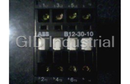
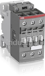
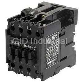
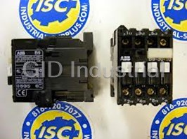
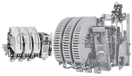
ABB Bar Contactors | Bar Mounted Contactors
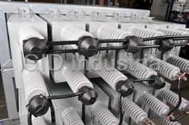
Request a Quote

The quote request has been received
Close

Facing challenges or have inquiries? Feel free to contact us!
Call Us +1-469-283-2440
What they say about us
FANTASTIC RESOURCE
One of our top priorities is maintaining our business with precision, and we are constantly looking for affiliates that can help us achieve our goal. With the aid of GID Industrial, our obsolete product management has never been more efficient. They have been a great resource to our company, and have quickly become a go-to supplier on our list!
Bucher Emhart Glass
EXCELLENT SERVICE
With our strict fundamentals and high expectations, we were surprised when we came across GID Industrial and their competitive pricing. When we approached them with our issue, they were incredibly confident in being able to provide us with a seamless solution at the best price for us. GID Industrial quickly understood our needs and provided us with excellent service, as well as fully tested product to ensure what we received would be the right fit for our company.
Fuji
HARD TO FIND A BETTER PROVIDER
Our company provides services to aid in the manufacture of technological products, such as semiconductors and flat panel displays, and often searching for distributors of obsolete product we require can waste time and money. Finding GID Industrial proved to be a great asset to our company, with cost effective solutions and superior knowledge on all of their materials, it’d be hard to find a better provider of obsolete or hard to find products.
Applied Materials
CONSISTENTLY DELIVERS QUALITY SOLUTIONS
Over the years, the equipment used in our company becomes discontinued, but they’re still of great use to us and our customers. Once these products are no longer available through the manufacturer, finding a reliable, quick supplier is a necessity, and luckily for us, GID Industrial has provided the most trustworthy, quality solutions to our obsolete component needs.
Nidec Vamco
TERRIFIC RESOURCE
This company has been a terrific help to us (I work for Trican Well Service) in sourcing the Micron Ram Memory we needed for our Siemens computers. Great service! And great pricing! I know when the product is shipping and when it will arrive, all the way through the ordering process.
Trican Well Service
GO TO SOURCE
When I can't find an obsolete part, I first call GID and they'll come up with my parts every time. Great customer service and follow up as well. Scott emails me from time to time to touch base and see if we're having trouble finding something.....which is often with our 25 yr old equipment.
ConAgra Foods